Installation and routing of control cables and pipes to connection boxes

Difficulté
Moyen
Durée
2 heure(s)
Sommaire
- 1 Introduction
- 2 Étape 1 - Unless otherwise stated
- 3 Étape 2 - Spindle energy chain assembly
- 4 Étape 3 - Aluminium Infill only Mount energy chains
- 5 Étape 4 - Clearance checks
- 6 Étape 5 - Double plunge control routing
- 7 Étape 6 - Single plunge cable routing
- 8 Étape 7 - Aluminum infill only Mount pre assembled connection boxes
- 9 Étape 8 - Aluminum infill only Clearance checks
- 10 Commentaires
Introduction
Tools Required
Standard screw driver set
Flush side cutters
Parts Required
A0000344 Energy chain bracket set x 8
Étape 1 - Unless otherwise stated
Use Loctite 243 on all fasteners
Pen mark bolts once finalised

Étape 2 - Spindle energy chain assembly
Assembly 8 off spindle energy chains with
27 links for Aluminium infill plate variant
OR
21 links for no infill plate variant
of A0000343 and 1 pair of A0000344
Assemble as image


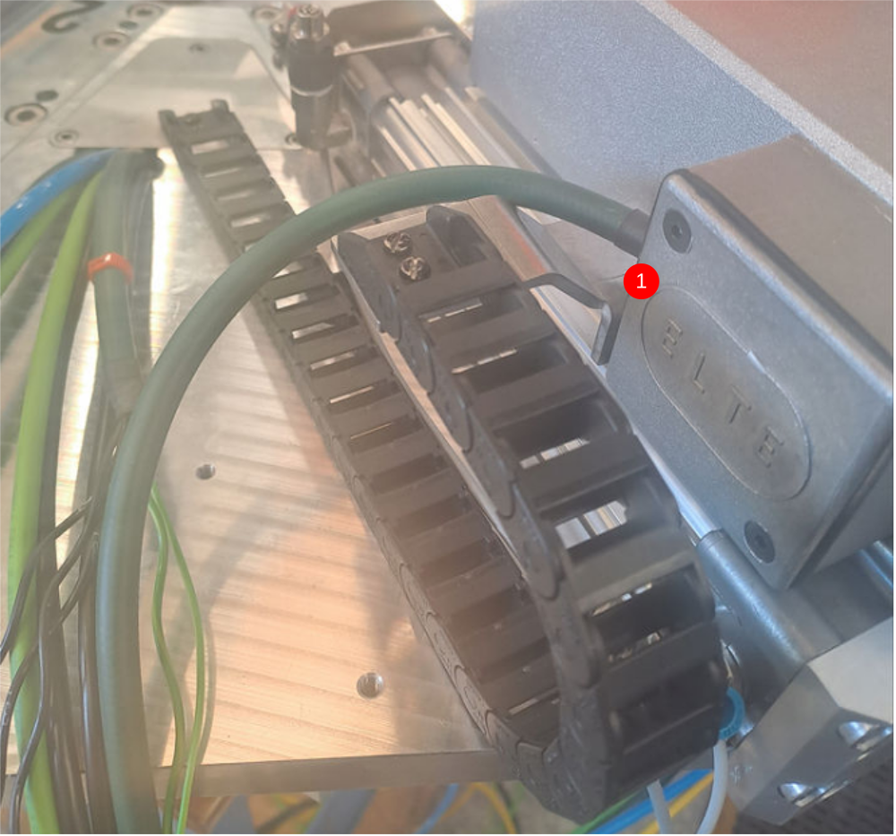
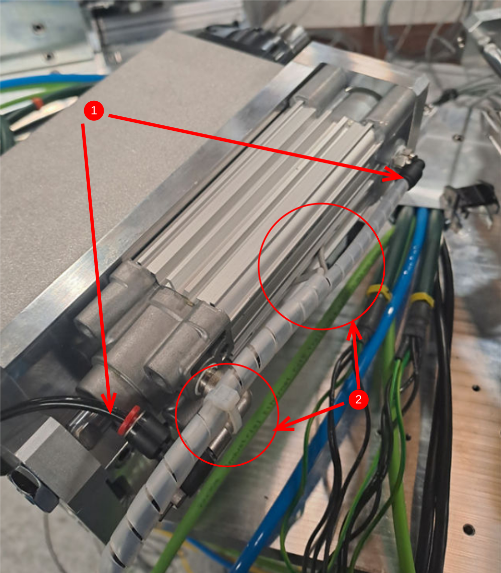
Étape 3 - Aluminium Infill only Mount energy chains
1 Use 4 off m3 x 6 pan head screws and mount energy chains as shown. Ensure energy chain is mounted parallel to the cylinder
2 Disconnect end shown ready for cabling
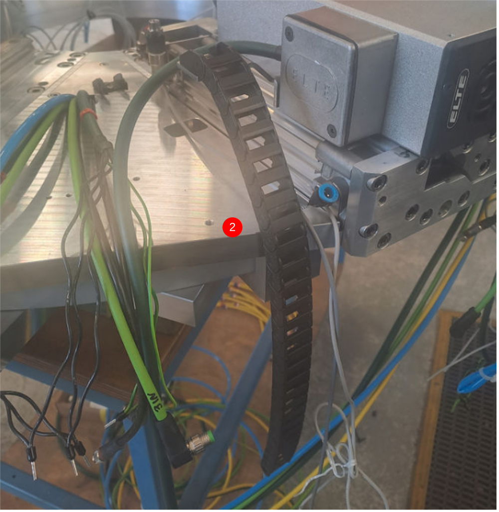
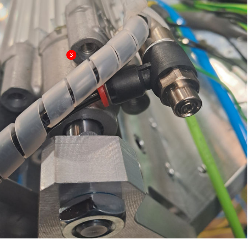
Étape 4 - Clearance checks
It is vital to check that energy chain and mounting bracket clear air fittings when assembly is moved.
Bracket may require adjusting to clear if interference is experienced .
Ensure all spindles are checked


Étape 5 - Double plunge control routing
1 cut 8 off lengths of 4mm black air pipe at 1250mm . Fit to all double plunge cylinder fitting
2 Use small cable wrap at 840mm long to start loom at cylinder end. Incorporate reed switches as passing. Add tie wrap to secure loom
3 Continue loom and fix to tie bases as passing
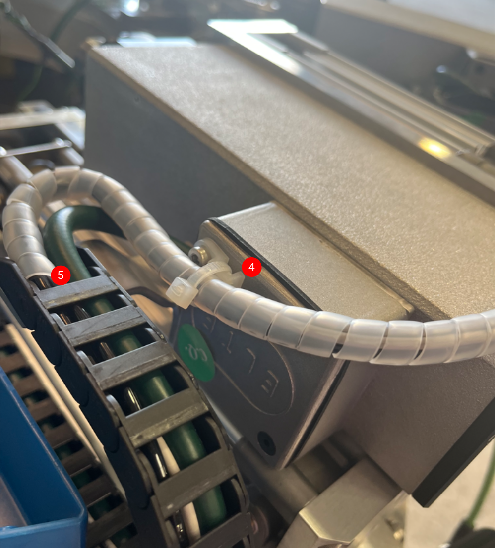
4 Continue loom over terminal box and secure on Tie base
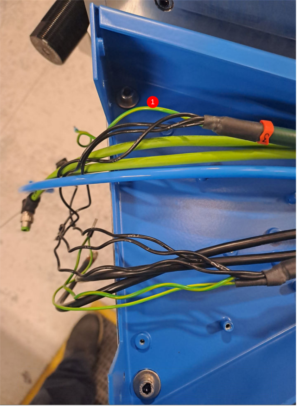
5 Place looms as shown through energy chains
Only reconnect energy chains if aluminum infills are fitted , leave flying if no infill is fitted
6 Reconnect energy chain and leave flying tails in centre of the ring
Repeat for 3 other double spindles
Étape 6 - Single plunge cable routing
Feed motor cable through energy chain and reconnect as shown

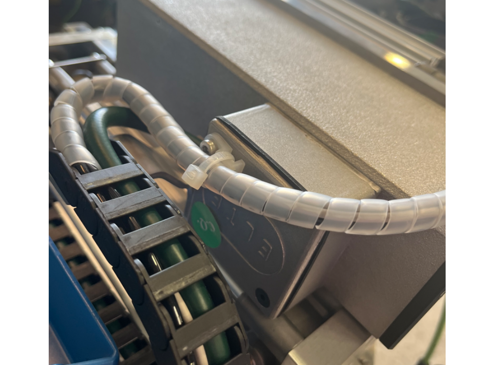
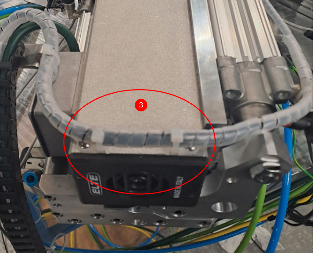
Étape 7 - Aluminum infill only Mount pre assembled connection boxes
1 Mount connection boxes using M5 x 10 button head at cable end and 2 off M5 x 12 cap heads with washers at other end
2 Cables should be separated as shown
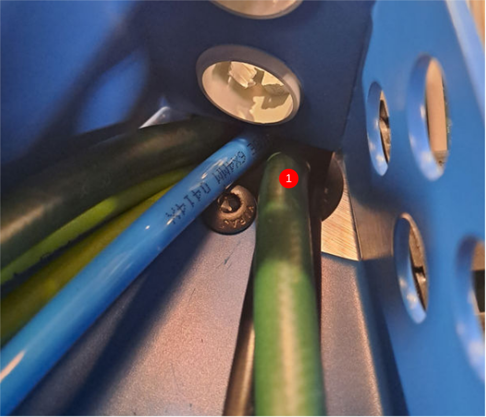
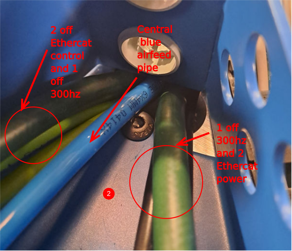
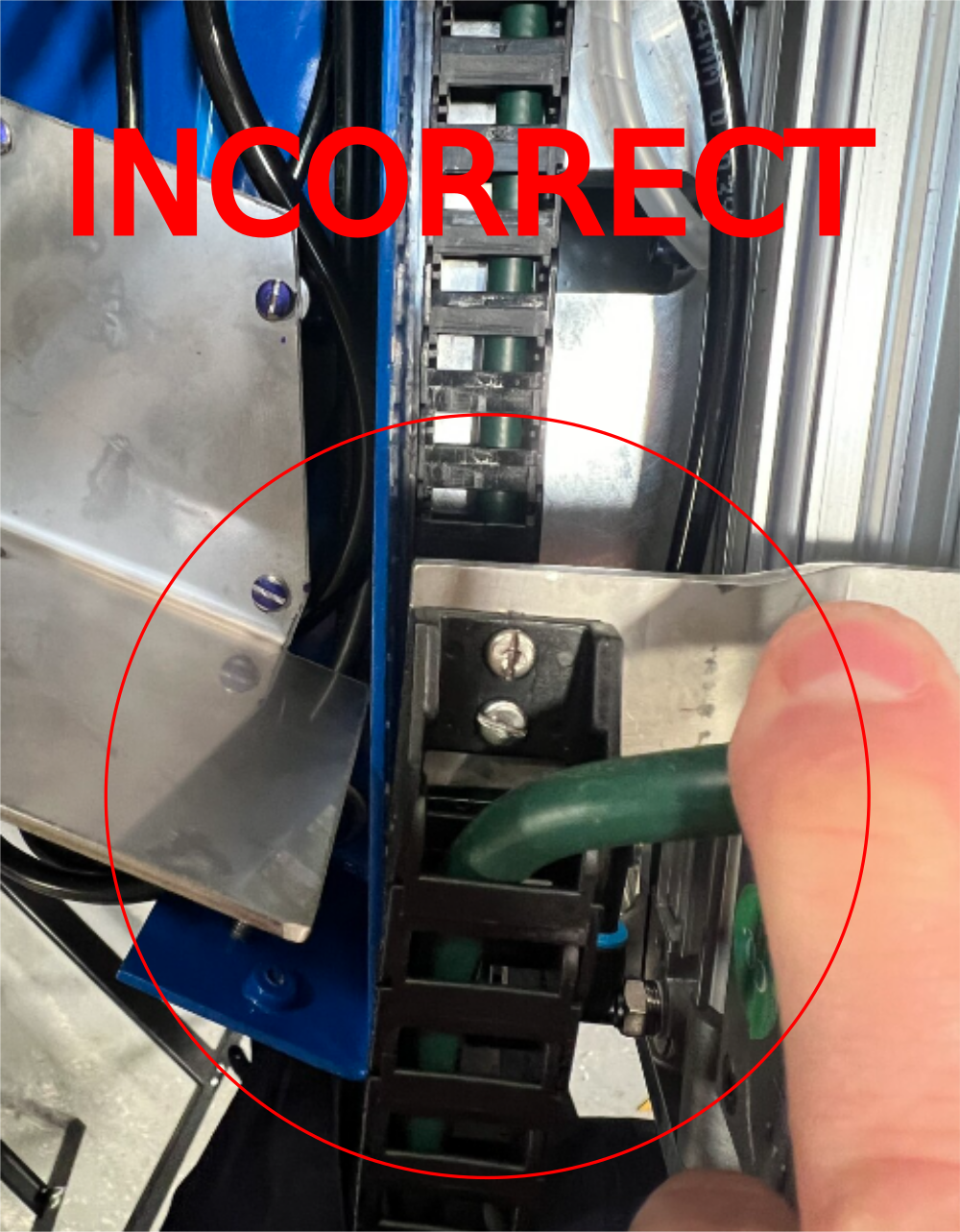
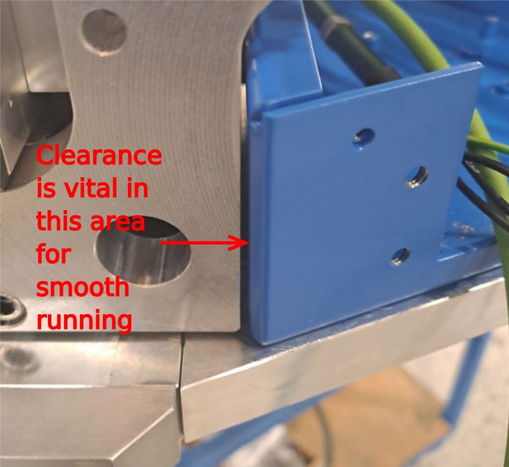
Étape 8 - Aluminum infill only Clearance checks
It is vital to check clearance in the following area. There must be no contact in this area when the spindle is plunged forward.
If contact is occurring, the connection box will need adjusting to gain clearance
To Adjust
1 Remove spindle connection box
2 Elongate mounting holes to give movement int he direction required
3 Refit and adjust to achieve clearance
Draft
 Français
 English
 Deutsch
 Español
 Italiano
 Português