Instructions to install pneumatic connections to main frame

Difficulté
Moyen
Durée
8 heure(s)
Sommaire
- 1 Introduction
- 2 Étape 1 - Unless otherwise stated
- 3 Étape 2 - mount pneumatic rail
- 4 Étape 3 - Valve Bank Connections
- 5 Étape 4 - Y239 Material blower
- 6 Étape 5 - Y231, Y230 and Y299 Pop up feeds
- 7 Étape 6 - Y221 channel
- 8 Étape 7 - Y220 channel lock
- 9 Étape 8 - Y147 pop up E
- 10 Étape 9 - Y146 Roller Bed
- 11 Étape 10 - Important
- 12 Étape 11 - Y131 Grip Height
- 13 Étape 12 - Y241 Rack blower
- 14 Étape 13 - Cable looms
- 15 Étape 14 - Connect ring main
- 16 Commentaires
Introduction
Tools require
Pipe cutters
Number identification
Flush cutters
Parts required
P0000010 Elbow Adaptor 6mm - 1/8 BSPT (Taper thread) x 8
P0000160 Fitting: Flow Controller In Line 6mm x 2
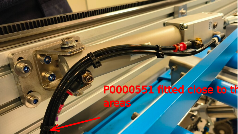
P0000551 6mm inline Quick Exhaust Fitting x 7
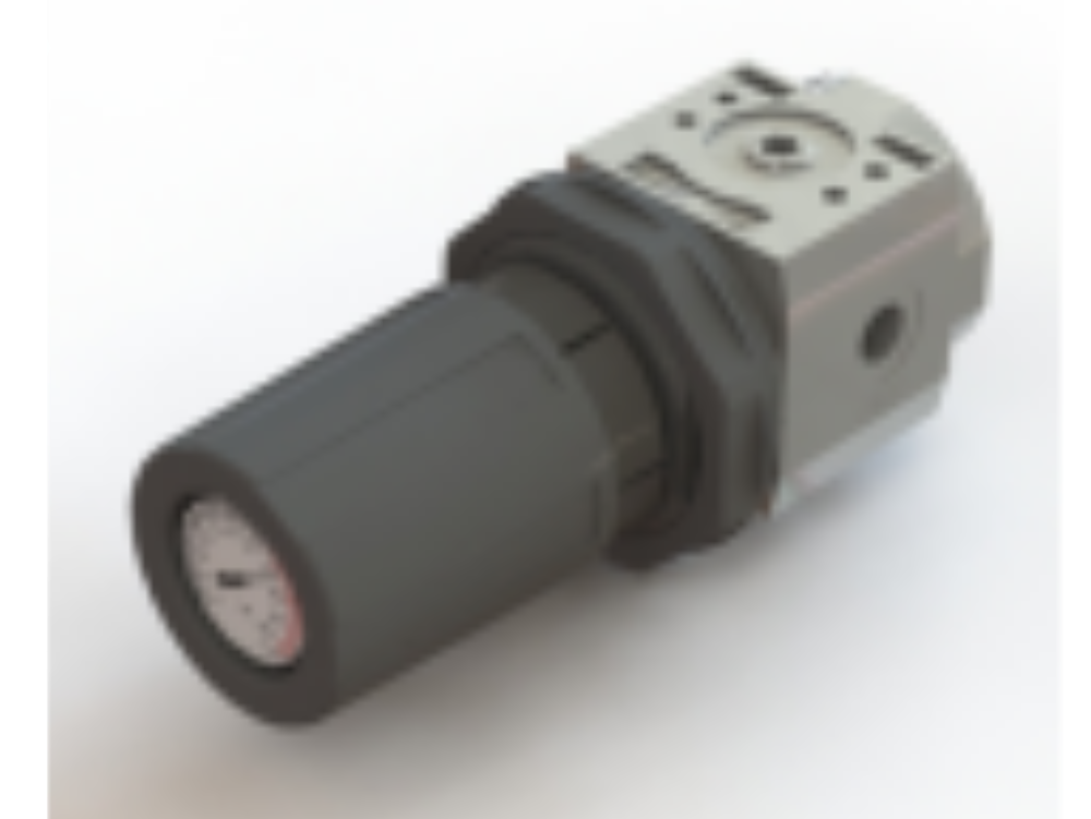
P0001008 Regulator: ARG20 0 - 8.5 Bar c/w Gauge x1
P0001022 Regulator Bracket: to suit P0001008 x 1
A0000343 energy chain x 1
A0000344 energy chain bracket set x 1
D0015577 Fixed energy chain bracket x 1
P0001030 6mm compact tee x 12
Étape 1 - Unless otherwise stated
All bolts to have Loctite 243 adhesive applied unless otherwise stated
All Threaded Pneumatic connections to have Loctite 570 applied
All bolts to be pen marked once adhesive applied and correct tension added

Étape 2 - mount pneumatic rail
Mount pre assembled pneumatic rail with 2 off M8 x 20 socket cps. Use 1 off M8 A Form washer on slotted end of rail
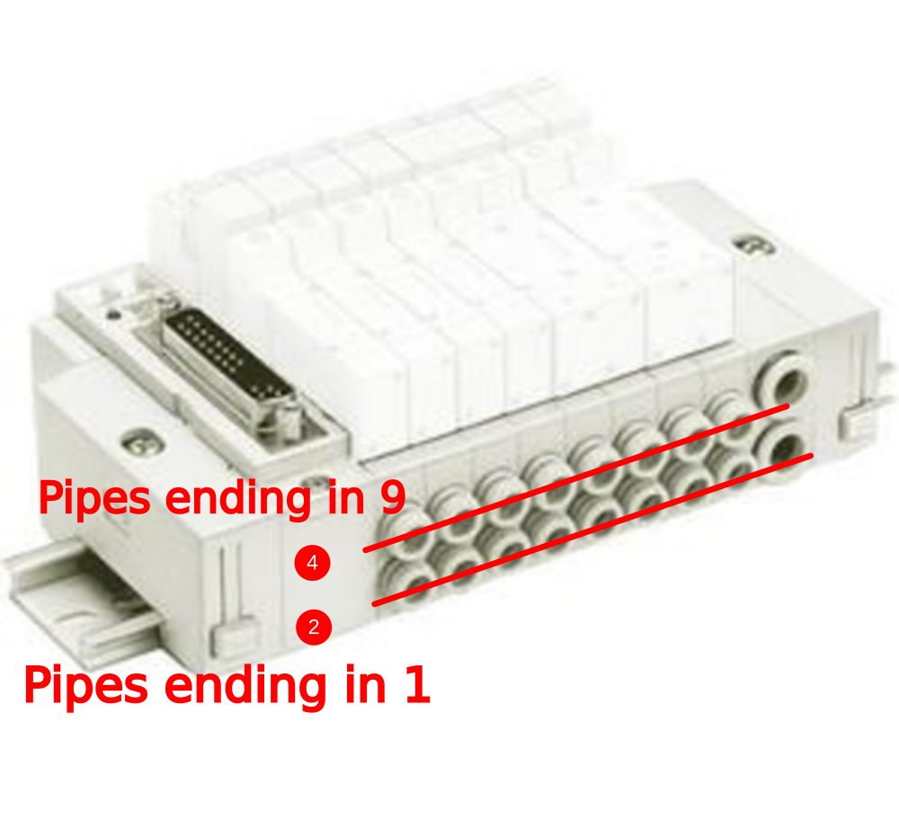
Étape 3 - Valve Bank Connections
Valve bank connections are as follows
Front row of valve bank (4) is the active ports, These will all be connected with suffix 9 pipe identifications
Back row (2) is the home position , these will always be connected with suffix 1 pipe identifications
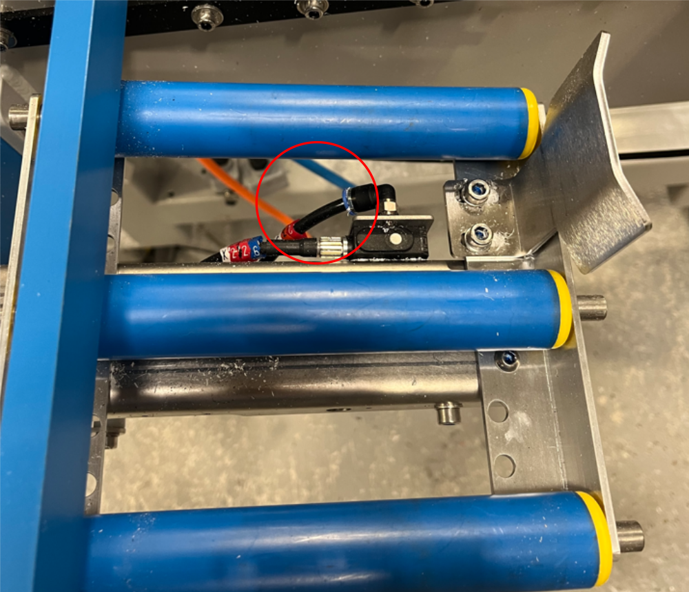
Étape 4 - Y239 Material blower
Material blower should be identified as 2399
Located on roller assembly close to saw unit
P0000160 flow reg required to control flow onto sensors, this should be pre fitted to roller assembly at bench assembly stage
Connect to active port ln valve bank (4)
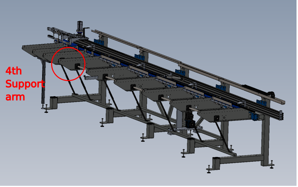
Étape 5 - Y231, Y230 and Y299 Pop up feeds
Feed pipes from valve bank should be run to transfer arm location 4
Identifications will be
2319
2309
2299
Connect to active port on valve bank (4)
Fit A000343 energy chain @40 links
A0000344 energy chain brackets as shown
Mount to D0015577 fixed bracket with M3 x 6 panhead screws and attach to support arm as shown using M4 x 16 socket caps, A form washers and M4 nyloc nuts .
Must have a P0000551 Q.E.V fitted to each line
Ensure 1.5 m of pipe is left exiting the end of the energy chain


Étape 6 - Y221 channel
Use schematic for pneumatic connections
Ensure P0000551 Q.E.V are fitted

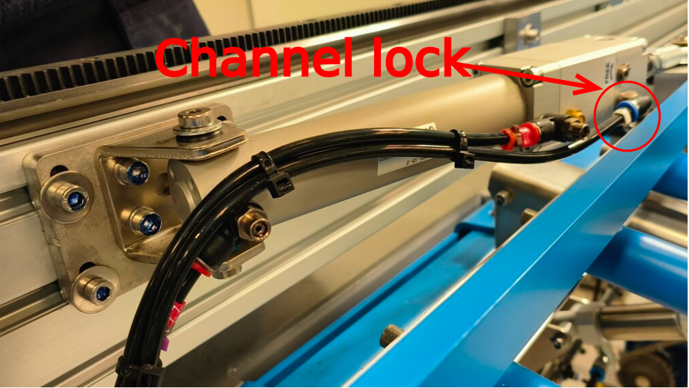
Étape 7 - Y220 channel lock
Identification 2209
Connected to active port of valve bank (4)
Étape 8 - Y147 pop up E
Identification 1479
Connects to active port on valve bank (4)
Use P0001030 compact tee to connect
Ensure enough loom to allow full range of movement

Étape 9 - Y146 Roller Bed
Identification
1461 and 1469
Roller bed is lifted at home position
Use P0001030 6mm tee for connections
1461 to home port on valve bank (2)
1469 to active port on valve bank (4)
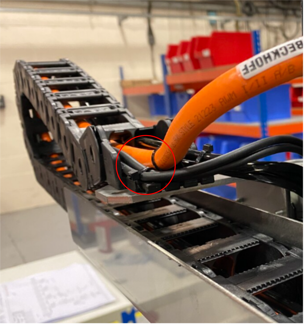
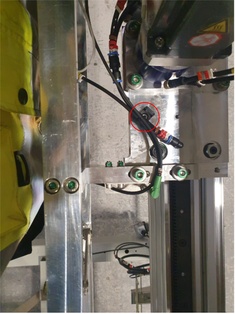
Étape 10 - Important
It is vital that when installing pipes into the main X axis energy chain, that cable retaining points are used
All cables and pipes should be secured with tie wraps to the 'fingers' on the energy chain brackets at BOTH ends

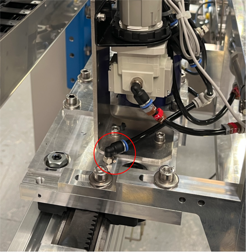
Étape 11 - Y131 Grip Height
Fit tie bases as shown to gripper support arms .
Ecr raised to add holes to drawing 06/11/23
Fit P0001008 Regulator: ARG20 0 - 8.5 Bar c/w Gauge x1
P0001022 Regulator Bracket: to suit P0001008 x 1 to bracket shown
Gripper height is lifted for home position
identification
1311 Home port of valve bank (2) to nose of cylinder
1312 base of cylinder to out port on regulator
Ensure P0000551 Q.E.V are fitted to both grip height cylinder ports
1319 In port of regulator to active port on valve bank (4)


Étape 12 - Y241 Rack blower
Identification 2419
Must have flow regulation P0000160
Split feed with P0001030 6mm tee
Connect to active port (4) on valve bank
Étape 13 - Cable looms
Install 1 off cable tie base as shown
Run cable X44 and X10 as shown
Leave loops of excess cable tied off ready for electrical termination
Leave cable X283 tied off in a loop on cylinder
Étape 14 - Connect ring main
Connect 12mm blue airpipe from valve banks to end of frame for machine connections
Draft
 Français
 English
 Deutsch
 Español
 Italiano
 Português