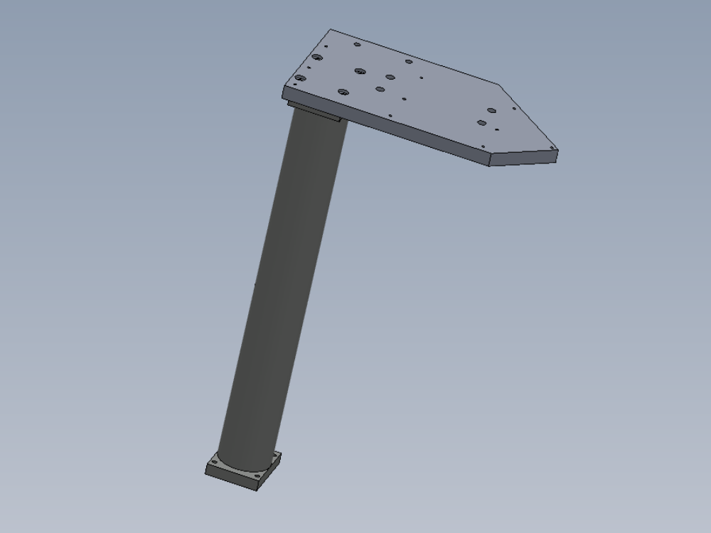
Mounting details for SR axis flag and sensor

Difficulté
Moyen
Durée
0.25 heure(s)
Introduction
Tools Required
Standard Hex key set
Standard spanner set
Parts required
D0015489 Saw Turntable Sensor Bar x 1
E0000336 Sensor: M8; 2mm, PNP N/O, M8 conn x 1
M0001165 U bolt 3nb M12 BZP x 1
Étape 1 - Unless otherwise stated
All bolts to have Loctite 243 adhesive applied unless otherwise stated
All Threaded Pneumatic connections to have Loctite 570 applied
All bolts to be pen marked once adhesive applied and correct tension added

Étape 2 - Attach sensor bracket
Attach u bolt and sensor bracket on infeed mounting pillar
Fix with M12 nuts and M12 A form washers
Ensure bracket is mounted square to pillar base, only apply light tension to M12 nuts


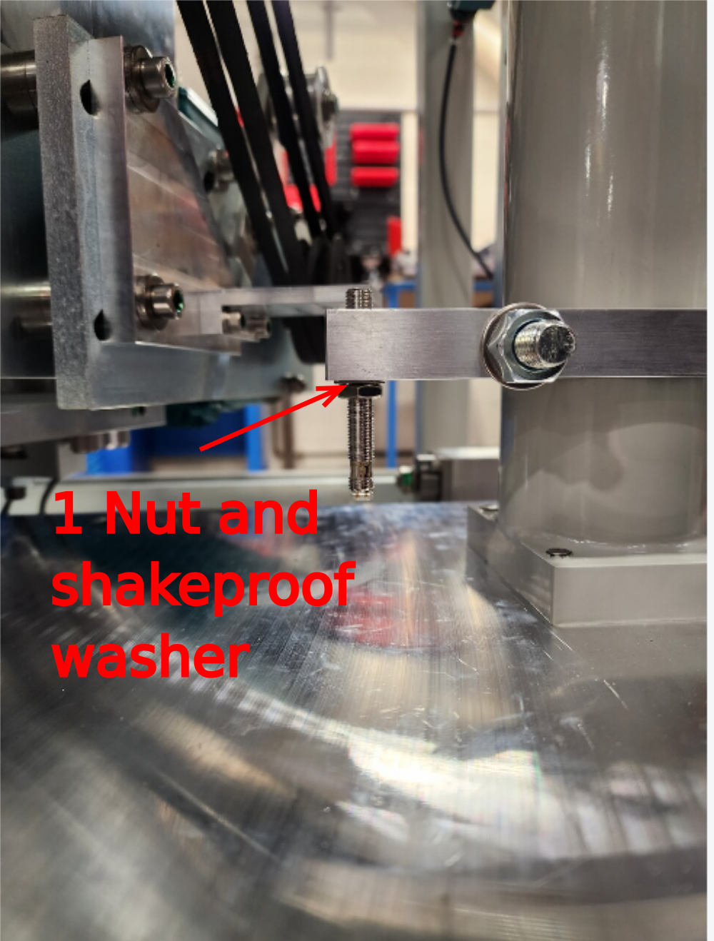
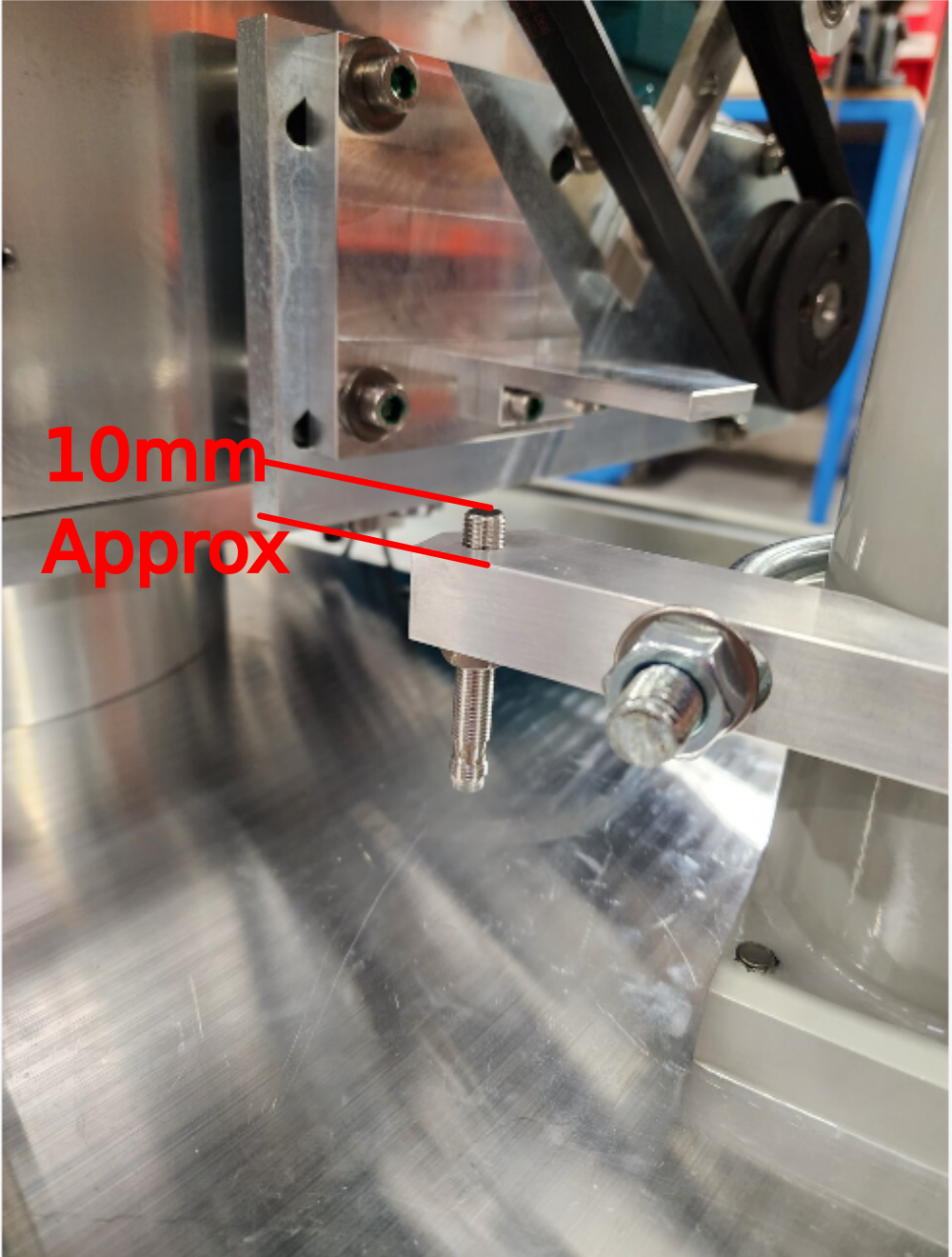
Étape 3 - Fit sensor
Only fit one sensor lock nut and shakeproof washer to assembly as shown
Fit E0000336 sensor to assembly
Leave 10mm protrusion from top of bracket as shown
Ensure shakeproof washer is fitted under sensor nut
Étape 4 - Set height
Set Height of U bolt bracket assembly in relation to flag on saw motor plate, to set sensor withing +- 2mm of flag


Étape 5 - Set sensor height
Set sensor height to minimal clearance (-1mm )
Check gap is consistent on full travel over sensor flag when head is rotated


Étape 6 - Finalise
Finalise M12 nuts and ensure U bolt assembly is mounted true as to not impact on side sheet guarding panel when fitted later
Check sensor position has not moved

Étape 7 - Check sensor
once finalised, double check correct operation of sensor.
Sensor should be within -1mm at all points of travel onto SR axis datum flag. Sensor should NEVER be in contact with flag at any point of movement

Draft
 Français
 English
 Deutsch
 Español
 Italiano
 Português