Instructions to bench assemble roller tables

Difficulté
Moyen
Durée
6 heure(s)
Sommaire
- 1 Introduction
- 2 Étape 1 - Unless otherwise stated
- 3 Étape 2 - Quality Check for Rework
- 4 Étape 3 - Assemble Cylinder assembly
- 5 Étape 4 - Check for rework 13 off
- 6 Étape 5 - Check for rework of following parts
- 7 Étape 6 - Dokit change
- 8 Étape 7 - Fit bushes and mount cylinder
- 9 Étape 8 - Combine support arm and roller bracket
- 10 Étape 9 - Prepare M3 holes
- 11 Étape 10 - Caution
- 12 Étape 11 - Assemble Large roller Table
- 13 Étape 12 - Fit rollers
- 14 Étape 13 - Back fence quality
- 15 Étape 14 - Attach back fence
- 16 Étape 15 - Assemble medium roller table
- 17 Étape 16 - Attach back fence
- 18 Étape 17 - Assemble small roller table
- 19 Étape 18 - Attach back fence
- 20 Étape 19 - Pneumatic pre assembly
- 21 Commentaires
Introduction
Tools Required
Standard Hex key set
Standard spanner set
Tape measure/Rule
8.2mm HSS drill
Drill
Parts Required
B0001092 Plastic roller x 48
B0001103 Bush flange x 28
B0001220 Spacer x 28
D0015001 Roller Bed Cylinder Arm x14
D0015002 Shaft 10mm: 58mm Rod End x 14
D0015003 Roller Bed Rail 375mm x 6
D0015004 Roller Bed Rail 550mm x 2
D0015005 Roller Bed Rail 1000mm x 10
D0015006B Roller Bed Arm Bracket x 14
D0015010 Rod End Spacer x 28
D0015283 Saw Infeed Backfence Plate x 5
D0015481 Shaft 8mm: 50mm Cylinder Pivot x 14
D0015547 Sensor Blower Plate x 1
D0015603 Roller Bed Pivot Shaft (silver steel) x 14
D0015608 Saw Infeed Backfence Plate (Full Length) x 5
E0001120 Sensor: Ultrasonic M8 20-150mm x 1
P0000049 Cylinder Spherical Bearing M10 x 1.25 x 14
P0000200 Elbow Adaptor 6mm - M5 x 1
P0001152 Cylinder 25 x 25 x 14
P0001198 Fitting Speed controller 1/8 x 6mm tube x 28
P0000160 flow regulator x1
Étape 1 - Unless otherwise stated
Use locktite 243 on all fasteners
Use loctite 572 on all threaded pneumatic connection
Pen mark all fasteners to show finalised

Étape 2 - Quality Check for Rework
Back fences D0015608 and D0015283 should be checked for correct issue.
Overall height has been changed from 84mm to 81mm .
Please check all components are made to his new measurement. If old stock is issued, please rework to new dimensions


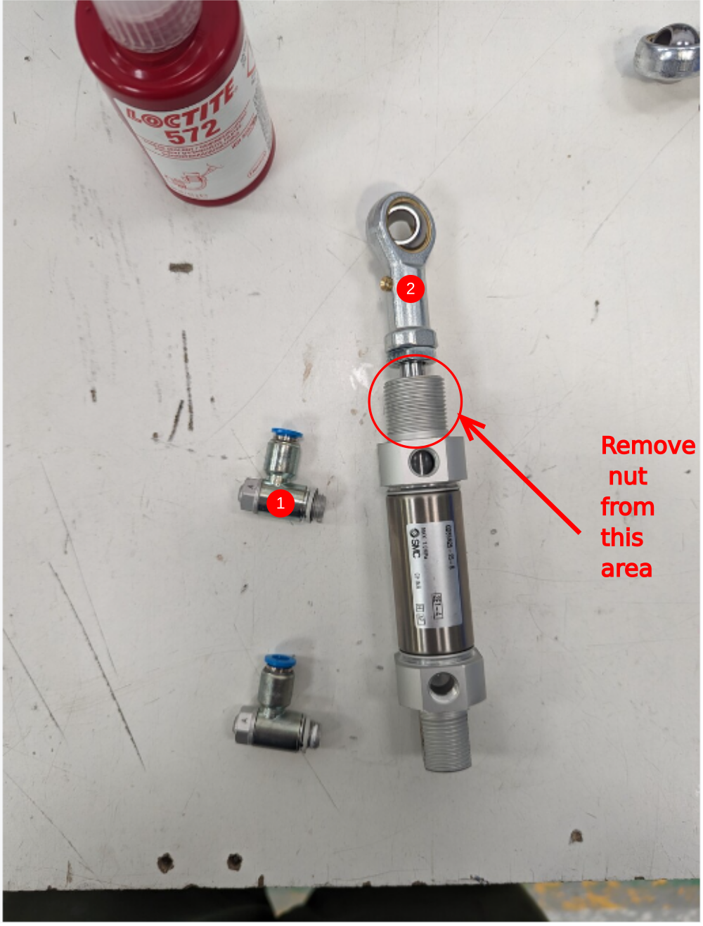
Étape 3 - Assemble Cylinder assembly
2 Fit spherical bearing P0000049 to cylinder end , Do not add final tension to the nut

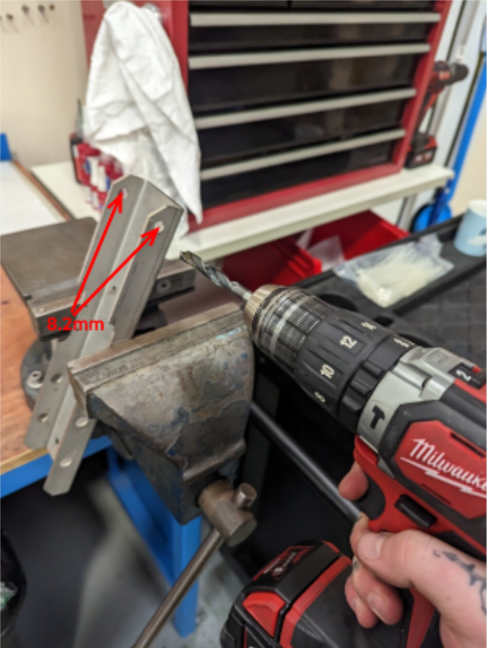
Étape 4 - Check for rework 13 off
14 off
Check part D00150001 has been supplied to new specification
Check indicated hole, should measure 8.2mm. If not open up with hand drill
Drawing change requested 06/06/23 to amend from 8mm to 8.2mm
Étape 5 - Check for rework of following parts
1 D0015006B indicated holes should measure as shown. Rework by hand if issued old spec
ECR raised 06/06/23
2 D0015002 rod end shaft . Check fit in P0000049 spherical bearing . Polish down diameter to allow shaft to pass through.
ECR raised 06/06.23 to improve tolerance of shaft to allow better fitment


Étape 6 - Dokit change
Please be aware following step has been amended to include new assembly details.
It is now required to assemble 3 off of the 14 off cylinder mounts differently
Amendment to fastener type used

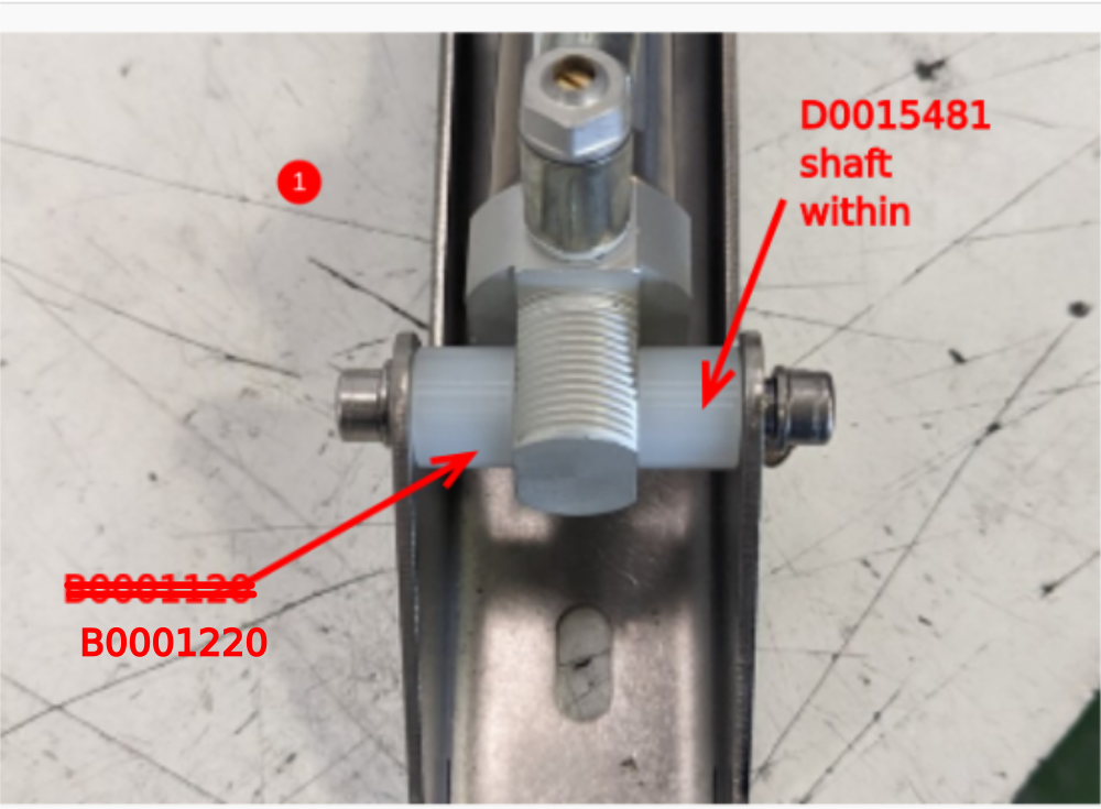
Étape 7 - Fit bushes and mount cylinder
14 off
1 Combine D0015481 shaft and B0001220 spacer as shown to mount cylinder to bracket. Use M6 x 12 socket caps and A form washers to fasten on 11 off cylinder mounts. Use M6 x 12 hex set bolts with no washers on 3 off cylinder mounts
2 Fit 2 off B0001103 bushes to D0015006B


Étape 8 - Combine support arm and roller bracket
14 off
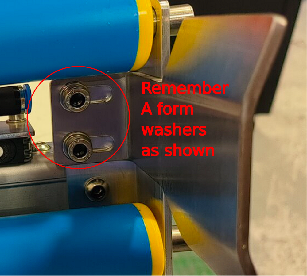
1 Fit 2 off D0015010 spacers, 1 off d0015002 shaft through spherical bearing and fix with 2 off m6 X 12 socket caps and A form washers
2 Fit 1 0ff D0015603 pivot shaft with 2 off M6 x 12 socket caps and A Form washers

Étape 9 - Prepare M3 holes
1 Tap 2 off indicated holes M3
Étape 10 - Caution
Please ensure correct assembled cylinder mounts are fitted to the correct assemblies
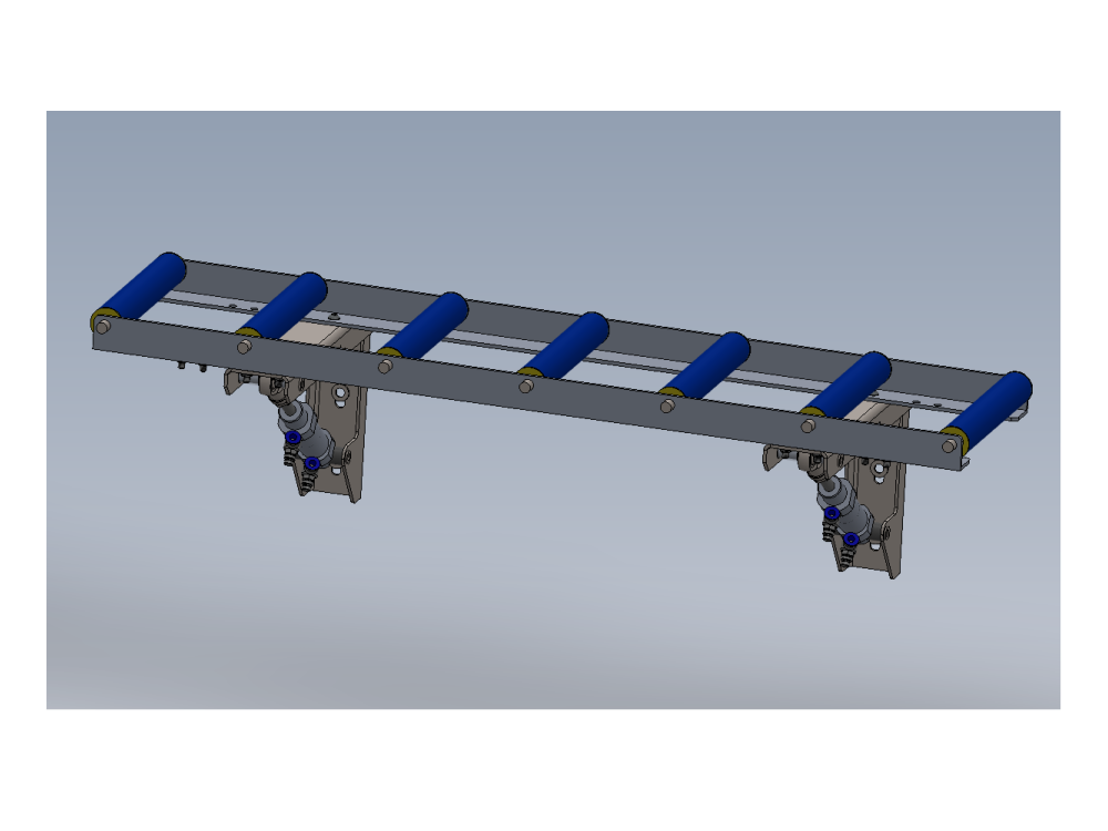
Étape 11 - Assemble Large roller Table
5 off to be assembled
Use cylinder bracket assemblies with Socket cap heads
1 Mount 2 off D0015005 to prebuild cylinder assemblies as shown
Use M6 x 20 button socket , A form washer and M6 nyloc nuts to fix.
Do not use washer under head of button head screw, on use on on nut side
2 Adjust the 2 off D0015005
1st section pushed against edge of clearance hole in direction shown
2nd section pushed in same direction
3rd Check parallel and adjust to correct
4th check squareness by taking corner measurements and adjusting if required
Once all above is achieved, finalise fasteners


Étape 12 - Fit rollers
Fit 7 off B0001092 roller to each assembly

Étape 13 - Back fence quality
D0015283 Saw Infeed Backfence Plate x 5 and D0015608 Saw Infeed Backfence Plate (Full Length) x 5 should be supplied from manufacturer free from burrs and sharp edges
Please check these parts are correct, if sharp edges are present please report
Étape 14 - Attach back fence
5 off
Attach D0015069 backfence to roller assembly using M6 x 16 socket caps, A form washers and M6 nyloc nut
Étape 15 - Assemble medium roller table
Ensure cylinder assemblies with socket caps fitted are used on these assemblies
Using same checks and setting as above assemble 1 off roller table with 4 rollers as shown

Étape 16 - Attach back fence
1 off
Attach 2 off D0015283 backfence to roller assembly using M6 x 16 socket caps, A form washers and M6 nyloc nut

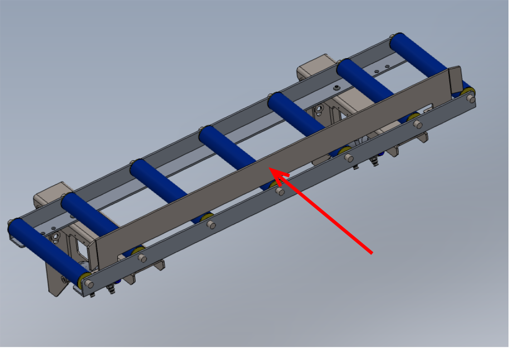
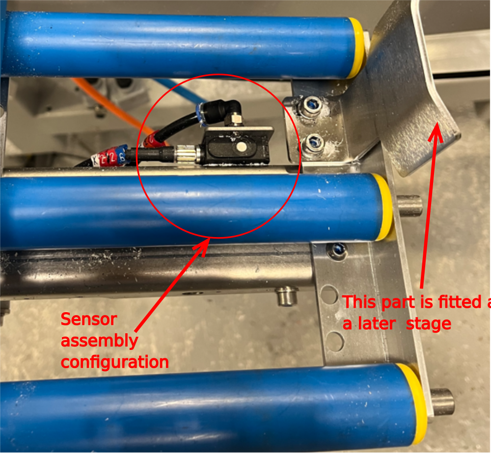
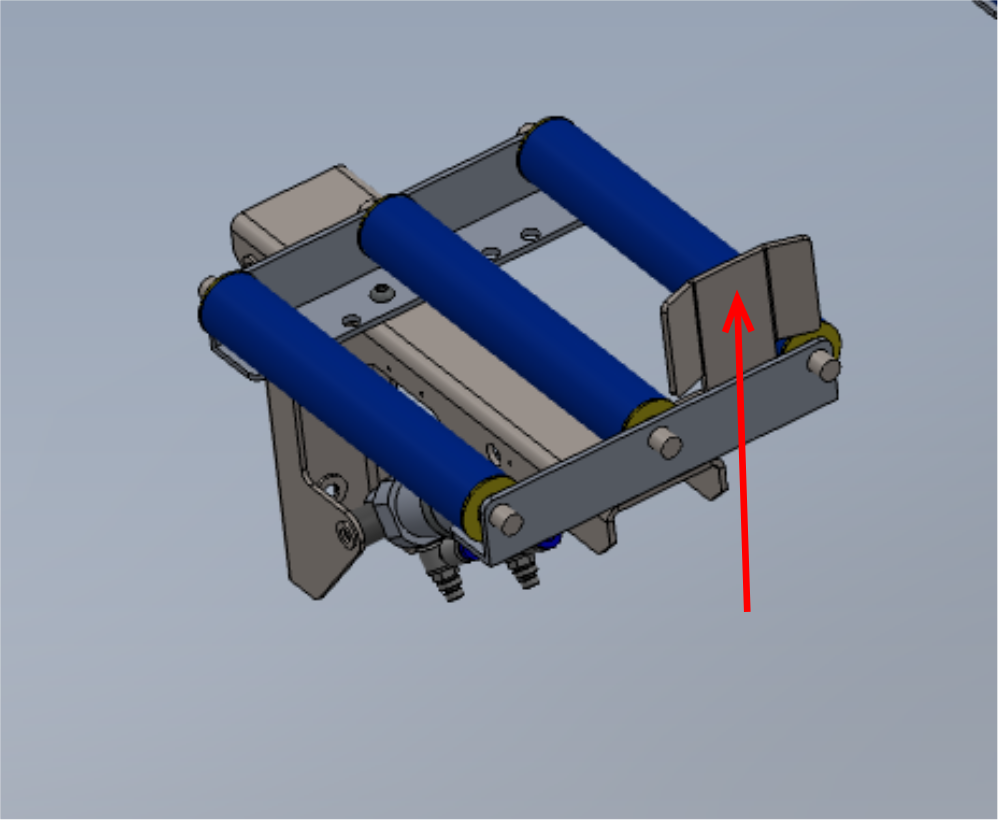
Étape 17 - Assemble small roller table
Cylinder assemblies with HEX SET bolts must be used on these 3 off small roller tables
3 off
Using same checks and setting as above assemble 2 off roller tables with 4 rollers as shown,
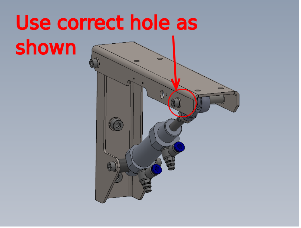
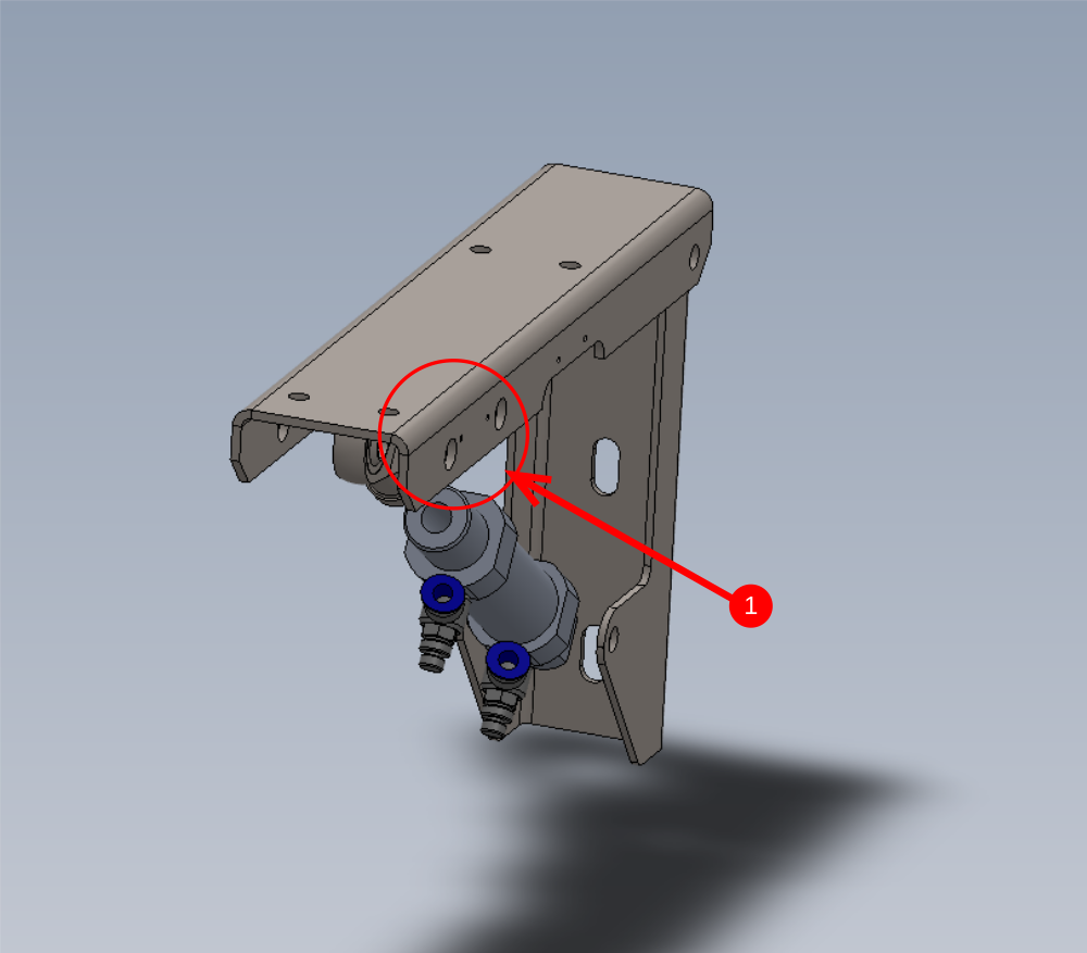
Use the pre built cylinder bracket with m3 tapped holes for 1 off, and add 1 off Sensor E001120 ,1 off Blower P0000200 and 1 off bracket D0015547 as shown. Identify pipe as 2399 and fit P0000160 flow regulator to pipe


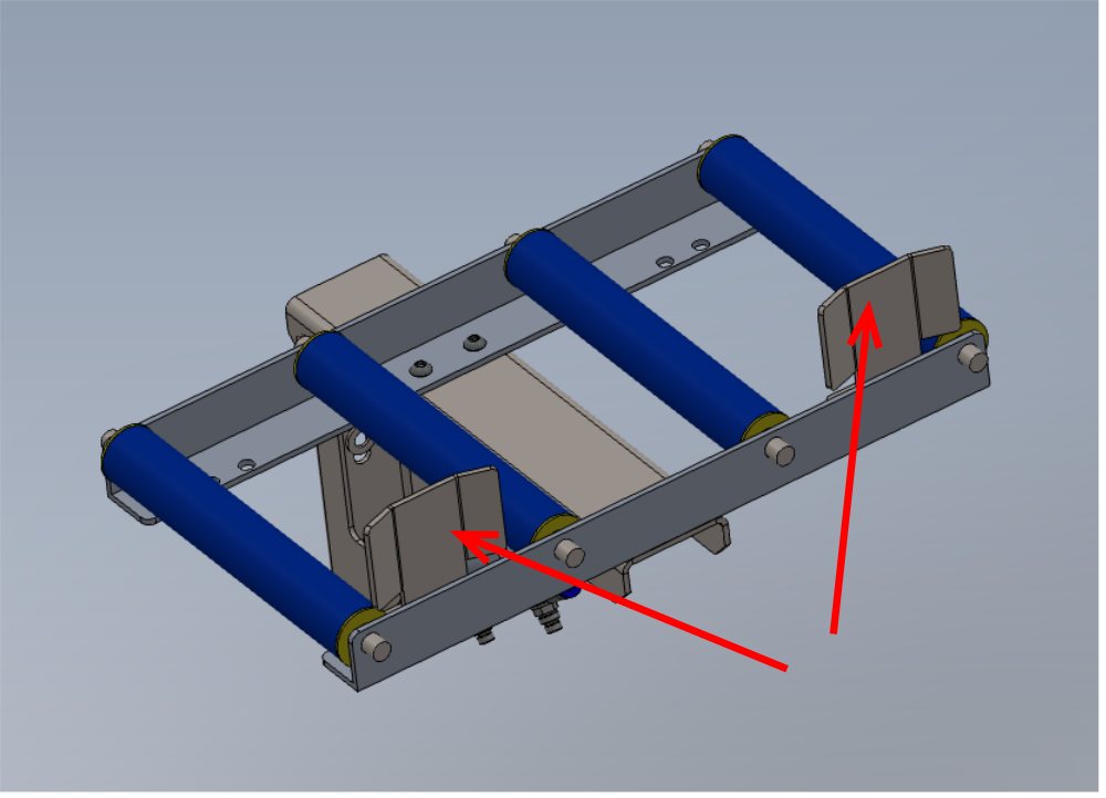
Étape 18 - Attach back fence
3 off
Attach 1 off D0015283 backfence to roller assembly using M6 x 16 socket caps, A form washers and M6 nyloc nut
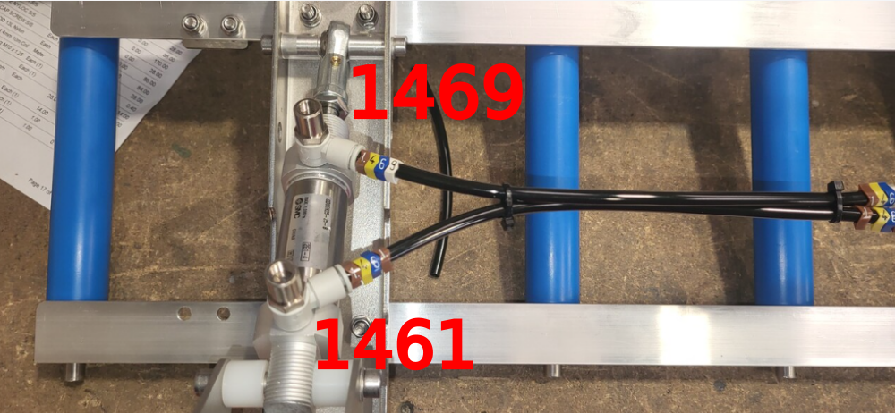
Étape 19 - Pneumatic pre assembly
5 off
7 Roller bed assemblies with two cylinders require pneumatic pipe installation.
Use identification numbers as follows
1461 Home position
1469 Active position (down)

Draft
 Français
 English
 Deutsch
 Español
 Italiano
 Português