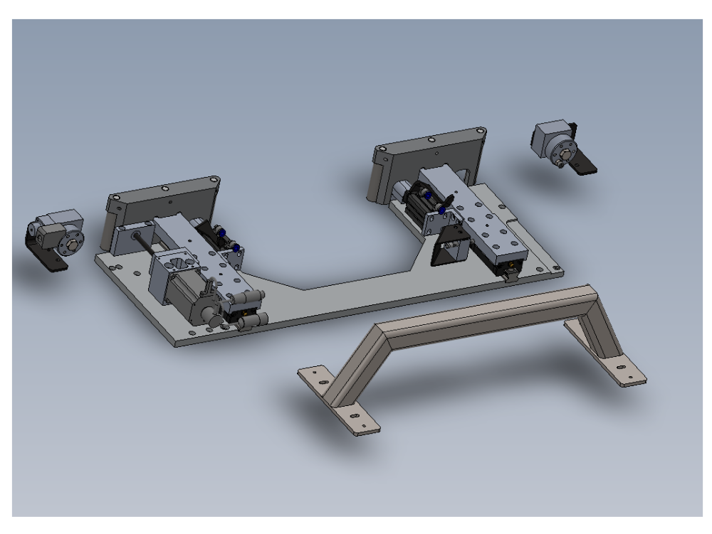
Bench assembly instructions for SY assembly

Difficulté
Difficile
Durée
6 heure(s)
Sommaire
- 1 Introduction
- 2 Étape 1 - Unless otherwise stated
- 3 Étape 2 - Fit bearings to rollers
- 4 Étape 3 - Optional R0019222 roller upgrade
- 5 Étape 4 - Fit guide pin washers and Assemble
- 6 Étape 5 - Shaft orientation
- 7 Étape 6 - Position rollers
- 8 Étape 7 - Optional R0019222 roller upgrade
- 9 Étape 8 - Quality check
- 10 Étape 9 - ECR Raised
- 11 Étape 10 - Pre assembly
- 12 Étape 11 - Quality Check
- 13 Étape 12 - Pre assembly
- 14 Étape 13 - Pre assembly Centralise plate
- 15 Étape 14 - Assemble linear rail assembly
- 16 Étape 15 - Assemble linear rail assembly
- 17 Étape 16 - Align roller fences
- 18 Étape 17 - Align roller fences extra photos
- 19 Étape 18 - Quality check D0015208 servo mounting block
- 20 Étape 19 - Assemble leadscrew components
- 21 Étape 20 - Assemble leadscrew components
- 22 Étape 21 - Mount leadscrew assembly
- 23 Commentaires
Introduction
Tools Required
Standard Hex Key set
Standard Spanner set
1 Meter straight edge
Feeler Gauges
Parts Required
B0000044 Linear Rail MSB25 260mm Long (AMT) x 2
B0000046 Slide Base Bearing Block (Straight Grease Nipple) x 4
B0000173 blanking cap x 10
B0000234 Straight Grease Nipple M6 ST/ST x 4
B0000245 Needle Bearing 12 D 16 D 10 Long (ENA) x 12
B0001060 Grease Fitting M6x0.75 to Ø4 x 4
B0001061 Grease fitting M6 x 1 to 4mm x 4
B0001123 Double angular contact bearing 6 I/D 17 O/D 9 long x 2
B0001185 Leadscrew nut Igus x 1
C0001005 Stepper Motor AS1050 x 1
D0005184 Guide Roller x 6
D0005186 Guide Pin Washer x 6
D0015172 Centralise Plate (with SY) x 1
D0015173 Saw SY Saddle Brace x 1
D0015174 Roller Fence (With SY) x 2
D0015175 Saw Saddle Carriage Block x 2
D0015176 Cylinder Mount Block x 2
D0015178 Z Block x 2
D0015207 Outer Bearing Housing x 1
D0015208 Leadscrew Bearing Block x 1
D0015209 Leadscrew Attachment Bracket x 1
D0015222 SY Grease Manifold x 2
D0015240 Collar Clamp: SY Axis ZX5 x 1
D0015316 Leadscrew Bearing Block Cover x 1
D0015415 Turret Pickup Arm ZX5 x 2
D0015416 Bracket: Turret Stop RH ZX5 x 1
D0015417 Bracket: Turret Stop LH ZX5 x 1
D0015698 Flag Block x 1
D0015777 Leadscrew SY x 1
D0016336 SY table blower x 1
E0000336 Sensor: M8; 2mm, PNP N/O, M8 conn x 1
H0005185 Shaft 12mm: 90.5 Saw Fence Roller Pin x 6
M0001209 Bracket m8 proximity sensor 90 degree x 1
P0000200 Elbow Adaptor 6mm - M5 x 7
P0001127 Guide cylinder 20 x 30 compact x 2
P0001157 Turret Stop: 6 Station Right Handed Somatec x 1
P0001158 Turret Stop: 6 Station Left Handed Somatec x 1
Étape 1 - Unless otherwise stated
All bolts to have Loctite 243 adhesive applied unless otherwise stated
All Threaded Pneumatic connections to have Loctite 570 applied
All bolts to be pen marked once adhesive applied and correct tension added

Étape 2 - Fit bearings to rollers
Assemble 6 off D0005184 Guide Roller
Each roller has 2 off B0000245 Needle Bearing fitted
Ensure bearings are fitted correct orientation . Writing on edge of bearing should be face outwards
Use bearing dolly and push bearing down to should within roller body
Apply liberal grease to all bearings within rollers


Étape 3 - Optional R0019222 roller upgrade
Fit 8 off B0000416 Bearings to 4 off D0010357 backfence rollers. Ensure bearings are pushed to shoulder within rollers
Fit 4 off D00110358 roller pin to assembled rollers, ensuring fitting pin does not change position of fitted bearings


Étape 4 - Fit guide pin washers and Assemble
1 Fit 6 off D0005186 Guide Pin Washer to H0005185 Shaft 12mm: 90.5 Saw Fence Roller Pin
Hold shaft in vice and use M5 x 12 socket cap to secure washer to end of shaft . Finalise bolt
Repeat for all 6 shafts/washers
2 Fit Rollers to shafts


Étape 5 - Shaft orientation
Dimples in H0005185 Shaft are not used in this application.
When fitting shaft , position dimple 180 degrees opposing M6 fixing point in backfence


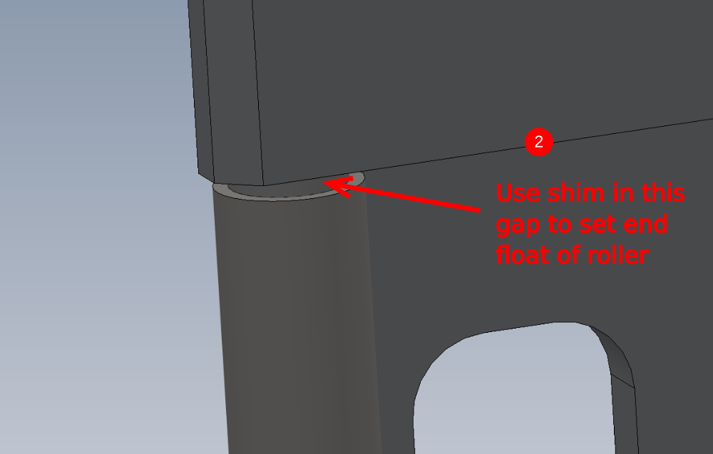
Étape 6 - Position rollers
1 insert shaft into bore following previous step information
2 Insert 0.125mm/0.005" shim between roller and backfence at indicated point
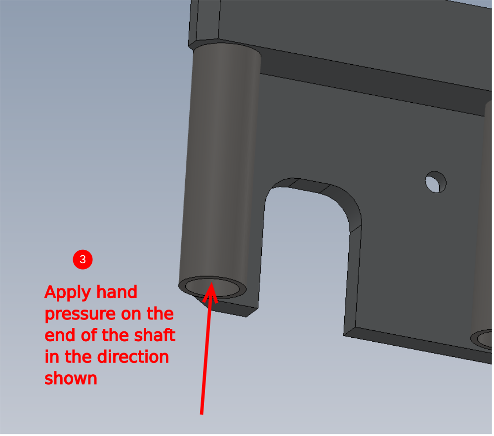
3 Apply very light hand pressure to area shown to position shaft correctly
4 Fit and finalise M6 x 10 kcp grubscrew to secure shaft
5 Remove shim, as only very light hand pressure has been used, this will mean the shim can be extracted without the need to release pressure on the M5 socket cap holding the roller in position
Repeat for all 6 rollers
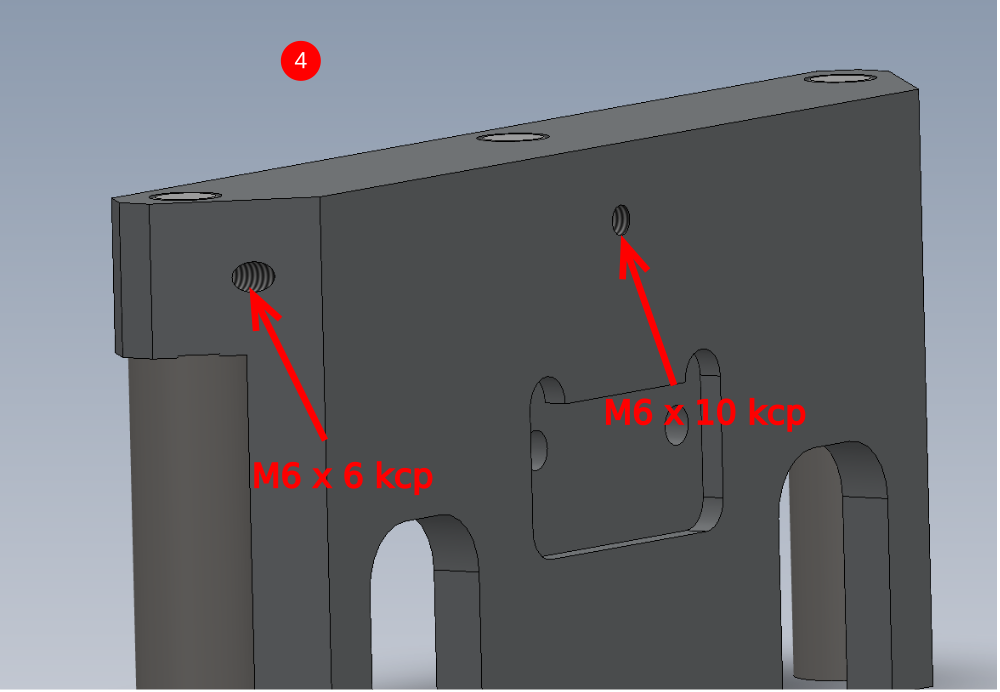

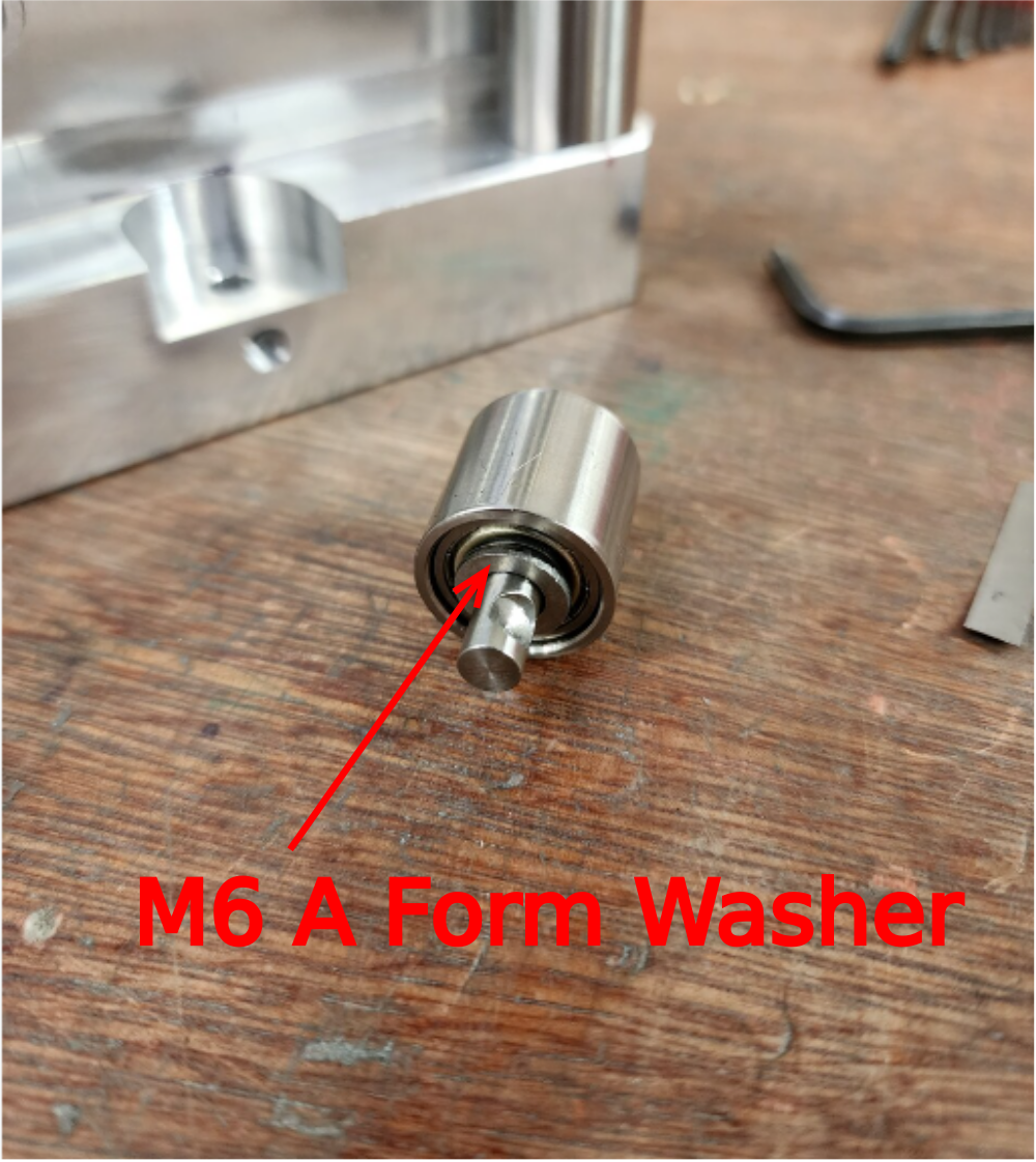
Étape 7 - Optional R0019222 roller upgrade
Assemble optional rollers onto supplied roller housings
Ensure M6 A form washer is fitted to small rollers as shown
Secure shafts with M6 x 6 pointed grubscrews


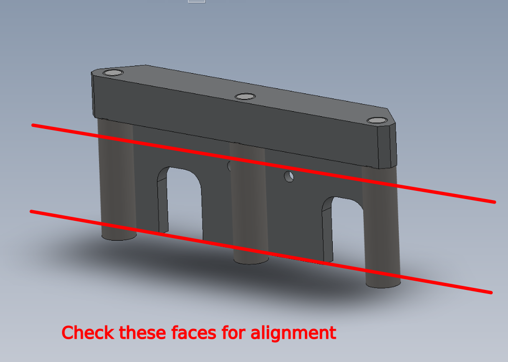
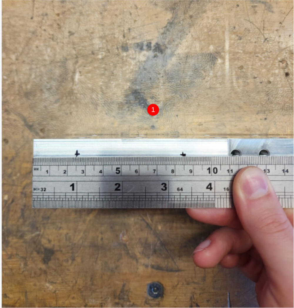
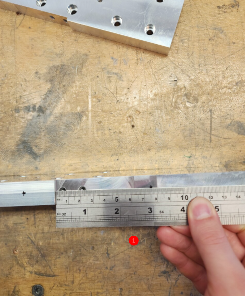
Étape 8 - Quality check
Use 1 meter straight edge to check alignment of rollers
Place straight edge against front face of rollers
Use feeler gauges to check
Mis alignment of rollers on the plain indicated
Rotate rollers individually to check for eccentric rotation.
Report any discrepancies above 0.002"/0.05mm to supervisor


Étape 9 - ECR Raised
ECRs raised to cover all below modifications

Étape 10 - Pre assembly
1 Assemble tie bases onto D0015175 Saw Saddle Carriage Block as shown Drill and tap M4 and fit m4 cable tie bases and secure with M4 x 6 button head as shown
Étape 11 - Quality Check
D0015222 must be checked for correct manufacturing.
Ensure indicated area is checked to ensure bore between 2 greasing points is not open

Étape 12 - Pre assembly
Use D0015222 SY Grease Manifold as jig to drill 2 off M5 tapped holes to secure Add M4 Tapped hole beside to fix a M4 cable tie base
Assemble each SY grease manifold with 2 off M6 straight grease nipples and 2 off B0001061 Grease fitting M6 x 1 to 4mm as shown.
Secure with M5 x 20 socket caps and A form washers


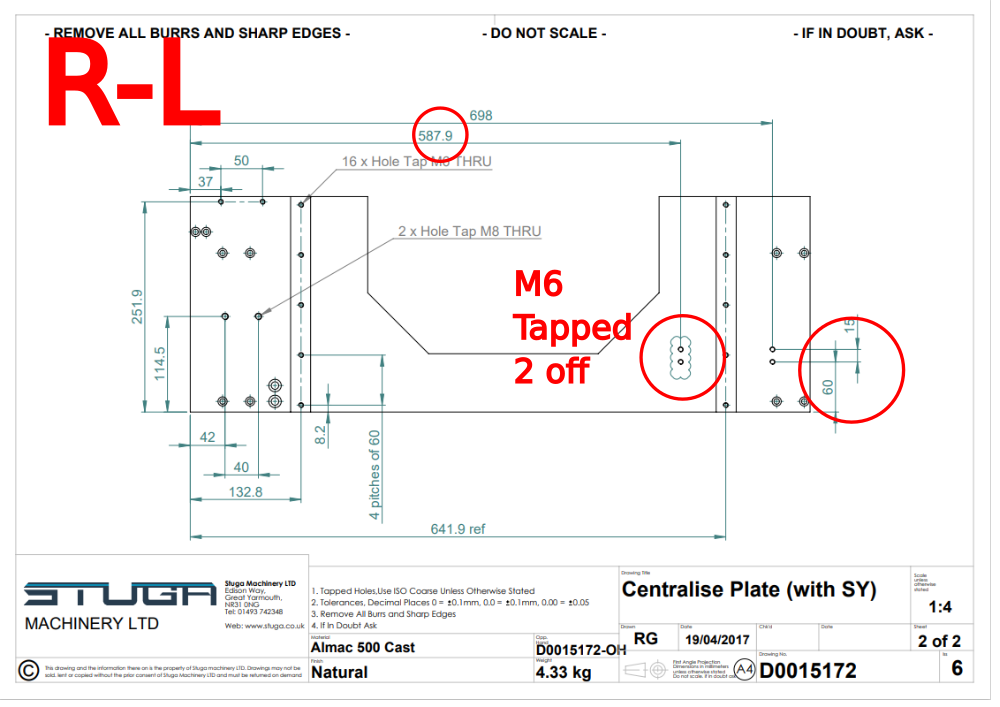
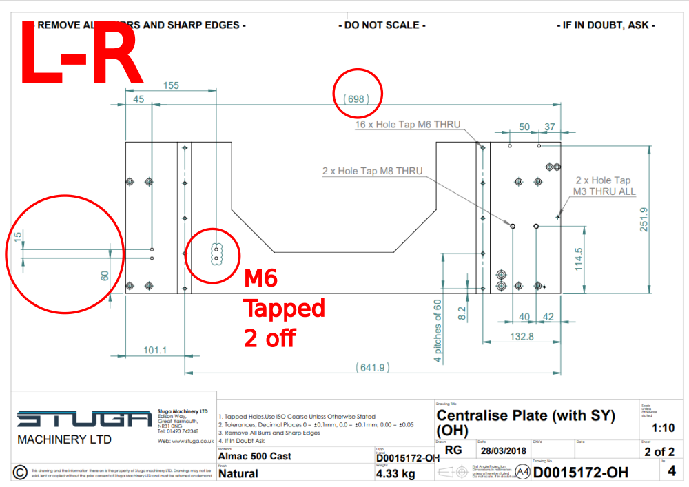
Étape 13 - Pre assembly Centralise plate
D0015172 Check for rework. Add if not present
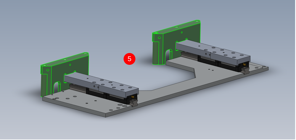
Étape 14 - Assemble linear rail assembly
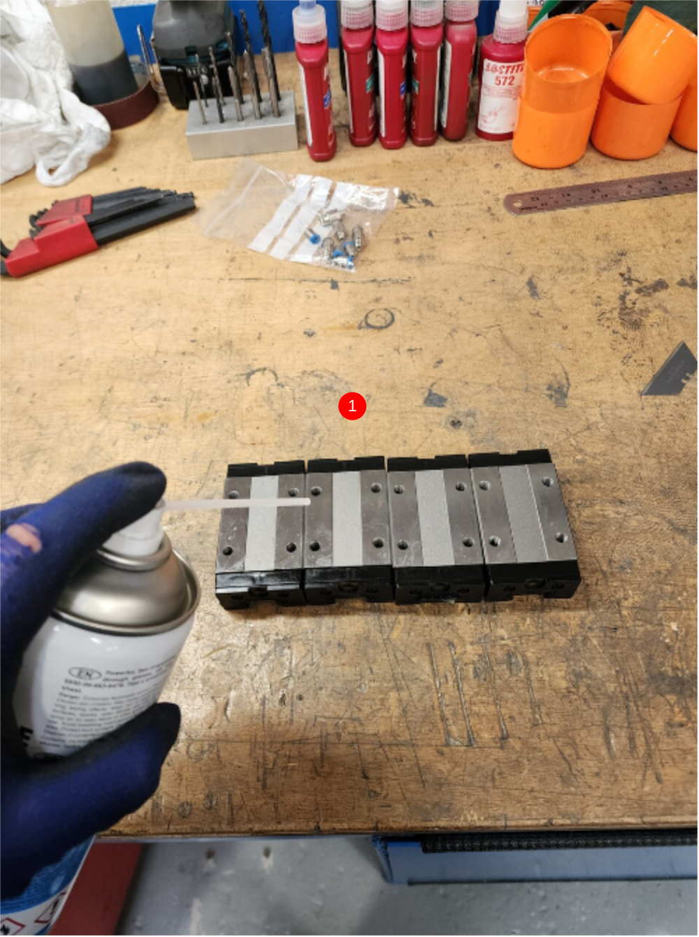
1 Degrease B0000046 Slide Base Bearing Block with Fe10. Fit 4 off B0001060 Grease Fitting M6x0.75
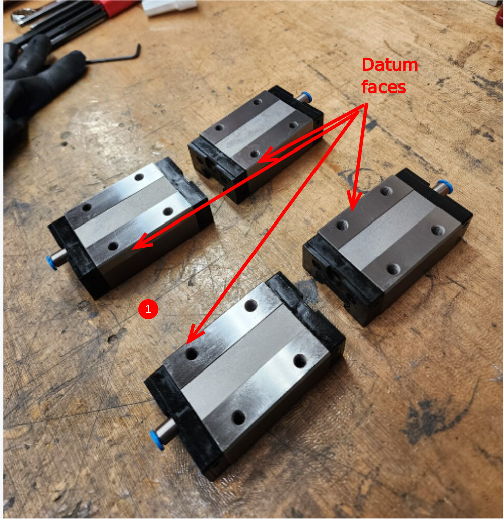
2 Fit 2 off B0000044 Linear Rail to D0015172 Centralise Plate as shown. Use M6 x 16 socket caps , do not apply final tension or adhesive.Ensure datum faces on rails both face inwards as shown
3 Fit 4 off B0000046 Slide Base Bearing Block as shown. Again ensure datum faces are orientated the same way as the linear rails
4 Fit 2 off D0015175 Saw Saddle Carriage Block, Use M6 x 16 socket caps. Ensure requested bolts are omitted as shown
Apply final tension and adhesive to these bolts
5 Fit roller assemblies and fix with M6 x 16 socket caps and A form washers


Étape 15 - Assemble linear rail assembly
Photos for clarity


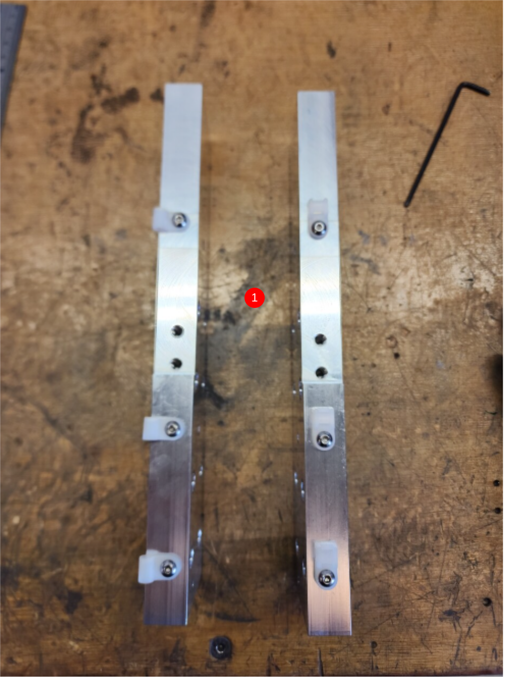
Étape 16 - Align roller fences
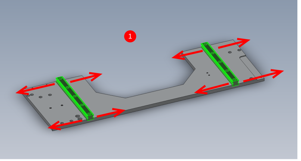
1 Possible Adjustment directions are shown using clearance it the counterbored linear rail holes
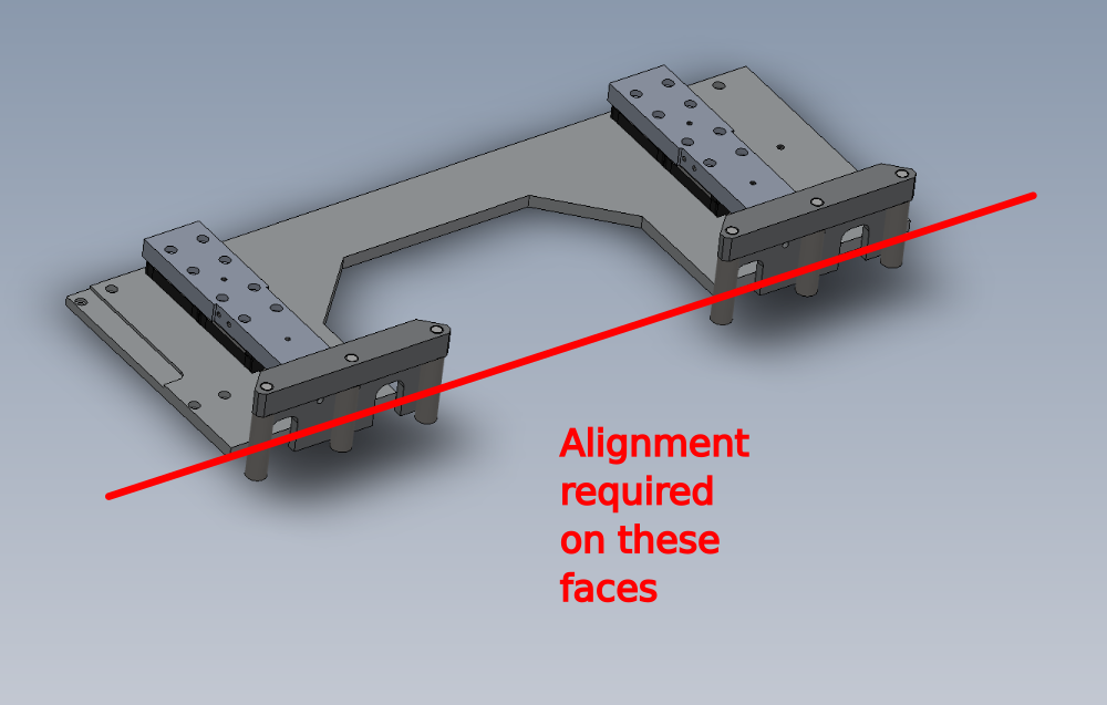
2 Alignment requirement
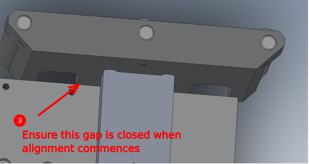
3 Starting position for alignment, ensure roller fence blocks are pushed against centralise plate
4 Adjust linear rails to enable both front fence rollers to be aligned correctly
5 Tolerance of 0.002"/0.05mm to be adhered to. Any discrepancy report to supervisor
6 Finalise M6 x 16 socket caps that hold the position of the B0000044 Linear Rail
7 Add 10 off B0000173 blanking caps to finalise rails. Ensure caps are fitted flush to rail. Bearing rails can be removed to allow access to covers caps to be fitted. Take care when re fitting bearings onto rails


Étape 17 - Align roller fences extra photos


Étape 18 - Quality check D0015208 servo mounting block
Check indicated measurement of 49mm is checked before assembly . Any discrepancy should be reported to supervisor

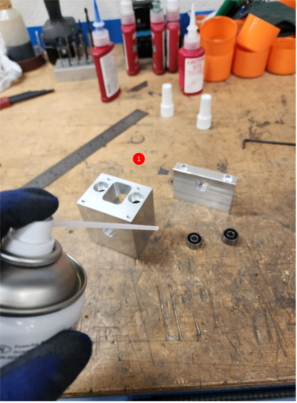
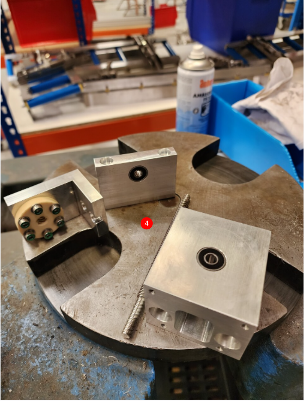
Étape 19 - Assemble leadscrew components
1 Degrease components D0015208 Leadscrew Bearing Block, D0015207 Outer Bearing Housing and 2 off B0001123 Double angular contact bearings
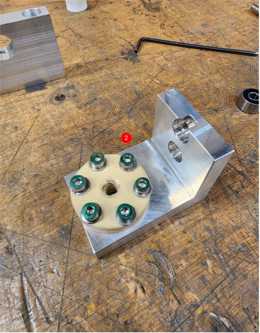
2 Attach B0001185 Leadscrew nut Igus to D0015209 Leadscrew Attachment Bracket and use 6 off M4 x 20 socket caps and A form washers to fix as shown
3 Check fitment of D0015777 Leadscrew SY as shown. Leadscrew should turn through nut with very little resistance
4 Observe correct bearing fit and use loctite 641 . insert B0001123 Double angular contact bearings into D0015208 Leadscrew Bearing Block and D0015207 Outer Bearing Housing
5 Combine assembled parts as shown
Étape 20 - Assemble leadscrew components

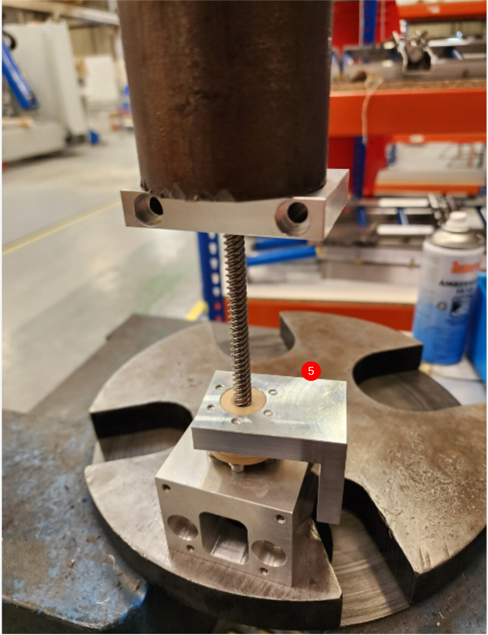
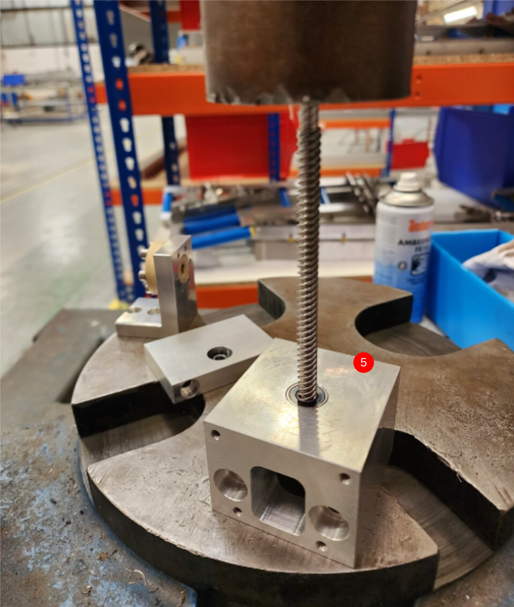
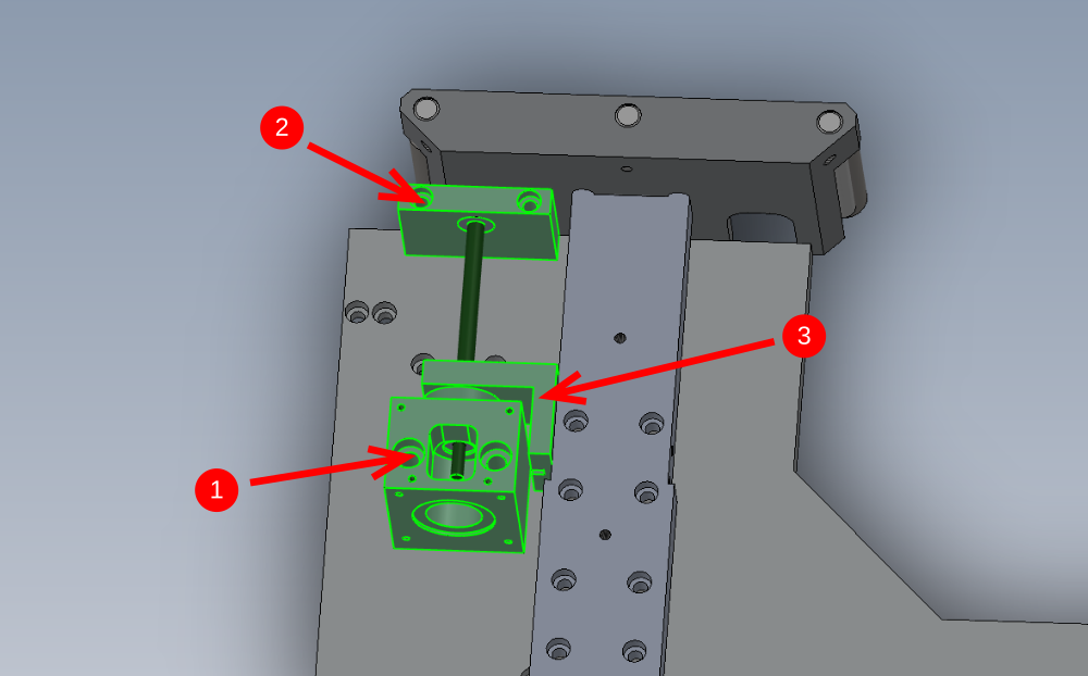
Étape 21 - Mount leadscrew assembly
Mount leadscrew assembly as shown to centralise plate
Use
1 2 off M8 x 70 socket caps
2 2 off M6 x 50 socket caps
3 2 off M6 x 16 socket caps


Draft
 Français
 English
 Deutsch
 Español
 Italiano
 Português