Instructions for correct assembly of Notching gearboxes


Difficulté
Difficile
Durée
1 heure(s)
Sommaire
- 1 Introduction
- 2 Étape 1 - Q/C Bevel Gears
- 3 Étape 2 - Q/C Hardened parts
- 4 Étape 3 - Degreasing of components
- 5 Étape 4 - Assemble 1st bevel gear assembly
- 6 Étape 5 - Fit key and spacer
- 7 Étape 6 - Fit bevel gear and top bearing
- 8 Étape 7 - Fit Castle nut
- 9 Étape 8 - Fit 1st bevel gear assembly to housing
- 10 Étape 9 - Check rotation of assembly.
- 11 Étape 10 - 2nd Bevel gear assembly
- 12 Étape 11 - Checking and adjusting drive dog spacer
- 13 Étape 12 - Checking gear alignment of 1st and 2nd bevel gear assemble
- 14 Étape 13 - checking alignment stage 2
- 15 Étape 14 - Final Assembly
- 16 Étape 15 - Greasing
- 17 Étape 16 - Identification and traceability
- 18 Commentaires
Introduction
For longevity and correct running , it is imperative these units are assembled to the correct tolerances and assembled in the way detailed by this procedure
Tools required
Standard Hex Key Set
Castle nut spanner
Loctite 243 thread lock
Loctite 641 bearing fit
Mandrel jig
Grease applicator
Fe10 solvent spray
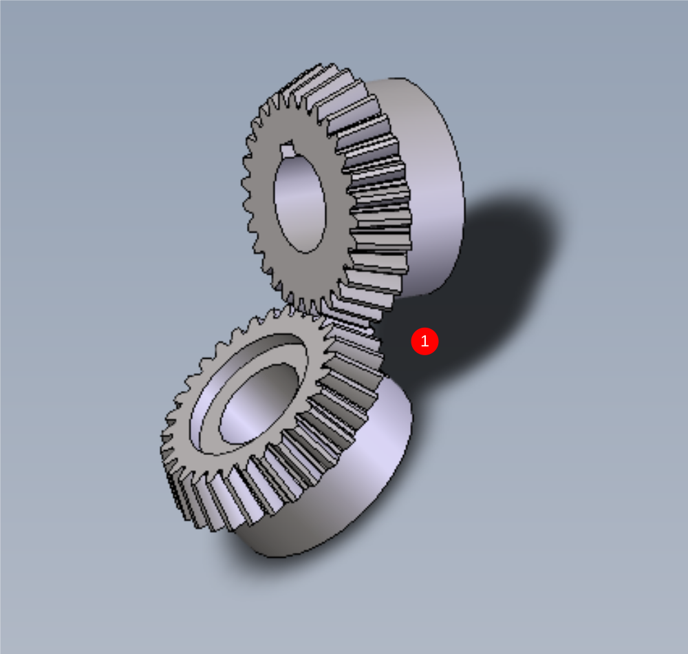
Étape 1 - Q/C Bevel Gears
1 Supplied drive gear D0008177 and D00008178 should be inspected for the following
- Evidence of damage to drive gear teeth, such as burrs or impact points.
- Cleanliness check. There should be no contaminants on the gears
Report any damage to gears through NCR system to log and retrieve replacement gears
Any rust/ surface contaminate should be removed with a wire brush
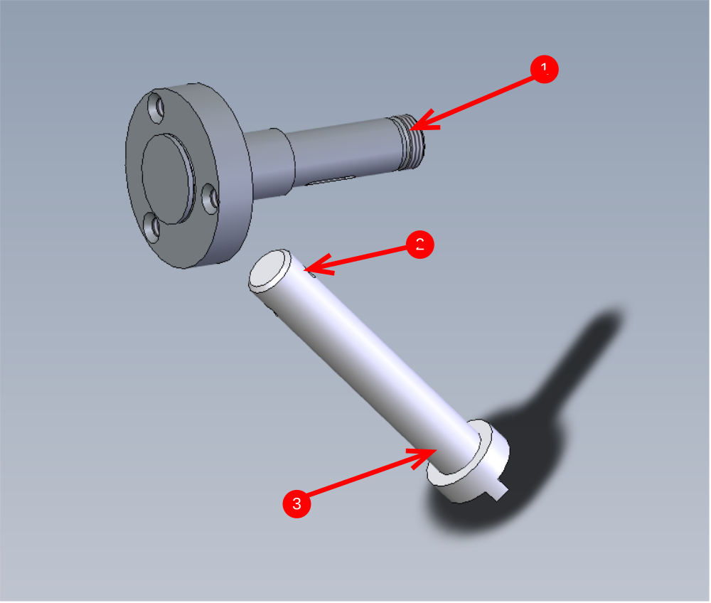
Étape 2 - Q/C Hardened parts
Drive shafts D0008155 and D0008156 should be inspected for the following
1 Damage to indicated thread
2 Presence of burrs on roll pin hole
3 Contaminates from hardening
Damage to thread should be reported by NCR system and replacement sourced
Burrs should be removed by file
Contaminates should be removed with Scotch brite pad
Étape 3 - Degreasing of components
It is vital for correct function that all the shown components are thoroughly degreased before assembly .
To do this, wash all parts with FE10 solvent spray and dry with airline.


Étape 4 - Assemble 1st bevel gear assembly
1 Check plate D0008158 for any number etching. If it is present it should always be assembled with the etching to be on the face shown
2 Mount plate over drive dog D0008155 , and then press bearing B0000043 onto shaft to encapsulate the plate. When the bearing is fitted the plate should still be free to move in the gap left

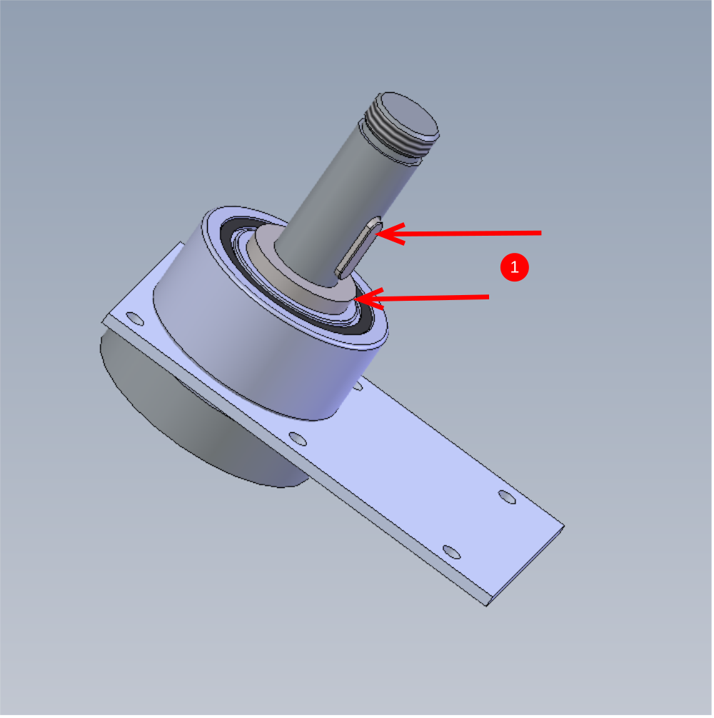
Étape 5 - Fit key and spacer
Fit D00008159 Spacer on top of bearing and then fit B0000256 key to keyway on shaft
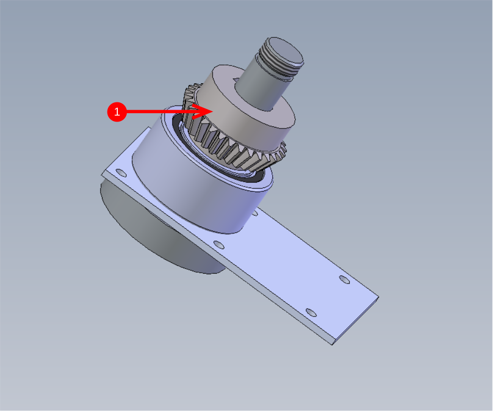
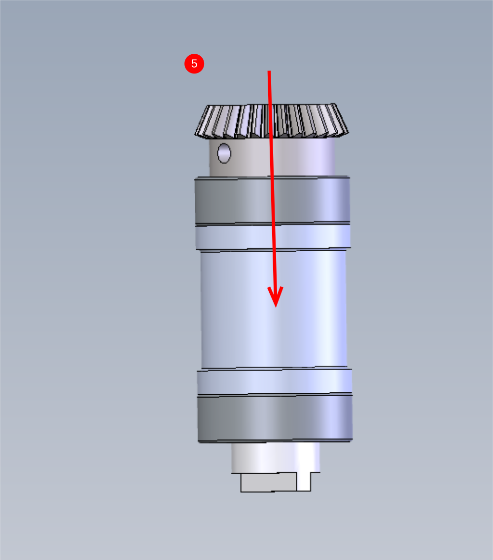
Étape 6 - Fit bevel gear and top bearing
1 Fit bevel gear D0008177 onto assembly orientated as shown
2 Fit Bearing B0000106 to top of shaft as indicated remembering to check fit of bearing
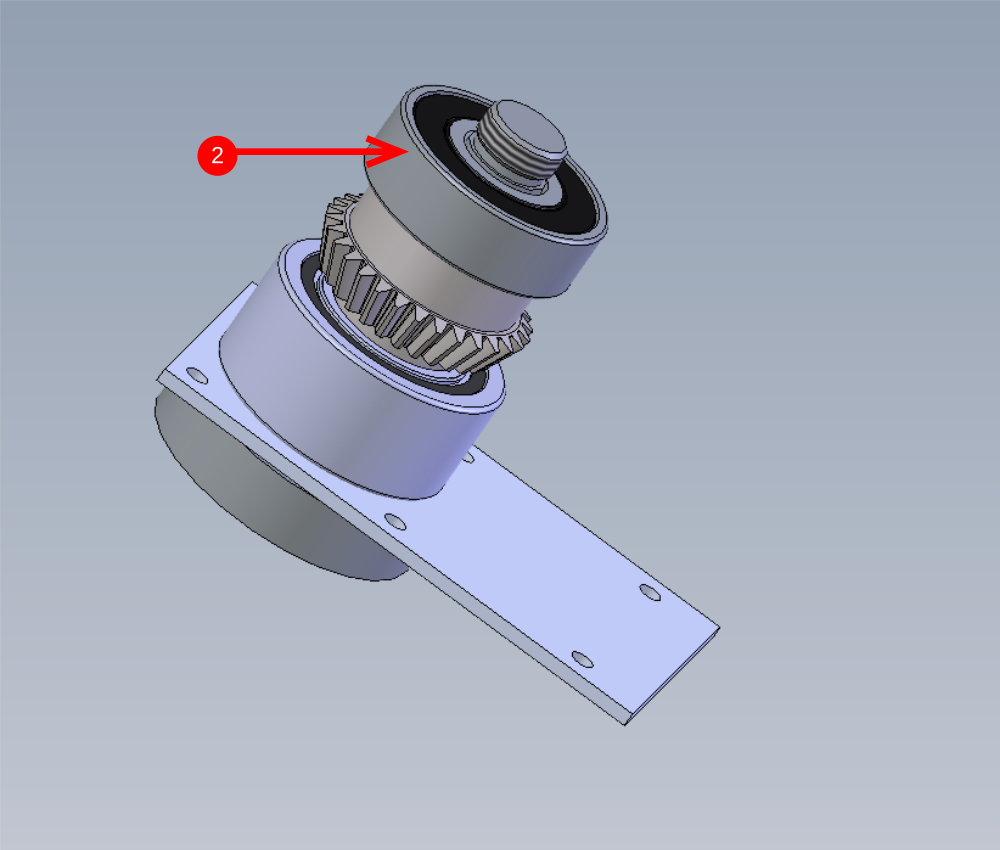
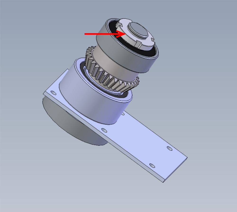
Étape 7 - Fit Castle nut
Castle nut will need fair tension to correctly hold the assembly together
It is best to hold the assembly in a vice to enable the nut to be tensioned correctly.
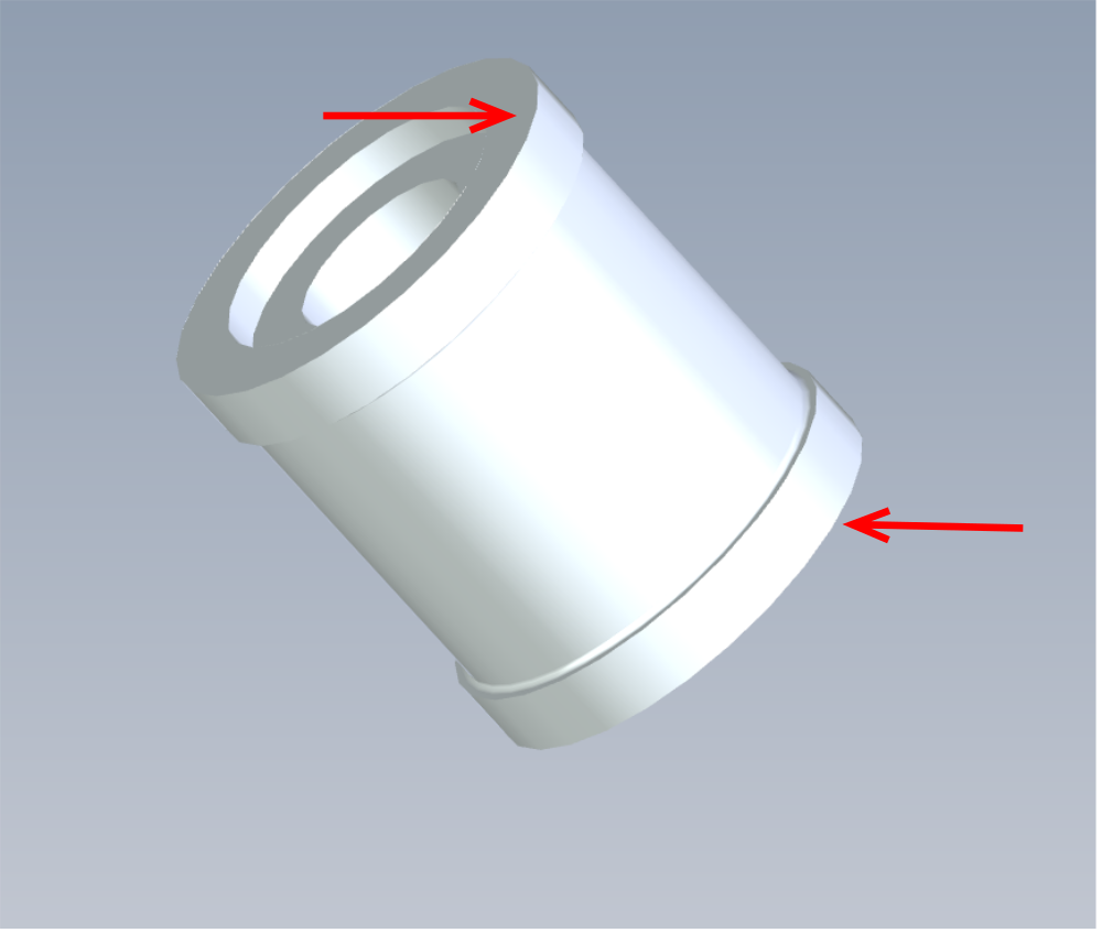
Use loctite 243 on castle nut and use correct castle nut spanner to tension.
Ensure castle nut is fitted in the orientation shown. Larger flat face should facing outwards, smaller face should contact bearing
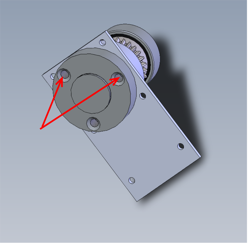


Étape 8 - Fit 1st bevel gear assembly to housing
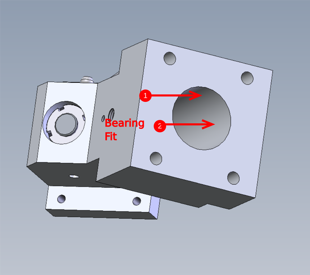
1 Add 3 match head sized drops of bearing fit to indicated bore of D0008154 and smear around
2 Add 3 match head sized drops of bearing fit to indicated bore and smear around
3 Insert by hand 1st bevel gear assembly into bore, there should be slight resistance but no more pressure than hand pressure should be required. 4 Ensure assembly is pushed fully in then captivate with 6 off m3x10 cap head bolts with no washers with loctite 243. Once tight pen mark bolts to shown completed


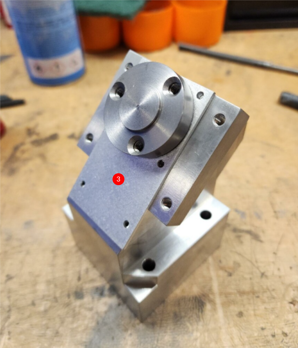

Étape 9 - Check rotation of assembly.
Once all fitted rotation of assembly in housing should be checked . Rotation should be smooth and consistent with no high spots or lumps

Étape 10 - 2nd Bevel gear assembly
1 Press B0000106 bearing one onto shaft. If fit of bearing is not correct , measure shaft and check to drawing D0008156. Report via NCR is out of tolerance . If in tolerance use bearing fit if loose and polish shaft is bearing is tight
2 Fit D0008157 drive dog spacer and 2nd B0000109 bearing again noting the fit of the bearing on the shaft
3 Fit D0008178 bevel gear orientated as picture and align 4mm hole through gear and shaft
4 Use a 4mm x 26mm spiral pin to fix bevel gear to drive shaft


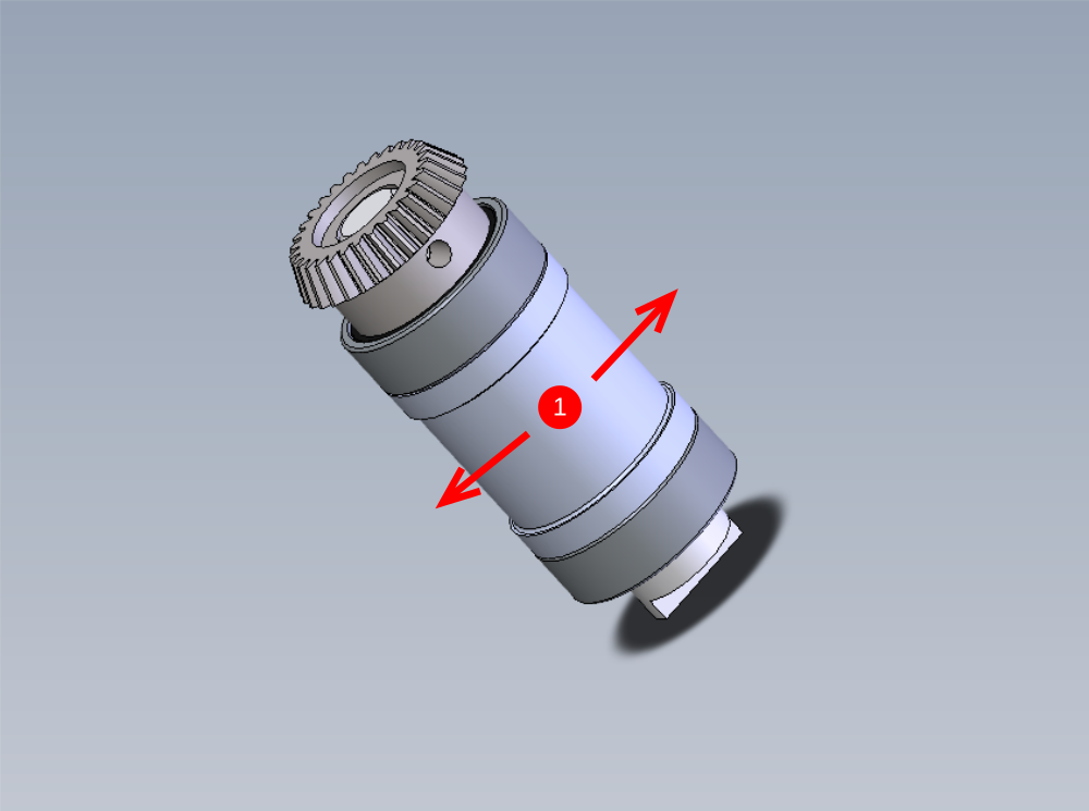
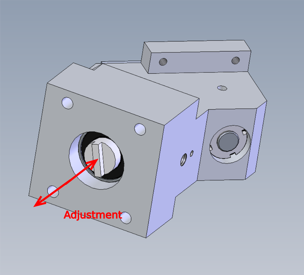
Étape 11 - Checking and adjusting drive dog spacer
1 Spacer should be able to move in the directions shown, but it must have resistance, such as it wont fall under its own weight .
2 If the spacer is to tight, the drive dog spacer will need reducing in size slightly to correct the fit. To do this, disassemble the parts by removing the spiral pin, bevel gear and first bearing and releasing the drive dog spacer.
3 With a 240 grit sanding pad on a flat surface, use circular motions to lightly relief the face indicated by a minute amount. Repeat on both sides. Remember to only take a small amount of, generally 4 rotations will suffice for safe adjustment
4 Reassemble and check fit of spacer. If its still to tight, repeat above step
5 If the spacer is to loose, the spiral pin may have distorted on assembly. To adjust in this instance, the following is required. Use the press and place the assembly vertically , and using the press apply pressure in the direction shown to help centralise the roll pin
6 If the bearings do not require bearing fit, move to next step. If bearing fit was loose, disassemble components and reassemble with smears of bearing fit for bearings

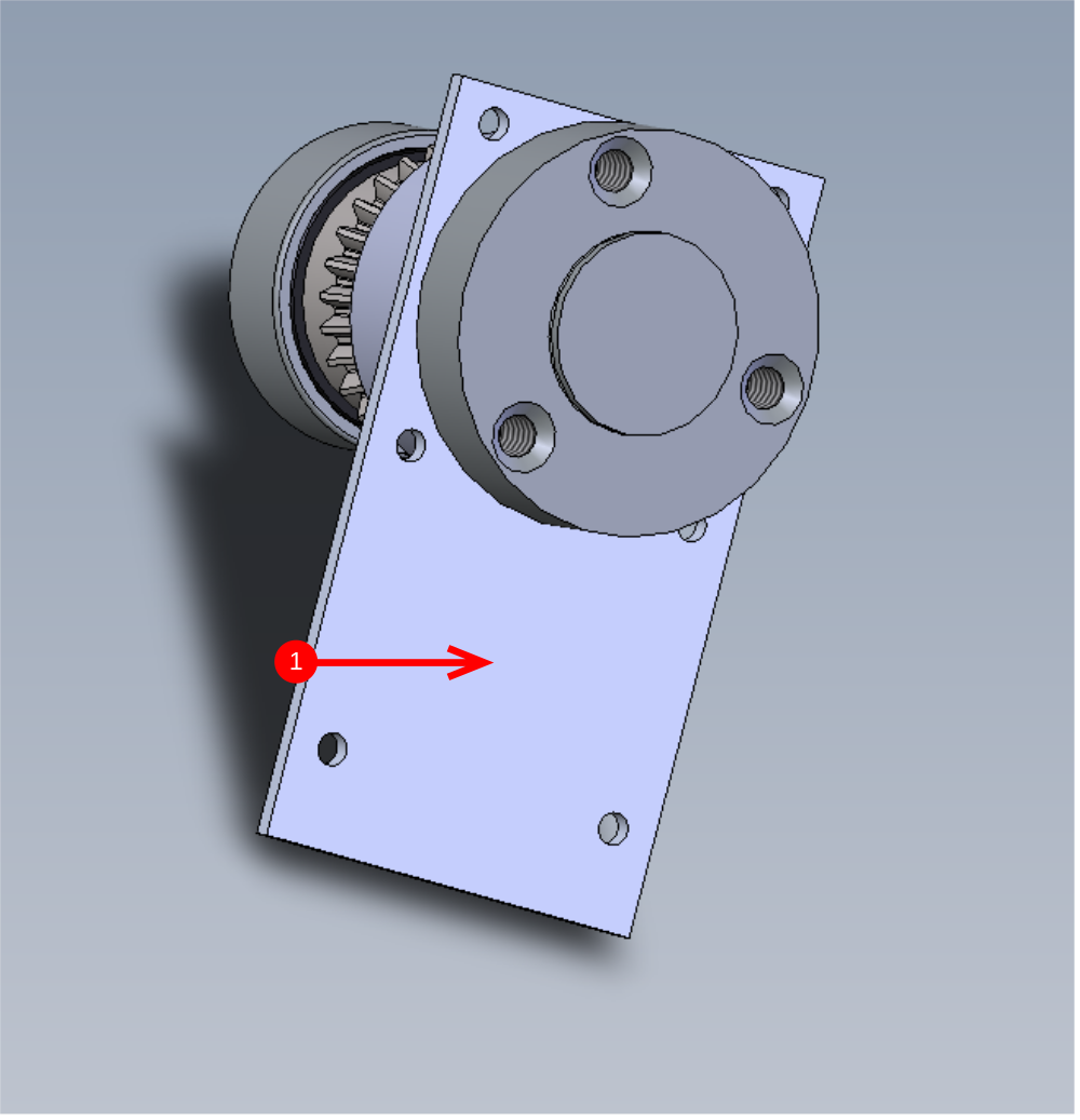
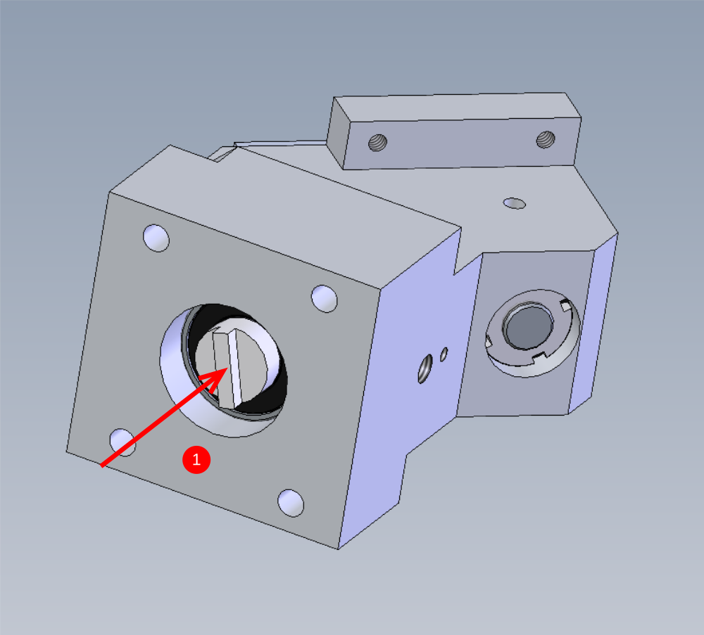
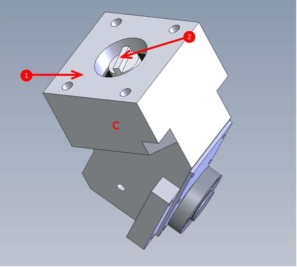
Étape 12 - Checking gear alignment of 1st and 2nd bevel gear assemble
Before final assemble the fit of the bevel gears needs checking .To do this the following should be followed.
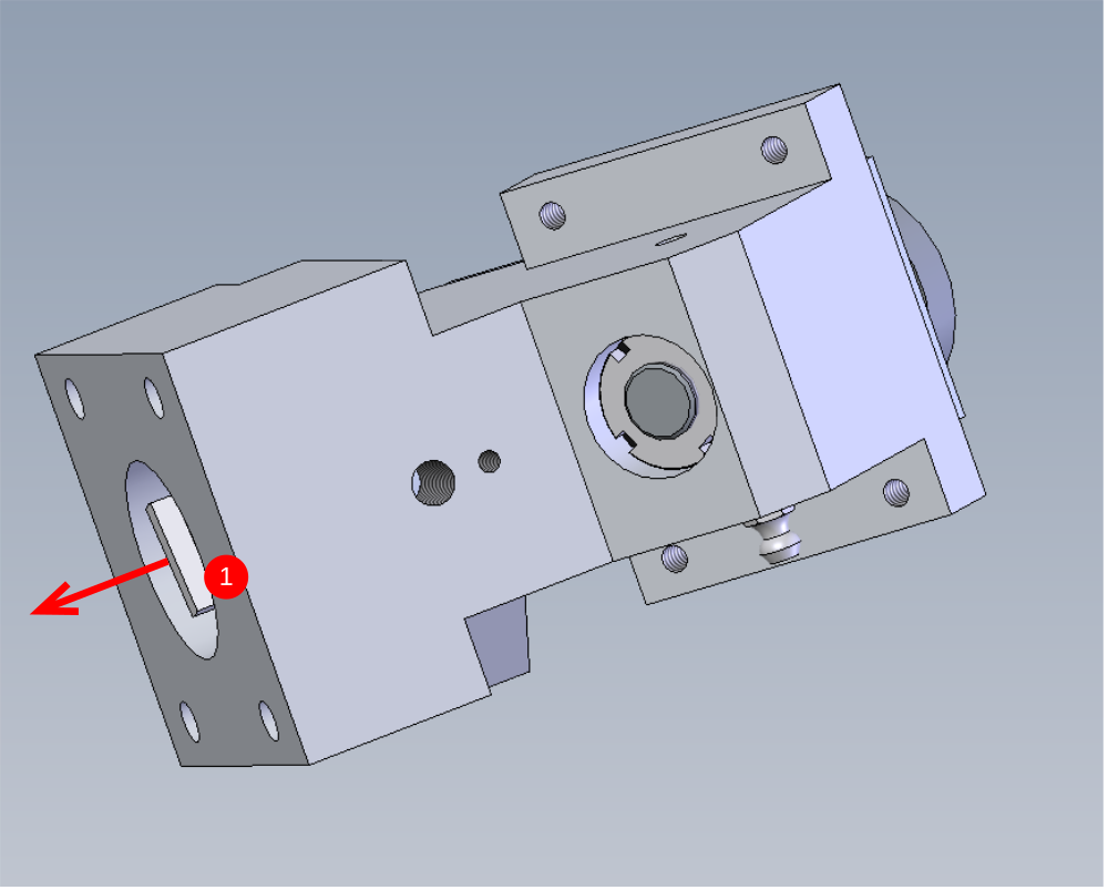
1 Slide the second bevel assembly into the housing in the direction shown. This assembly should be a snug slide fit into the housing . Push the assembly in by hand until it bottoms out on the 1st installed bevel gear.
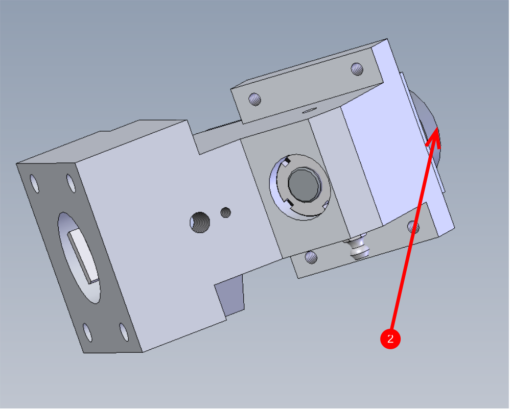
2 Rotate blade mounting face to adjust the bevel gears to a zero backlash position
3 Use a M8 x 12 flat bottomed grubscrew in the indicated hole then gently apply pressure and hold the 2nd bevel gear in place.
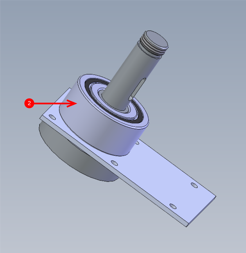
Étape 13 - checking alignment stage 2
The following points should be observed and checked to achieve the optimal setting
A There should be as minimal backlash as possible between the two bevel gears. To check this, hold point 1 by hand to stop rotation and rotate point 2 left and right to check backlash.
B Gear high spots should be checked for by rotating point 1 and making sure sure rotation is even and consistent, with no tight spots.
C Face 2 must be a minimum of 1mm from face 1. If not interference will happen when mating gearbox to drive unit
All of these can be adjusted by moving the depth of the 2nd bevel gear assembly to find the optimum point to hit all the above important criteria

Étape 14 - Final Assembly
Once the previous step criteria has been confirmed as possible, the next step is to finalise this assembly
1 Extract 2nd bevel gear assembly from gearbox housing
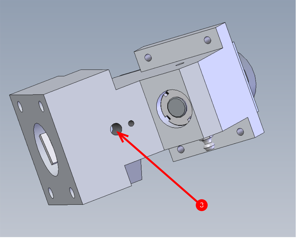
2 Apply 4 match head size drops of bearing fit to indicated points in gearbox housing, and smear around the bore.
3 Reinsert 2nd bevel gear assembly and set into position again using the previous step 13 criteria
4 use a m8 x 12 pointed grubscrew and loctite 243 in indicated hole to lock 2nd bevel gear assembly into position. This grubscrew must be tight.
5 recheck all criteria has been maintained after adding locking grubscrew
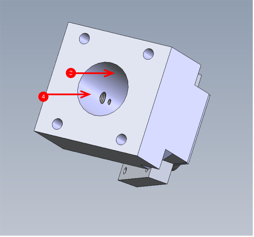

Étape 15 - Greasing
1 Insert grease nipple one as shown
2 Use grease gun and pump grease through above nipple until grease starts to come out of the open grease point as indicated
3 Fit 2nd grease nipple to gearbox
4 Attached running mandrel
5 Attach drill and run gearbox in both directions for a minute each direction
6 Remove one of grease nipple, and again grease other one until grease starts to appear from open greasing point
7 Refit greasing nipple
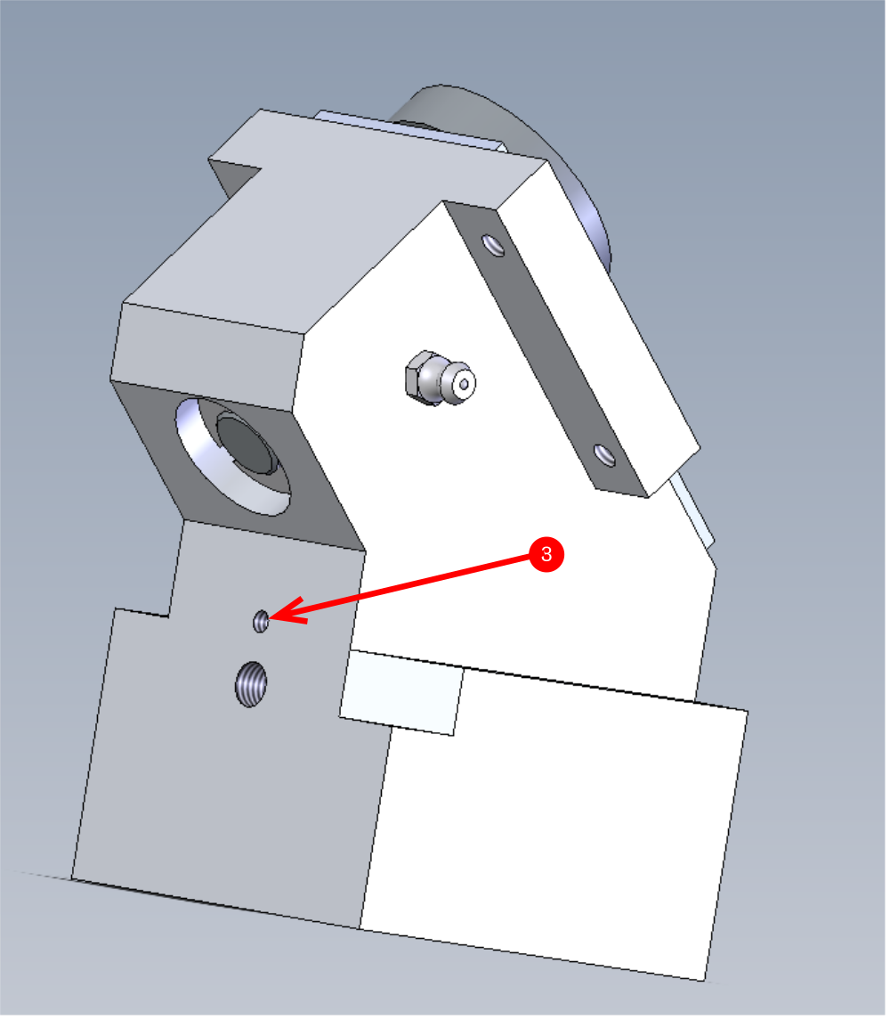
8 Fit m4x 8 blanking grubscrew with loctite 243 to indicated hole


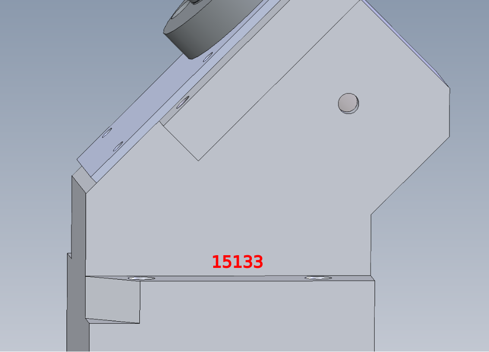
Étape 16 - Identification and traceability
It is now an important part of the build to give the gearbox its identifying serial number
This must be stamped onto the gearbox housing at the indicated point
This number is the works order number that the parts were issued to. All sales orders and machine builds will have a unique number issued for the parts required and this is the number that needs to be stamped into the housing
Draft
 Français
 English
 Deutsch
 Español
 Italiano
 Português