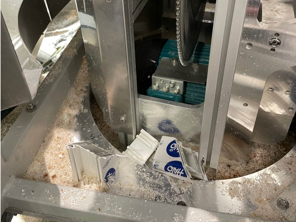
Kit R0019199 contains a kit of components for protecting the SR axis bearing system on an Autoflow. This area is prone to collect offcuts which can pull the seal from the SR axis bearing

Difficulté
Difficile
Durée
6 heure(s)
Sommaire
- 1 Introduction
- 2 Tutoriels prérequis
- 3 Étape 1 - SR Axis Datum Assembly Move
- 4 Étape 2 - Move SR Stop Block up high
- 5 Étape 3 - Remove 40x80 uprights
- 6 Étape 4 - Reinstate new posts
- 7 Étape 5 - Remove existing SR Stop Assy
- 8 Étape 6 - Fit slewing ring grease fittings
- 9 Étape 7 - Install the grease manifolds
- 10 Étape 8 - Fit ring segments
- 11 Étape 9 - Add Low Friction tape
- 12 Étape 10 - Install half moon plates
- 13 Étape 11 - Fit the mount blocks in the T section
- 14 Commentaires
Introduction
This area is prone to collect sharp - cornered offcuts which can pull the seal from the SR axis bearing. The kit will help prevent damage.
Use Kit R0019199 Upgrade: Autoflow Slewing Ring Guard Kit
- Tutoriels prérequis
Tutoriels prérequis
Étape 1 - SR Axis Datum Assembly Move
This procedure must be done in conjunction with moving the SR Axis Datum to a position higher and ant the front of the machine to Move SR Datum Sensor to Higher Level R0019217

Étape 2 - Move SR Stop Block up high
Loosen off bolts that hold SR stop block and move stop block as high as possible, to keep out of the way.
Remove existing SR end stop assy.
Étape 3 - Remove 40x80 uprights
Within the SR axis, there are two 40x80 uprights . These are each attached with 4 caphead bolts within the vertical side plates, 2 capheads from under the machine, and 2 countersunk bolts on the cut table.
All of these bolts need removing, and the posts can then also be removed.
Étape 4 - Reinstate new posts
New posts are then to be reinstated. These will look similar to the ones removed, apart from a 40mm x 90mm section removed from the lower part of each upright. The cutout also needs to be on the outboard side.
For reference, this cut out is to allow the fitment of the 3D printed guard segments.
Étape 5 - Remove existing SR Stop Assy
The original SR axis stop on a Mk4 machine was a bit of an afterthought and can be made up from various spacers and washers.
- On a Mk4 VS machine, the SR axis stops are both located on a single D0016356 on the outfeed side of the machine - this allows 270 degrees of rotation before the end stop.
- On a Mk4 non-VS machine, a D0016356 will need to be fitted to infeed and outfeed side so the 135 stop and 45 stop can be fitted on each side.
- On a Mk3 machine, the existing stop should be ok.
Étape 6 - Fit slewing ring grease fittings
Install 90 degree grease fittings to ring (4 off). Ensure all facing upwards.

Étape 7 - Install the grease manifolds
Install grease manifolds, complete with yellow grease line tail, into the 90 degree grease fittings. The manifolds should sit flush on the Saw base plate. If they don’t, remove the yellow grease line and trim very small amount off it and try again until the manifold sits flush.
Test out the grease lines by greasing the slewing ring through the new grease line assemblies. Test all 4 to check for leaks and function.
Étape 8 - Fit ring segments
Fit ring segments one by one around SR ring. (picture shows the system fully fitted)
Last segment WILL be a tight fit. Due to the way the end faces of each segment angle in towards the centre axis, the last segment will need to come in from above and outboard of the 7 other segments and “wedge” its way into position. Be very careful installing this segment. The way the segments are printed mean that they are inherently slightly weaker along their print planes, so can delaminate if overstressed. The best way to install this final segment is to ease it into the correct position and gentle tap downwards, side by side, until it is in position.
Note: The way the segments lock together is similar to a jigsaw. It’s worth noting that the final segment will have to be one of the segments with the holes to screw it down. This is because these segments hold the manifold segments down, by design.
Once all 8 segments are in place, drill and tap for M3 through the holes in the “pull down” segments. There are 2 holes per segment, so 8 tapped holes are needed, although if access is tricky, just one tapped hole per segment is acceptable.
Install M3x10 caphead bolts, plus M3 washers into these tapped holes, to hold the segments in place.

Étape 9 - Add Low Friction tape
The tape is to provide a sliding surface for the cover to slide over the aluminium plate below
Cut into 8 strips , and add one to each of the tops of the plastic ring segments.
Étape 10 - Install half moon plates
Position the 2 “half moon” stainless plates into the SR assy. The outer edge of the plates should rest neatly into the rebate on the 3D printed SR guards. The inner contours of the plates fit around the upright posts of the SR assy. Note that the cables running up to the ethercat box will need to be carefully routed through a gap left between the two half moon plates.

Étape 11 - Fit the mount blocks in the T section
Fit
4 off M0001050 M6 Mount block as shown
4 off F0000529 T Nuts
4 off F0000013 M6x16 Cap Screws


Draft
 Français
 English
 Deutsch
 Español
 Italiano
 Português