Laser Upgrade on an Ecoline

- Run a datum test on a piece of large outer to check the current status of machine.
- Switch power off
- Remove Datum on ring plates
- Replace 4 off M8x25 bolts.
- Check machine stroke. Lift outfeed clamp and pull gripper through ring to end of travel. The gripper base needs to get to within 3mm of touching the bottom infeed roller closest to the spindles. To get more movement, adjust the X axis end stop damper, or for more adjustment reposition the damper mounting bracket.
- Remove R axis Datum mount bracket
- Disconnect R axis limit sensors from the connection box. The X7 input will eventually be used for the laser
- Ensure the R axis connection box has 3 holes around 7mm diameter to take the 3 wires
- Assemble the detector E0361 (large lens) into part D3974.
- If the current X6 sensor is the threaded type, it will fit in the new bracket. If the sensor is the smooth barrel type, it will need replacing from the supplied kit.
- Assemble emitter E0360 into part D3975. Fit D3975 to D3994.
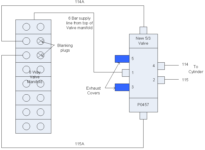
- Fit new 5/2 valve with M4 studding
- Repipe the infeed pull pneumatics according to diagram
- Repipe infeed blowers into top slice of 8way manifold using an 8mmY. This output used to be used for the Grip Steady, and then the Y notch blower. These functions are now redundant.
- Drop the infeed swarf chute to aid access. Note to help easy removal, put an allen key in the guard mounting hole after removing the bolt. This will stop the chute from falling down and smashing the air fittings on the support cylinder. Get someone to lend a hand at this point because the guard is difficult to handle.
- Run a blower pipe to the lower laser mount.
- Remove the R axis cover plate D6061. Retain to return to Stuga
- Fit the laser mount with new R axis cover plate D3994
- Thread the bottom laser cable as photograph
- Connect the X6 cable (if required from point 7) and the Laser connection leads in the r axis connection box as shown


- You will need someone now to give you a hand lining the laser up
- Focus the laser beam with the supplied spanner at the work height on a piece of card. You are looking for the smallest possible dot.
- Draw a line on a small piece of card and wedge it under the laser receiver. Line up the laser emitter direction with the line on the card in the Y axis plane and tighten off with the locknut.
- Check that the laser is not leaning away from the ring – it should be 5mm away from the ring plates
- Test on IO screen – X7 Red when beam is broken
- Fit dust cover D3977 and D3976 and pipe in the blower.
Mechanical Parts to return to Stuga
1 off D3158 R Axis Datum Mount Bracket
1 off D6061 R axis cover plate
Software:
- Copy ecoline folder to c:\My Documents\Trio Projects
- Install Trio via MotionPerfect (LOAD the software into controller)
- Copy ecoMessages.mdb to c:\Program Files \Stuga
- Copy ecoline.mdb version 5.41 or above to c:\Program Files\Stuga.
- Make a copy of ecoMachineData for backup
- Open ecoMachineData.mdb, then tblParameters
- Set the following parameter values
| ParamName | ParamValue |
| squareadjustment | 0 |
| mitreadjustment | 0 |
| DatumOnRing | 0 |
| measurePoint | -50 |
| YFRMeasure | 400 |
| YRRMeasure | 400 |
| Xloadpos | 0 |
- Additional parameters (if not there already):
| ParamName | ParamValue | VRNo | ParamType | Description |
| Minable clamp | 50 | 260 | Program Setup | Set profile width for it to work upto |
| V notch X offset Len | 0 | 261 | V Notch Setup | What length does offset need to work upto |
| V notch X offset Val | 0 | 262 | V Notch Setup | amount of offset applied on first cut for the above length |
| Rear Left Y offset | 0 | 264 | V Notch Setup | Offset for depth of first Y notch Cut on Left Y notch |
| Rear Right Y offset | 0 | 265 | V Notch Setup | Offset for depth of first Y notch Cut on Right Y notch |
| Rear V cut type | 0 | 266 | V Notch Setup | 1= U/T/D 0 = U/D/T/U/D |
| laserAdjustment | 7 | 267 | Measurements | Distance of laser to spindle c/l. Adjust for X position |
| Infeed Overrun | 20 | 268 | Measurements | Overrun of infeed pull after laser point |
| Minimum X Position | -35 | 269 | Measurements | Minimum position that X axis can reach before crashing |
| Gripper Depth | -20 | 270 | Measurements | Amount of grip in Material |
| GripperToSpindle | 14 | 271 | Measurements | Amount from end of gripper to center of spindle at Datum Position (X=0) |
- Install Baldor Nextmove Workbench ver 5225
Setting Up
- In axis parameters, set X Datum pos to 0
- Redatum machine
- Press Estop
- Move the R, Y and Z to touch gripper with end of a cutter. Mark the point on the gripper with a marker pen
- Measure the distance from the mark to the end of the gripper nose. Put the value in the parameter GripperToSpindle. Should be around 17mm
- Refer to picture. Wind Y axis until you see laser draw a line up the side of the gripper base. Prop a rule against the gripper to enable you to measure the distance from laser point to the spindle centerline (black mark) +/- 0.5mm. Put the value in the parameter laserAdjustment. It should be between 5 and 9mm
- Mark where the X axis is currently (“Zero”). Then slide the X axis by hand to the mechanical end stop. Measure the distance moved from “Zero”. Subtract 2mm and put a minus in front. This is the parameter Minimum X Position. Should be around –37mm.
- Set xloadpos=75
- Take a square end piece of outer frame, draw a series of lines at 15mm, 20mm, 25mm and 30mm from the feed end using a square. This will act as a rule to set the infeed overrun parameter.
- Run the bar through with a datum test.
- At the point when the bar breaks the laser, press estop. The cutter will line up with one of the lines that has been drawn on the profile. Subtract the laserAdjust distance
- Run a datum test – especially if the datum switch has been changed.
Draft
 Français
 English
 Deutsch
 Español
 Italiano
 Português