How to diagnose TwinSAFE problems
Auteur  Gareth Green | Dernière modification 11/11/2025 par Gareth Green en cours de rédaction ⧼frevu-button-review-label⧽
How to diagnose TwinSAFE problems
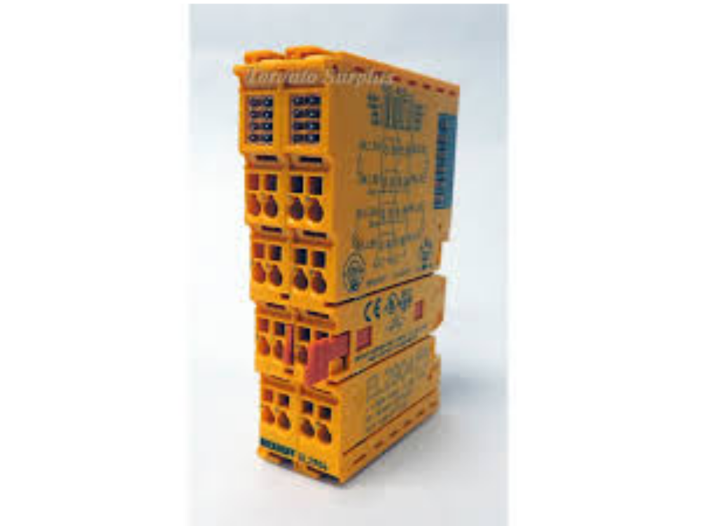
Confluence Diagnosing_TwinSAFE_Issues_-_Advanced_EL2904.jpg
11/11/2025 Moved to Confluence
Click here en none 0
Draft
Vous avez entré un nom de page invalide, avec un ou plusieurs caractères suivants :
< > @ ~ : * € £ ` + = / \ | [ ] { } ; ? #
 Français
 English
 Deutsch
 Español
 Italiano
 Português