| [version en cours de rédaction] | [version en cours de rédaction] |
| Ligne 1 : | Ligne 1 : | ||
{{Tuto Details | {{Tuto Details | ||
| − | |Main_Picture=ZX5_Production_R0000548E_Module_G_to_R0015040_Module_F_alignment_Screenshot_2023-12- | + | |Main_Picture=ZX5_Production_R0000548E_Module_G_to_R0015040_Module_F_alignment_Screenshot_2023-12-21_081410.png |
| − | |Main_Picture_annotation={"version":"2.4.6","objects":[{"type":"image","version":"2.4.6","originX":"left","originY":"top","left":- | + | |Main_Picture_annotation={"version":"2.4.6","objects":[{"type":"image","version":"2.4.6","originX":"left","originY":"top","left":-5,"top":56,"width":1400,"height":797,"fill":"rgb(0,0,0)","stroke":null,"strokeWidth":0,"strokeDashArray":null,"strokeLineCap":"butt","strokeDashOffset":0,"strokeLineJoin":"miter","strokeMiterLimit":4,"scaleX":0.43,"scaleY":0.43,"angle":0,"flipX":false,"flipY":false,"opacity":1,"shadow":null,"visible":true,"clipTo":null,"backgroundColor":"","fillRule":"nonzero","paintFirst":"fill","globalCompositeOperation":"source-over","transformMatrix":null,"skewX":0,"skewY":0,"crossOrigin":"","cropX":0,"cropY":0,"src":"https://stuga.dokit.app/images/e/eb/ZX5_Production_R0000548E_Module_G_to_R0015040_Module_F_alignment_Screenshot_2023-12-21_081410.png","filters":[]}],"height":449.7607655502392,"width":600} |
|Description=<translate>Details for alignment of module G to F inclusive of additional safety tray fitting</translate> | |Description=<translate>Details for alignment of module G to F inclusive of additional safety tray fitting</translate> | ||
|Categories=Production | |Categories=Production | ||
Version du 21 décembre 2023 à 10:14
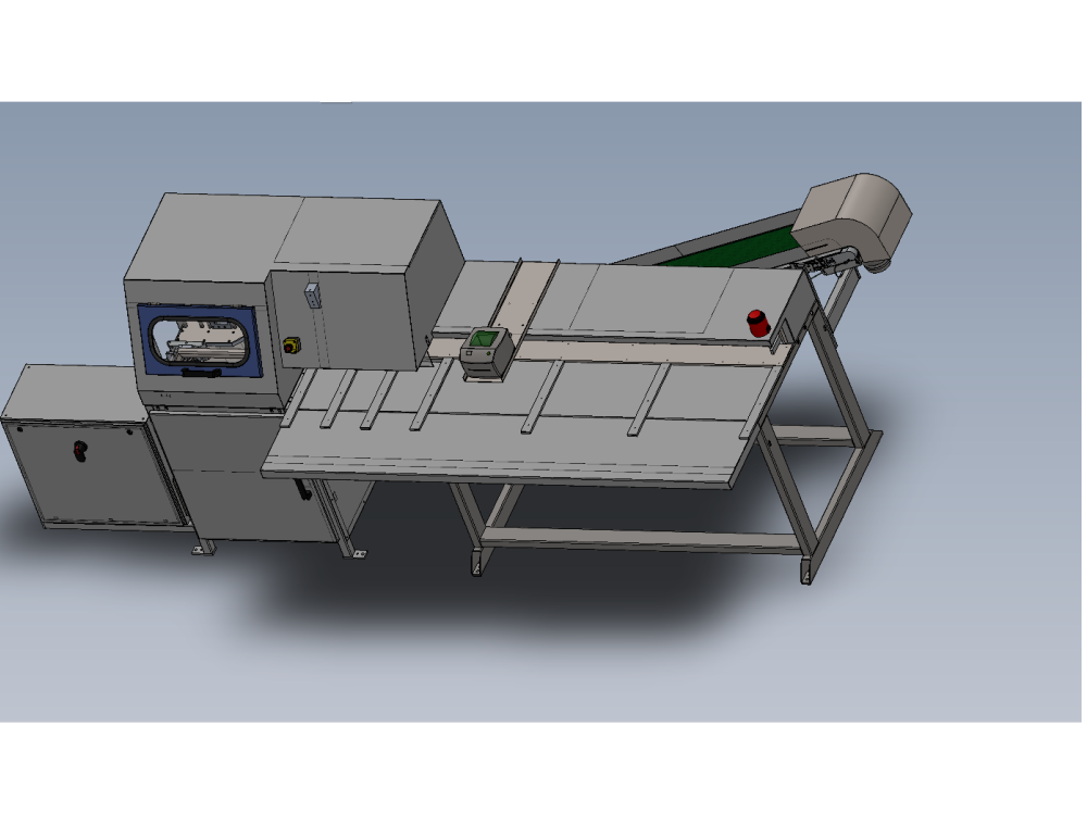
Details for alignment of module G to F inclusive of additional safety tray fitting

Difficulté
Moyen
Durée
3 heure(s)
Sommaire
- 1 Introduction
- 2 Étape 1 - Position saw outfeed table
- 3 Étape 2 - Saw Outfeed table levelling
- 4 Étape 3 - Saw outfeed height adjustment and Y axis position
- 5 Étape 4 - Fix frames together with M10 set bolts and washers
- 6 Étape 5 - Fit Swarf conveyor
- 7 Étape 6 - Swarf conveyor blower connection
- 8 Étape 7 - Prepare front tray
- 9 Étape 8 - Mark Tray and drill
- 10 Étape 9 - Attach tray
- 11 Commentaires
Introduction
Details for correct alignment of module G to module H
Étape 1 - Position saw outfeed table
Approximately position saw out feed table against saw module Leave a 10mm gap between frames until levelling has been completed
Use black floor pads 4 off under adjustment bolts
(please note image shows safety tray fitted, this is an error and will not be fitted until later steps )

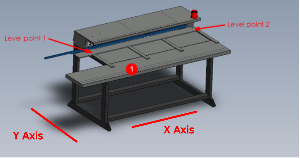
Étape 2 - Saw Outfeed table levelling
- X axis of module is levelled from the two indicated points . Use a 2 meter straight edge between these points and an engineers level on top
- y axis is levelled from these two indicated points . an engineers level rested on this face is sufficient for levelling

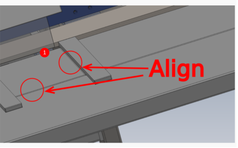
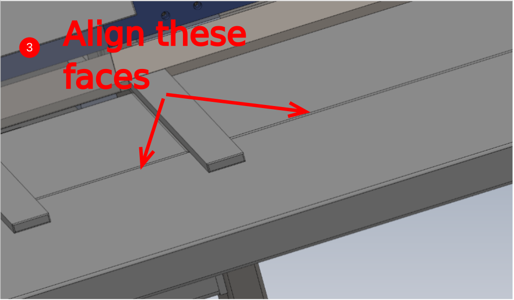
Étape 3 - Saw outfeed height adjustment and Y axis position
1 Adjust height of saw outfeed table to align faces shown
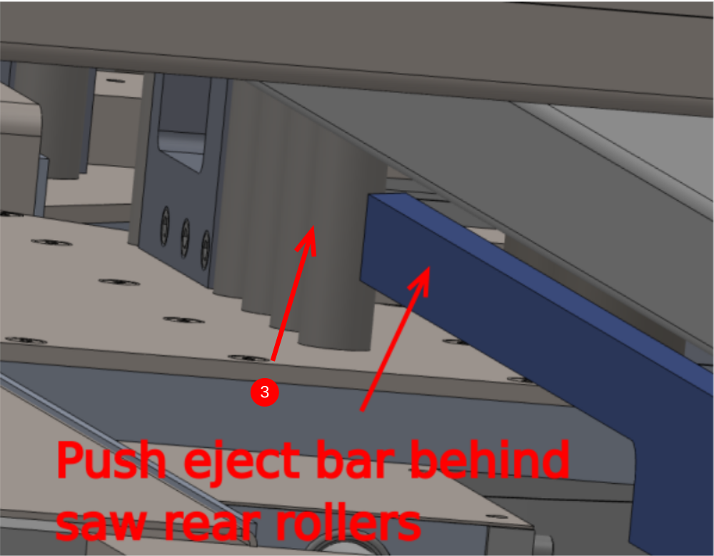
2 Check that eject table cylinder can freely move beneath frame on full range of travel
3 Align front faces of saw and outfeed frame to be inline
Check that Blue push bar is behind Saw rear fence rollers by at least 5mm( Adjustment is possible if not via slots on push bar assemblies )
Étape 4 - Fix frames together with M10 set bolts and washers
1 Fix frames together with M10 x 100 set bolts, 3 off Large M10 washers stacked on each bolt and a M10 nut on each bolt
2 Connect 8mm Blue airpipe from saw module F to valve bank on outfeed
Étape 5 - Fit Swarf conveyor
Fit waste conveyor to out feed frame using 2 off M8 socket caps
Adjust waste conveyor feet to minimise gap shown between saw module rear panel and waste guide on conveyor


Étape 6 - Swarf conveyor blower connection
Connect swarf conveyor blower feed to saw module bulk head

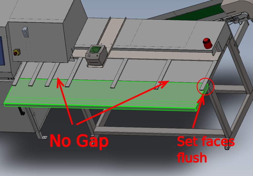
Étape 7 - Prepare front tray
Use red pump trolley to lift tray into position
Set end indicated flush
Ensure tray is pushed up against both saw and outfeed frame

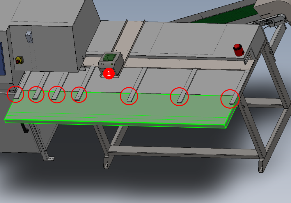
Étape 8 - Mark Tray and drill
1 Pencil mark around 7 off arms
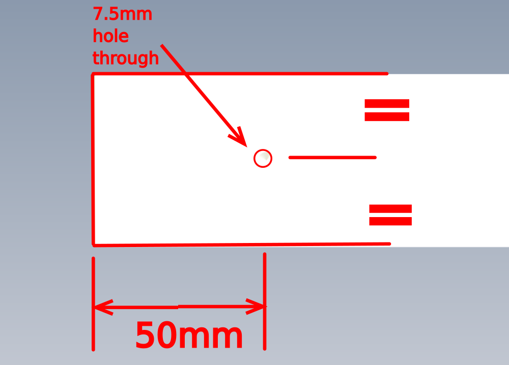
2 Remove tray and mark hole position as shown on each mark point on tray
3 Pilot and open to 7.5mm at each marked position
Étape 9 - Attach tray
1 Reposition tray with red trolley
2 Fit tray with 7 off M6 socket caps and heavy M6 washers
Draft
 Français
 English
 Deutsch
 Español
 Italiano
 Português