Additions to ZX5 machine to enhance operator safety from Z084

Safety Measures Added
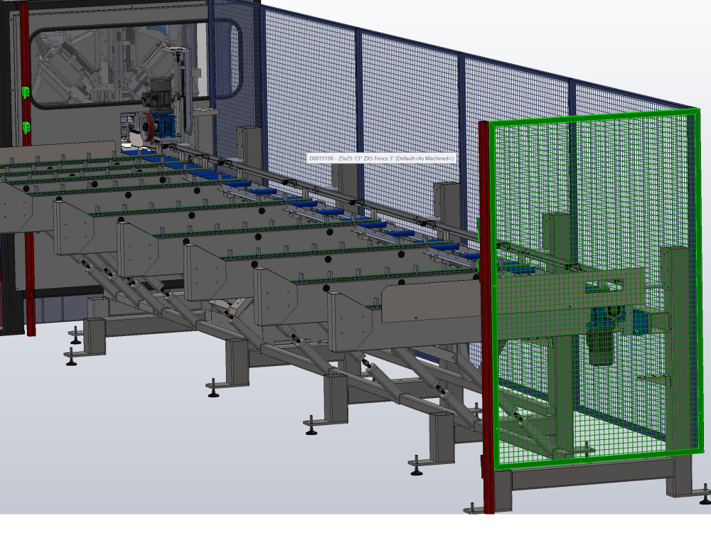
To protect accidental operator access to hazardous areas of the infeed table, a light beam and side fence have been added
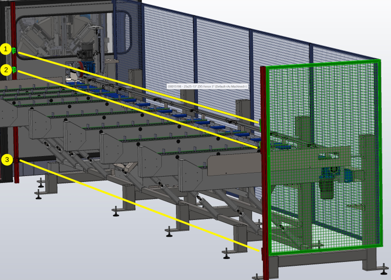
Beams 1 and 2 detect when the operator leans in to the machine when loading bars, beam 3 detects the operator crawling under the fixed barrier. The side fence prevents access to the infeed drive mechanism from the side
The system is separate from the main emergency stop circuit, in that it only isolates the local hazards in the infeed table, brought about by the Infeed Conveyor and infeed wheel. The system is also linked to a slowdown input on the x axis drive so that any rapid movements of the profile in a reverse direction are reduced.
Control Circuit
The beams are electrically linked via a system of relays to the motor drive components. Breaking any beam will cause both motors to immediately stop by interrupting the "Fwd" and "Rev" inputs to the VSS drives for these motors. Depending on the sequence running at the time, the control system will recover automatically, or may need an operator intervention to restart (Press start). The interventions are kept to a minimum to enable continuous flow of the machine during loading, but there may be specific circumstances where a restart is necessary
The top beams 1 and 2 are connected in series.
To add an additional layer of safety monitoring, the PLC also applies diagnostic testing by scanning the inputs and a feedback signal from each drive.
- Check if beams are permanently broken (Faulty or misaligned beam)
- Check that Motor run signal is off when beam broken (Faulty relay switching circuit)
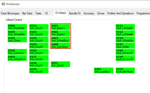
The inputs can be diagnosed on the IO Service screen
| IORef | Description | State |
|---|---|---|
| X465 InA_Beam1 | Top Beam Made | Normally High
Low when either top beam broken |
| X466 InA_Beam2 | Lower Beam Made | Normally High
Low when bottom beam broken |
| X467 InA_WheelRun | Infeed Wheel Running | High when wheel is in motion |
| X467 InA_ConvRun | Infeed Conveyor Running | High when conveyor motor is in motion |
Fault Codes
| Code | Title | Description | Rectification |
|---|---|---|---|
| 229 | Lightbeam Diagnostic Fault | One of the motor outputs is running when beam is broken | Check function of relay circuit
Check function of VSS Drive |
| 230 | Lightbeam Top Permanently Broken | One of the top beams is out of alignment or faulty | Check alignment and function via IO screen |
| 231 | Lightbeam Bottom Permanently Broken | Bottom beam is out of alignment or faulty |
Risk Assessment Calculations
- Procedure followed for conducting the risk assessment as per Machinery Directive 2006/42/EC, Annex I, first general principle, further defined in EN ISO 12100 Safety of machinery - General principles for design – Risk assessment and risk reduction; three-stage iterative process for risk reduction
- Assessment of the initial and achieved risk level as per DIN ISO/TR 14121-2 Safety of machinery – Risk assessment – Part 2: Practical guidance and examples of methods, 6.3 Risk graph
- Determining the required performance level (PLr) EN ISO 13849-1 Safety of Machinery – Safety-related parts of control systems – Part 1: General principles for design
- Determining the safety integrity level (SIL) as per EN 62061 Safety of Machinery – Functional safety of safety-related electrical, electronic and programmable electronic control systems
PLr Level defined as (a)

Applying Safety distances from BS EN ISO 13855:2010
- Table1 used to determine safe height of 1400mm (Hazard height 1400mm, distance to hazard 950mm)
- Two beams used for redundancy and coverage
- Additional diagnostics added to PLC code to detect fault in system - not required on PLr=a, but zero cost to add and adds a second level of safety
- EN13855 para 6.2.4 Used to calculate minimum distance S
S = (1600xT)+850
T = 0.1s
S = 910mm
Actual distance on machine = 950mm
Draft
 Français
 English
 Deutsch
 Español
 Italiano
 Português