| [version en cours de rédaction] | [version en cours de rédaction] |
(Page créée avec « {{Tuto Details |Description=<translate>Technical Details of the Saw Y Drive system</translate> |Categories=Specification |Tags=Y Drive, Y Notch, ZX5 }} <translate>= Overvi... ») |
|||
| Ligne 1 : | Ligne 1 : | ||
{{Tuto Details | {{Tuto Details | ||
| + | |Main_Picture=Saw_Y_Drive_Calculations_SY_Axis_measurements.jpg | ||
| + | |Main_Picture_annotation={"version":"2.4.6","objects":[{"type":"image","version":"2.4.6","originX":"left","originY":"top","left":44,"top":-17,"width":618,"height":599,"fill":"rgb(0,0,0)","stroke":null,"strokeWidth":0,"strokeDashArray":null,"strokeLineCap":"butt","strokeDashOffset":0,"strokeLineJoin":"miter","strokeMiterLimit":4,"scaleX":1.02,"scaleY":1.02,"angle":0,"flipX":false,"flipY":false,"opacity":1,"shadow":null,"visible":true,"clipTo":null,"backgroundColor":"","fillRule":"nonzero","paintFirst":"fill","globalCompositeOperation":"source-over","transformMatrix":null,"skewX":0,"skewY":0,"crossOrigin":"","cropX":0,"cropY":0,"src":"https://stuga.dokit.app/images/8/80/Saw_Y_Drive_Calculations_SY_Axis_measurements.jpg","filters":[]}],"height":450,"width":600} | ||
|Description=<translate>Technical Details of the Saw Y Drive system</translate> | |Description=<translate>Technical Details of the Saw Y Drive system</translate> | ||
|Categories=Specification | |Categories=Specification | ||
|Tags=Y Drive, Y Notch, ZX5 | |Tags=Y Drive, Y Notch, ZX5 | ||
}} | }} | ||
| − | <translate>= Overview = | + | <translate>=Overview= |
The Saw Y drive system has been developed as a modification to the standard stuga saw module to allow the system to cut Y notch shapes. A Y notch is half of a V notch and consists of a square cut and mitre cut together. The depth of the mitre cut will produce a V notch of the correct depth when the pieces are welded together. | The Saw Y drive system has been developed as a modification to the standard stuga saw module to allow the system to cut Y notch shapes. A Y notch is half of a V notch and consists of a square cut and mitre cut together. The depth of the mitre cut will produce a V notch of the correct depth when the pieces are welded together. | ||
| Ligne 12 : | Ligne 14 : | ||
Using this system has two distinct advantages | Using this system has two distinct advantages | ||
| − | # The Y notch is cut in one operation improving the reliability of the accuracy of the cut | + | #The Y notch is cut in one operation improving the reliability of the accuracy of the cut |
| − | # The start point is the centralised centreline of the profile, which means the depth is directly related to the physical profile width, which helps accuracy if the profile is out of tolerance | + | #The start point is the centralised centreline of the profile, which means the depth is directly related to the physical profile width, which helps accuracy if the profile is out of tolerance |
<br /> | <br /> | ||
| − | = Calculations = | + | =Calculations= |
The SY axis datum zero point is the centreline of the profile. | The SY axis datum zero point is the centreline of the profile. | ||
| Ligne 28 : | Ligne 30 : | ||
<br />{{#annotatedImageLight:Fichier:Saw Y Drive Calculations SY Axis measurements.jpg|0=618px|hash=|jsondata=|mediaClass=Image|type=frameless|align=center|src=https://stuga.dokit.app/images/8/80/Saw_Y_Drive_Calculations_SY_Axis_measurements.jpg|href=./Fichier:Saw Y Drive Calculations SY Axis measurements.jpg|resource=./Fichier:Saw Y Drive Calculations SY Axis measurements.jpg|caption=|size=618px}} | <br />{{#annotatedImageLight:Fichier:Saw Y Drive Calculations SY Axis measurements.jpg|0=618px|hash=|jsondata=|mediaClass=Image|type=frameless|align=center|src=https://stuga.dokit.app/images/8/80/Saw_Y_Drive_Calculations_SY_Axis_measurements.jpg|href=./Fichier:Saw Y Drive Calculations SY Axis measurements.jpg|resource=./Fichier:Saw Y Drive Calculations SY Axis measurements.jpg|caption=|size=618px}} | ||
| − | = Example = | + | =Example= |
For a 34.5mm deep Front Y notch in 70mm profile: | For a 34.5mm deep Front Y notch in 70mm profile: | ||
| − | </translate> | + | s=-(70/2)+34.5-0.8 = -1.3 |
| + | For a 38mm deep Front Y notch in 110mm profile: | ||
| + | s=-(110/2)+38-0.8 = -17.8 | ||
| + | |||
| + | = Limitations = | ||
| + | The system is only able to work within the mechanical limitations, which means there are issues with notches that force the sy position out of the +/-20mm range from the centreline, or fall within a "minimum residual" limitation. See [https://stuga.dokit.app/wiki/TB0434_Setting_Up_Deep_Y_notches_on_ZX5 this document] for details | ||
| + | <br /></translate> | ||
{{PageLang | {{PageLang | ||
| + | |Language=en | ||
|SourceLanguage=none | |SourceLanguage=none | ||
|IsTranslation=0 | |IsTranslation=0 | ||
| − | |||
}} | }} | ||
{{AddComments}} | {{AddComments}} | ||
Version actuelle datée du 20 avril 2021 à 10:59
Technical Details of the Saw Y Drive system

Overview
The Saw Y drive system has been developed as a modification to the standard stuga saw module to allow the system to cut Y notch shapes. A Y notch is half of a V notch and consists of a square cut and mitre cut together. The depth of the mitre cut will produce a V notch of the correct depth when the pieces are welded together.
The system works by using the centralise system, normally used for arrow head centralisation. Instead of cutting a 45 degree then 135 degree cut, the system cuts 90 then 45 (or 135) cuts, but importantly, the system is able to offset the centre point of this cut to vary the depth.
Using this system has two distinct advantages
- The Y notch is cut in one operation improving the reliability of the accuracy of the cut
- The start point is the centralised centreline of the profile, which means the depth is directly related to the physical profile width, which helps accuracy if the profile is out of tolerance
Calculations
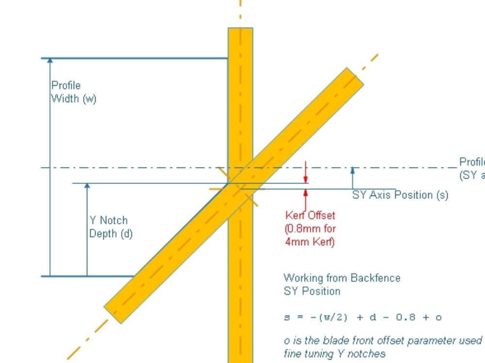
The SY axis datum zero point is the centreline of the profile.
Positive SY Axis direction is from this centreline towards the rear of the machine.
Negative is away from the backfence.
The following diagram shows the Y notch calculations for a profile of width w

Example
For a 34.5mm deep Front Y notch in 70mm profile:
s=-(70/2)+34.5-0.8 = -1.3
For a 38mm deep Front Y notch in 110mm profile:
s=-(110/2)+38-0.8 = -17.8
Limitations
The system is only able to work within the mechanical limitations, which means there are issues with notches that force the sy position out of the +/-20mm range from the centreline, or fall within a "minimum residual" limitation. See this document for details
Draft
 Français
 English
 Deutsch
 Español
 Italiano
 Português