| [version en cours de rédaction] | [version en cours de rédaction] |
| Ligne 5 : | Ligne 5 : | ||
|Categories=Production | |Categories=Production | ||
|Difficulty=Medium | |Difficulty=Medium | ||
| − | |Duration= | + | |Duration=9 |
|Duration-type=hour(s) | |Duration-type=hour(s) | ||
}} | }} | ||
Version du 17 juillet 2023 à 10:29
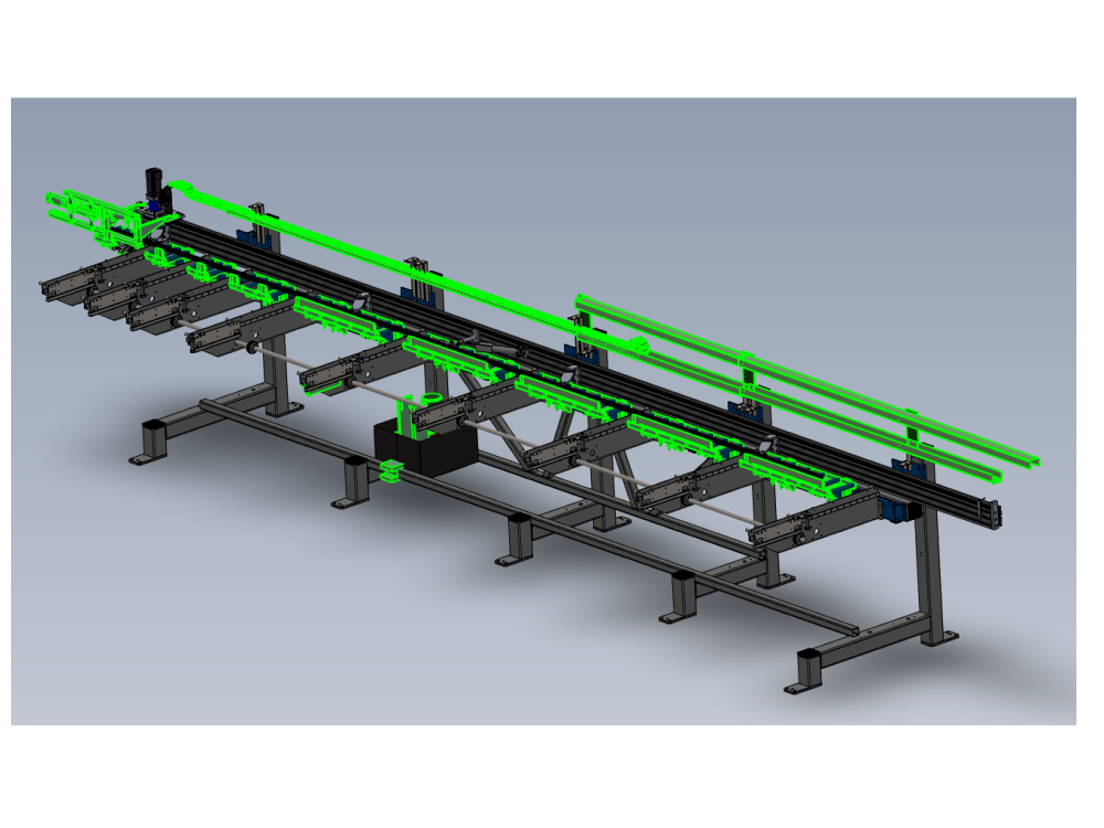
Instructions to mount completed assemblies to main frame

Difficulté
Moyen
Durée
9 heure(s)
Sommaire
- 1 Introduction
- 2 Étape 1 - Unless otherwise stated
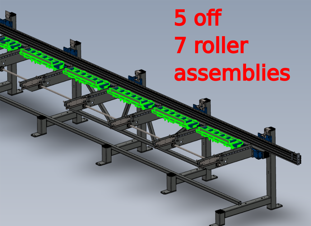
- 3 Étape 2 - Mount pre built R0015063 Bench Assemble Roller Tables
- 4 Étape 3 - Mount pre built R0015011 Bench Assemble Gripper
- 5 Étape 4 - Mount Energy chain angle brackets Lower
- 6 Étape 5 - Mount upper chain angle brackets
- 7 Étape 6 - Mount short upper chain angle brackets
- 8 Étape 7 - Fit lower chain trays
- 9 Étape 8 - Mount upper chain guides
- 10 Étape 9 - Fit Carriage bracket
- 11 Étape 10 - Attach pre built R0015286 energy chain
- 12 Étape 11 - Adjust lower trays to suit energy chain
- 13 Étape 12 - Adjust lower tray height
- 14 Étape 13 - Adjust Top chain guides
- 15 Étape 14 - Quality check
- 16 Étape 15 - Finalise fixings
- 17 Étape 16 - Mount Datum Sensor and bracket
- 18 Étape 17 - Mount R0015096 Bench Assemble Transfer Drive Assembly
- 19 Étape 18 - Add drive chain
- 20 Étape 19 - Now move to section two
- 21 Commentaires
Introduction
Tools Required
Standard Hex key set
Standard spanner set
300 mm rule
1000mm rule
Parts Required
D0008288 Takeup Pad Left (D7339) (Wet/P F Matt) x 1
D0015583 Take Up Beam Joiner x 1
D0015598 Datum Flag: Saw Infeed x 1
D0015717 Energy Chain Angle Bracket Lower x 5
D0015718 Energy Chain Angle Bracket Upper x 2
D0015718B Energy Chain Angle Bracket Double Deck x 3
D0015720 Carriage Bracket x 1
D0015721 Energy Chain Tray Deep Long x 1
D0015723 Energy Chain Tray Shallow x 1
D0015724 Energy Chain Tray Deep x 2
D0015725 Energy Chain Tray Shallow Medium x 1
D0015742 Takeup Pad Right ZX5 x 1
D0015862 Energy Chain Tray Deep Long x 1
E0000336 Sensor: M8; 2mm, PNP N/O, M8 conn x 1
R0015011 Bench Assemble Gripper
R0015063 Bench Assemble Roller Tables
R0015096 Bench Assemble Transfer Drive Assembly
R0015101 Bench assembly take up assembly
R0015286 Bench Assemble X axis components and energy chain
Étape 1 - Unless otherwise stated
Use loctite 243 on all fasteners
Use Loctite 572 on all threaded pneumatic connections
Pen mark all fasteners to show finalised

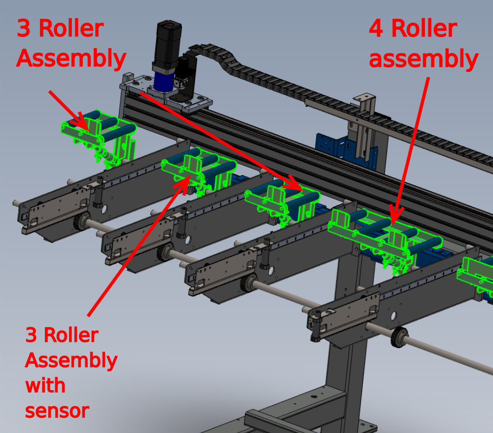
Étape 2 - Mount pre built R0015063 Bench Assemble Roller Tables
Mount roller beds as indicated , using M8 x 30 socket caps and heavy M8 washers.
Do not apply adhesive to fasteners and only apply holding tension to fasteners

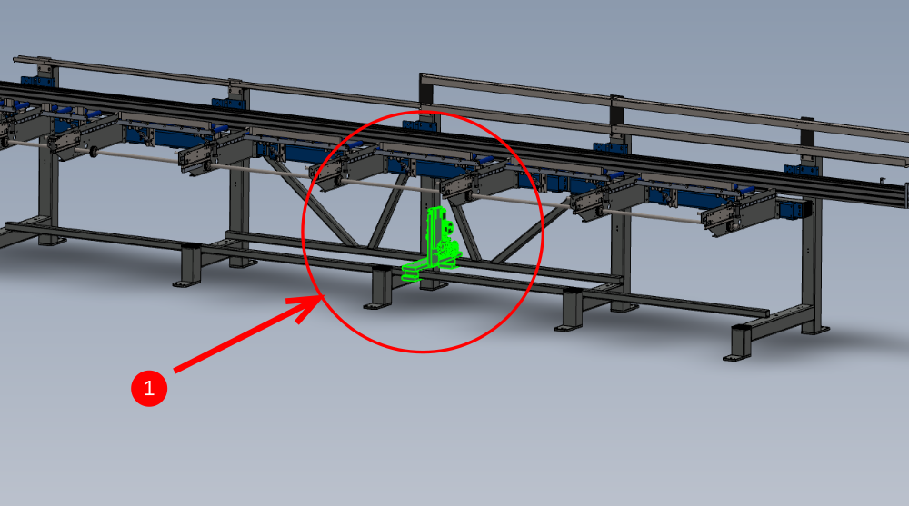
Étape 3 - Mount pre built R0015011 Bench Assemble Gripper
1 Mount Gripper assembly to carriage using 2 off M8 x 35 socket caps 2 off Mi8 x 2 5 socket caps and heavy M8 washers
2 Check and adjust parallel to ensure gripper is true to hepco beam both indicated measurements should be identical


Étape 4 - Mount Energy chain angle brackets Lower
1 Mount 5 off D0015717 Lower mounting angle with 2 off M10 x 25 set bolts and A form washers per bracket . Do not apply adhesive at this point
2 Set height to just clear plastic frame cap and set bracket level

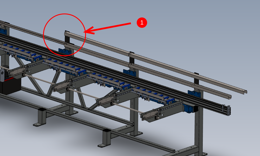
Étape 5 - Mount upper chain angle brackets
1 Mount 3 off D0015718B to positions shown using M6 x 16 socket caps and heavy M6 washers . Do not apply adhesive to fasteners yet
2 Set slot position to be flush with lower bracket
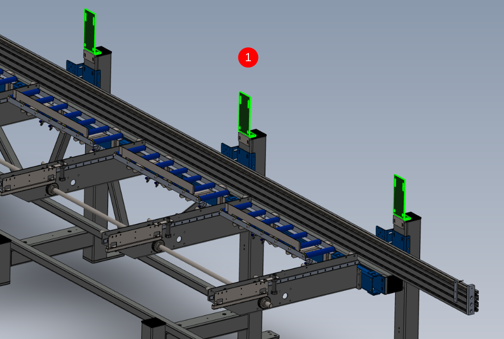

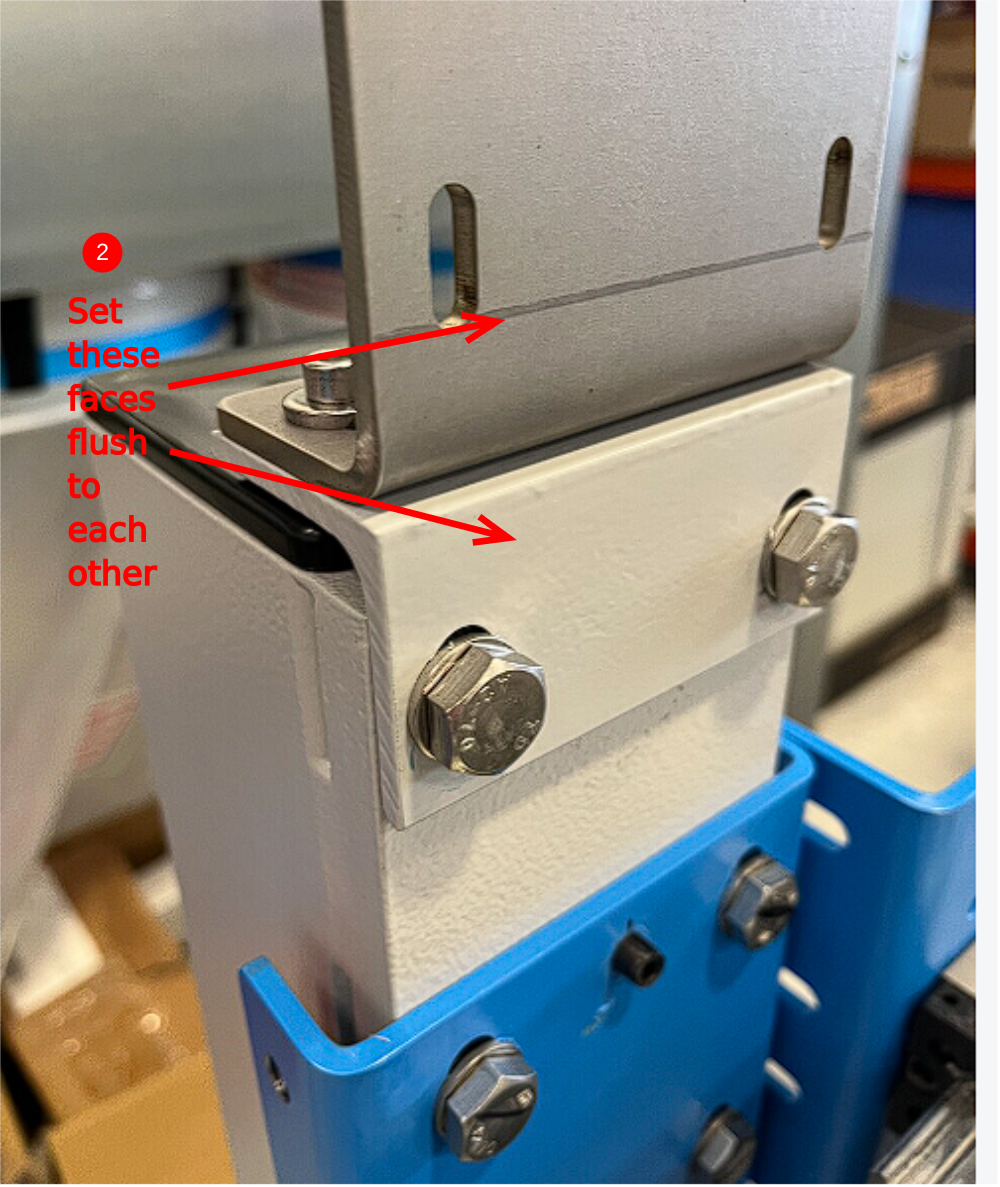
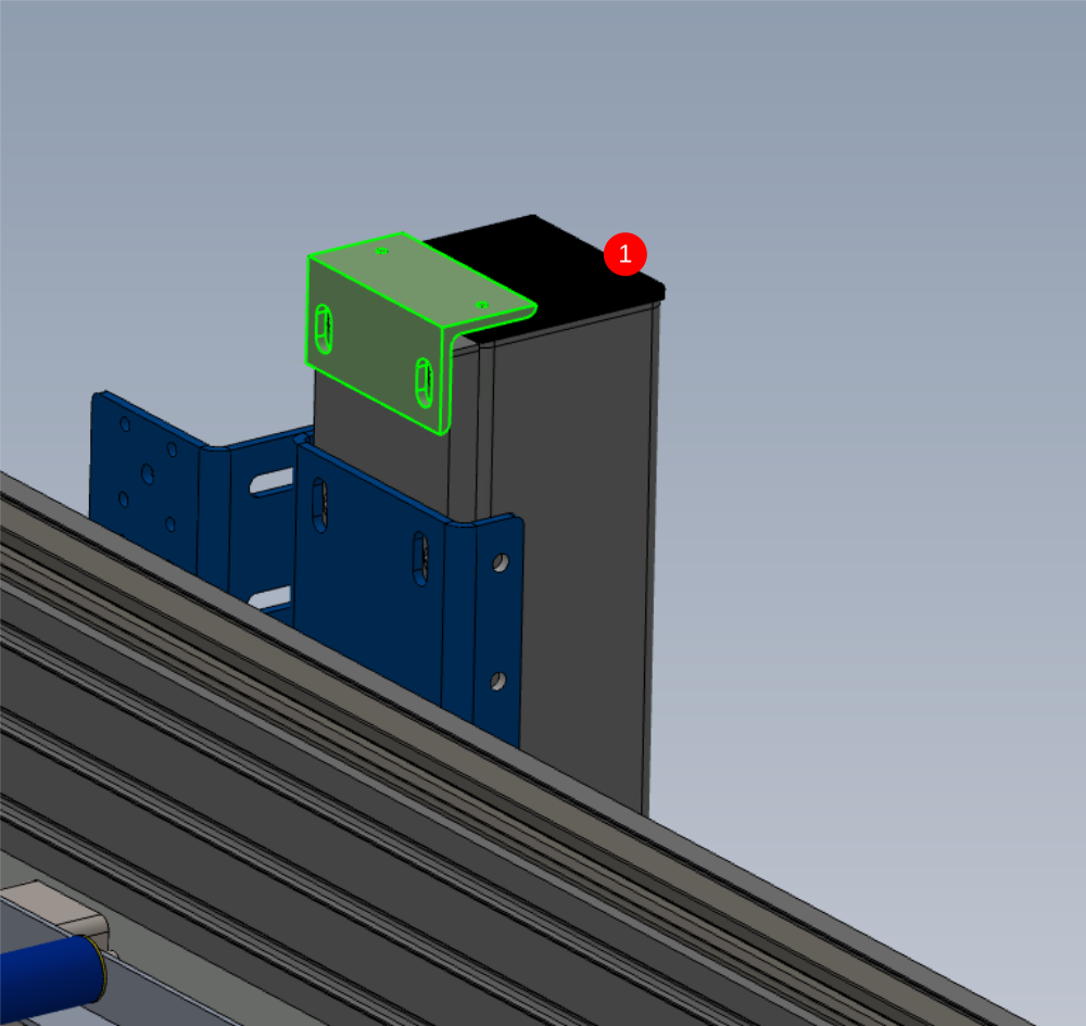
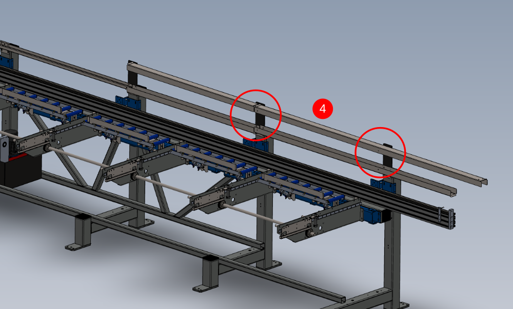
Étape 6 - Mount short upper chain angle brackets
Mount 2 off D0015718 to indicated point using M6 x 16 socket caps and heavy M6 washers . Set faces flush as with previous step
Do not apply adhesive at this point


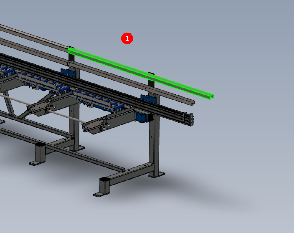
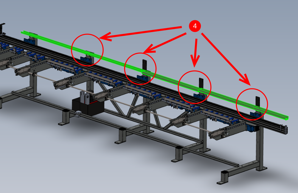
Étape 7 - Fit lower chain trays
Lightly fix these parts, as adjustment will be required later
1 Fit D0015725 at indicated position . Use M5 x 16 button hex bolt, M5 penny washer and M5 nyloc nut .
2 Fit D0015723to indicate point with same fixings as above
3 Fit D0015724 to indicate point with same fixings as above
4 Fit D0015721 to indicate point with same fixings as above
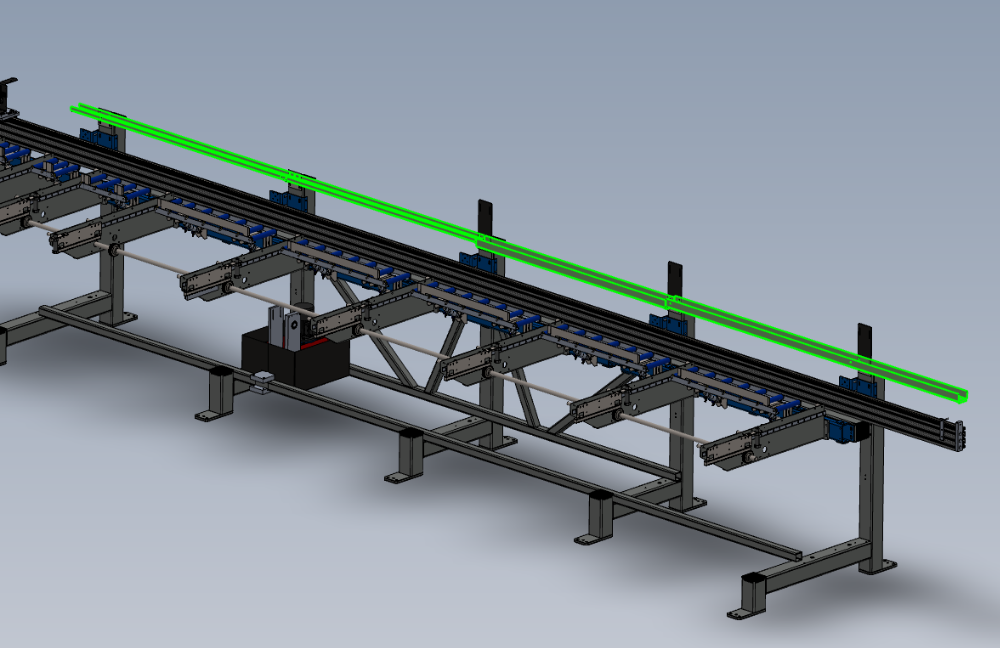


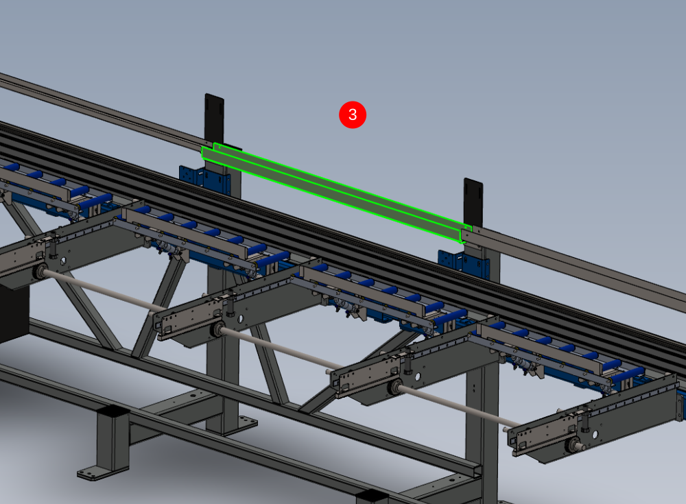

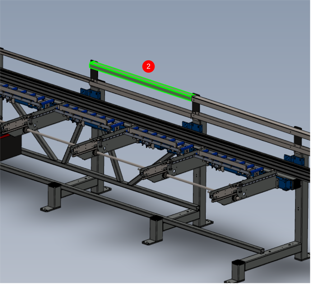
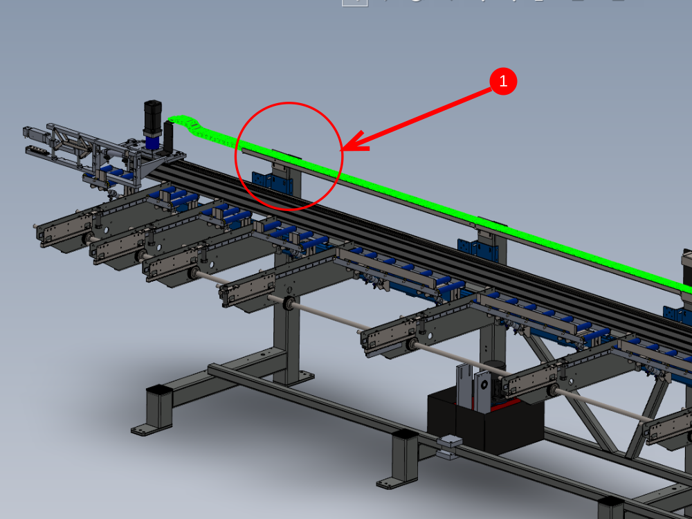
Étape 8 - Mount upper chain guides
Use same method as step 6 to mount indicated upper chain guides 2 off
1 D0015862 upper chain guide
2 D0015724 upper chain guide

Étape 9 - Fit Carriage bracket
Fit D0015720 carriage bracket as shown using M6 x 16 socket caps and A form washers


Étape 10 - Attach pre built R0015286 energy chain
Fit pre built energy chain from assembly R0015286 and attach using M5 x 16 button heads, medium washers and M5 nyloc nuts as shown

Étape 11 - Adjust lower trays to suit energy chain
1 Move gripper with energy chain attached to point indicated
2 Adjust bracket in indicated direction so that energy chain sits central in the tray
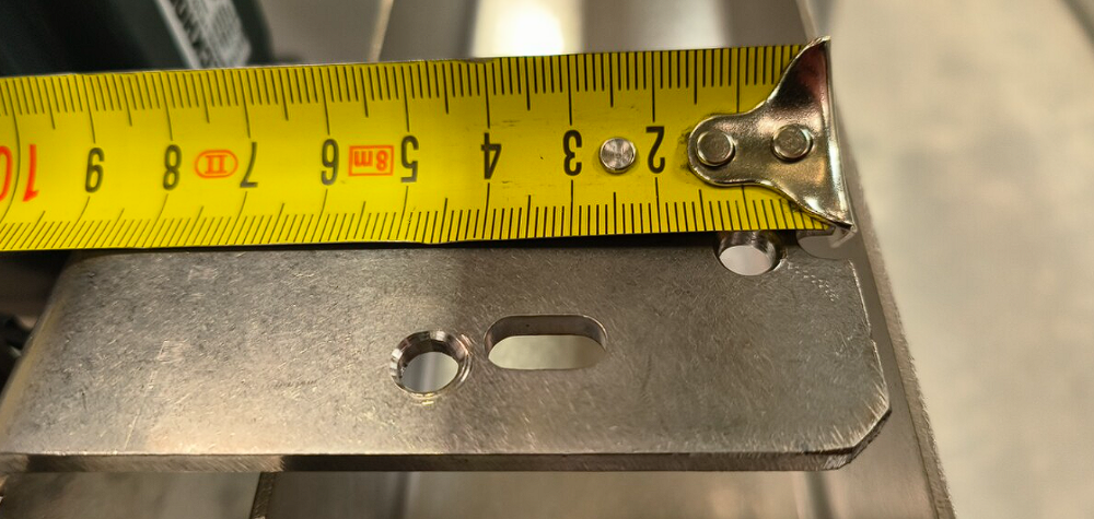
3 Measure indicated distance S
4 Set the next 4 lower tray mounting points to replicate this measurement using the same method of adjustment with the angled bracket


Étape 12 - Adjust lower tray height
Using the first point used to set the brackets , measure the gap indicated and replicate this measurement on the other 4 points . This is adjusted by moving the indicated bracket up or down .


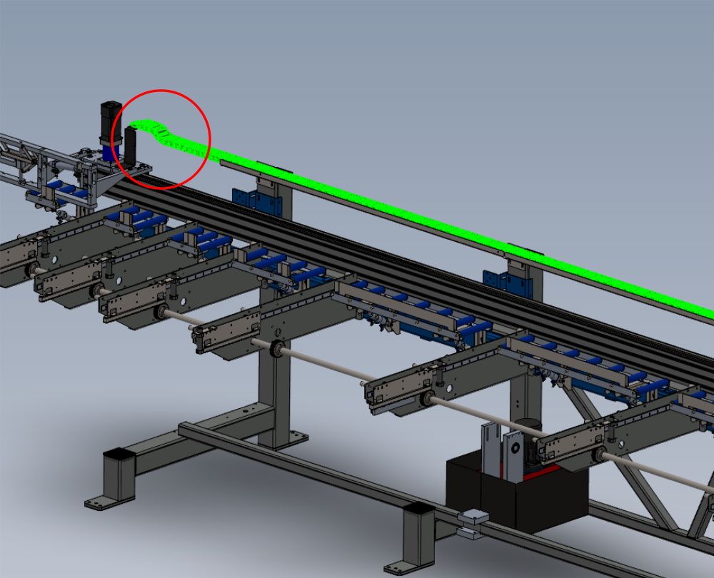
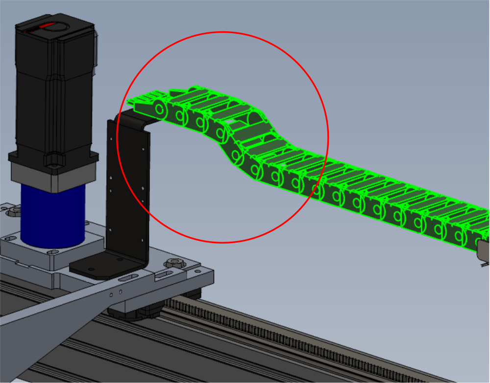
Étape 13 - Adjust Top chain guides
1 Move large radius of energy chain to the indicated point
2 Adjust height of top tray so internal gap is 10mm bigger than the height of the bend of the energy chain
3 Measure indicated gap
4 Set 2 remaining points indicated to step 3 measurement


Étape 14 - Quality check
Move Gripper carriage along the complete length of the hepco beam , and monitor the energy chain .
Check that there is no sideways pressure on the chain from misalignment
Check that no snags occur on fixings when energy chain is travelling

Étape 15 - Finalise fixings
Now aligned , ensure all fixings used to assemble the energy trays and brackets have adhesive apllied and final tension added to fasteners and pen marked
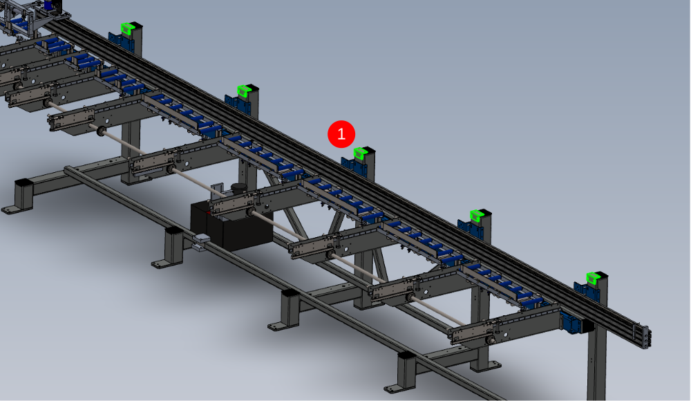
Étape 16 - Mount Datum Sensor and bracket
Mount D0015598 with E0000366 as shown
(measurement required for position please)
Set sensor to carriage face. Gap should be no larger than 1mm. Check gap at all points of travel along carriage face

Étape 17 - Mount R0015096 Bench Assemble Transfer Drive Assembly
1 Position 1 off drive assembly in the positions indicated
2 Use a 1000mm steel rule to align indicated sprocket with drive sprocket on drive shaft indicated


Étape 18 - Add drive chain
1 Fit drive chain to shaft sprocket and motor assembly.
2 Adjust tensioner to apply tension to chain


Étape 19 - Now move to section two
Section two of this dokit must be followed
Found here
Draft
 Français
 English
 Deutsch
 Español
 Italiano
 Português