| [version en cours de rédaction] | [version en cours de rédaction] |
| Ligne 5 : | Ligne 5 : | ||
|Categories=Production | |Categories=Production | ||
|Difficulty=Hard | |Difficulty=Hard | ||
| − | |Duration= | + | |Duration=10 |
|Duration-type=hour(s) | |Duration-type=hour(s) | ||
}} | }} | ||
Version actuelle datée du 3 avril 2024 à 12:32
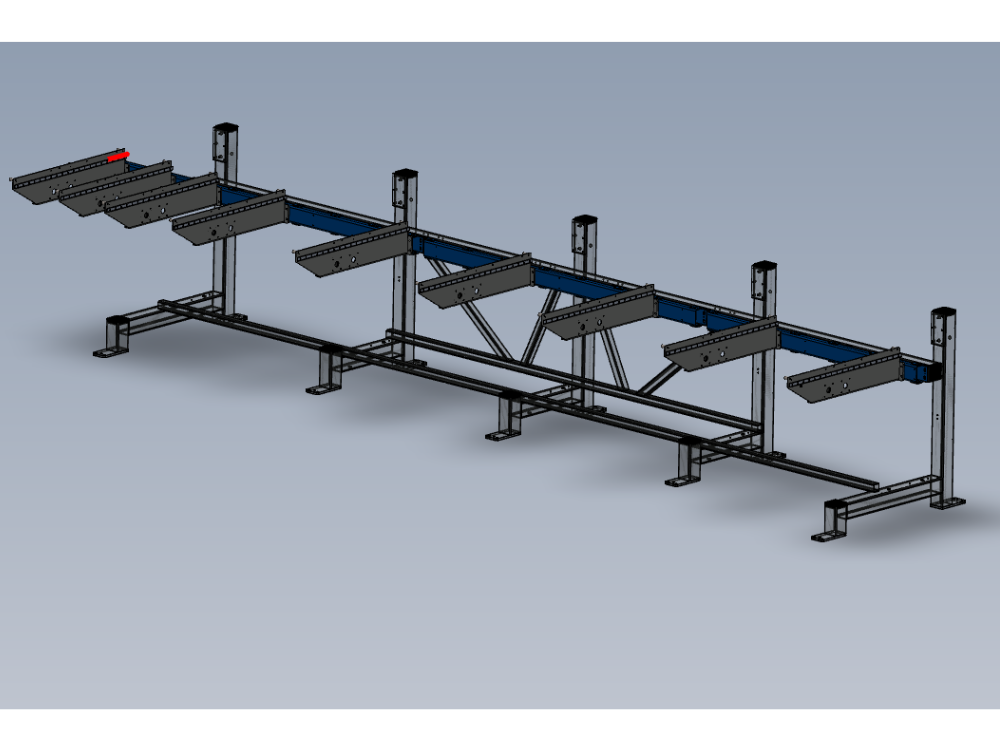
Alignment of loading arm assembly

Difficulté
Difficile
Durée
10 heure(s)
Sommaire
- 1 Introduction
- 2 Étape 1 - Unless otherwise stated
- 3 Étape 2 - Ensure all tape/packaging is removed from components
- 4 Étape 3 - Clean all threads
- 5 Étape 4 - Fitting of Mounting Channel 3
- 6 Étape 5 - Fitting of Mounting channel 2
- 7 Étape 6 - Fitting of mounting channel 1
- 8 Étape 7 - Quality Check Required
- 9 Étape 8 - Finalising Fixings
- 10 Étape 9 - Dowel in Position
- 11 Étape 10 - Mount support channels
- 12 Étape 11 - Mount Support arms to frame
- 13 Étape 12 - Add support brace to Arm
- 14 Étape 13 - Repeat step 8 and 9
- 15 Étape 14 - Assemble and fit Maytec arm support
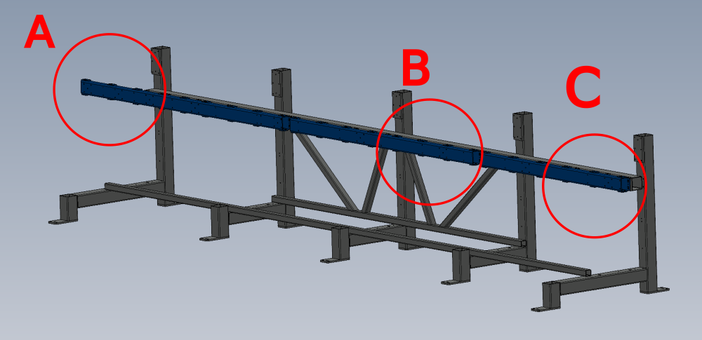
- 16 Étape 15 - Arm alignment
- 17 Étape 16 - Quality Check !
- 18 Étape 17 - Dowel and Fastener finalisation on arms 1 to 7
- 19 Étape 18 - Ensure alignment of end sections
- 20 Étape 19 - Drill final 8mm dowel points
- 21 Étape 20 - Finalise position of arms 8 and 9
- 22 Étape 21 - Set wire line and positions arms 8 and 9
- 23 Étape 22 - Quality Check required
- 24 Étape 23 - Drill and Dowel
- 25 Étape 24 - Alignment complete!
- 26 Commentaires
Introduction
Tools required
Standard Hex key set
Standard HSS drill set
Wire line
Tape Measure
Engineers level 300mm
Pedestal stand
Adjusting jack
Parts Required
D0015035B 1 off
D0015036B 1 off
D0015257 1 off
D0015037B 1 off
D0015038B 1 off
D0015039B 1 off
D0015743 x 1 off
D0015744 x 1 off
M0000516 x 1 off
M0001016 x 1 off
D0015592 x 14 offÉtape 1 - Unless otherwise stated
Use locktite 243 on all fasteners
Use loctite 572 on all threaded pneumatic connection
Pen mark all fasteners to show finalised

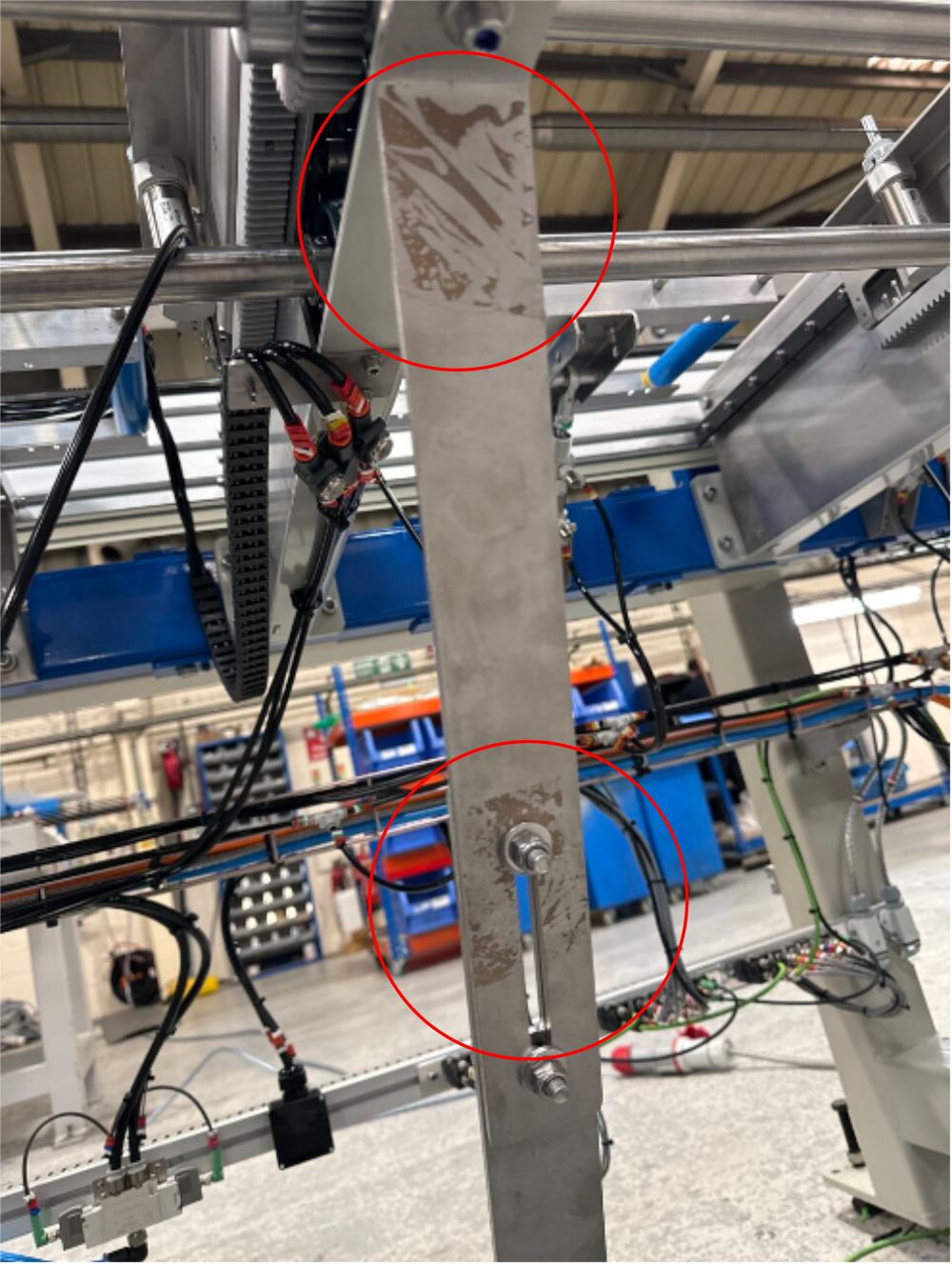
Étape 2 - Ensure all tape/packaging is removed from components
Ensure all tape is removed from components , please see picture of what is NOT acceptable
Étape 3 - Clean all threads
All threads in channels should be tapped to clear any debris present before fitting


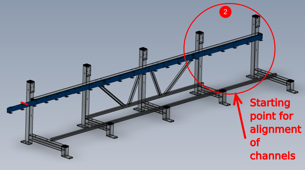
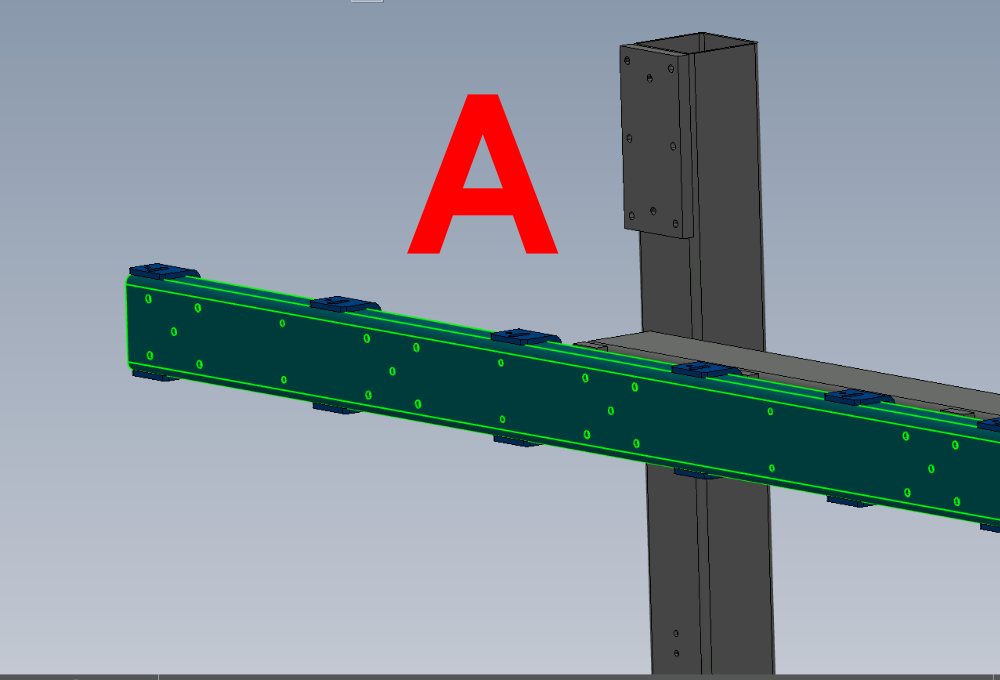
Étape 4 - Fitting of Mounting Channel 3
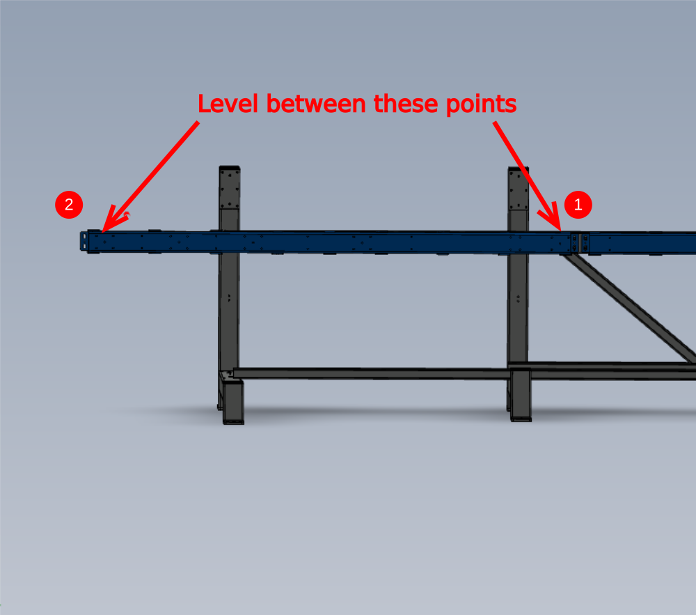
1 Fit mounting channels to frame using M12 x 25 Set bolts and A form washers.
Do not add adhesive to bolts at this stage . Do not tension bolts.
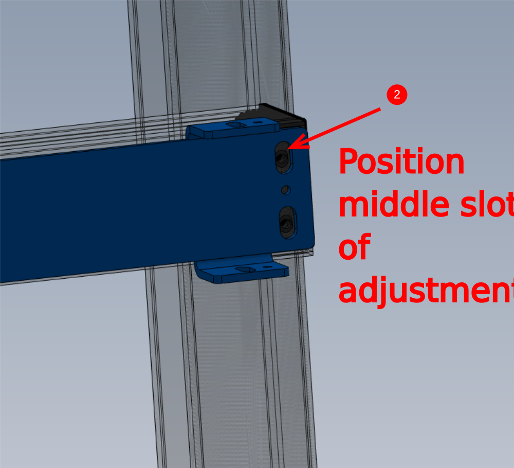
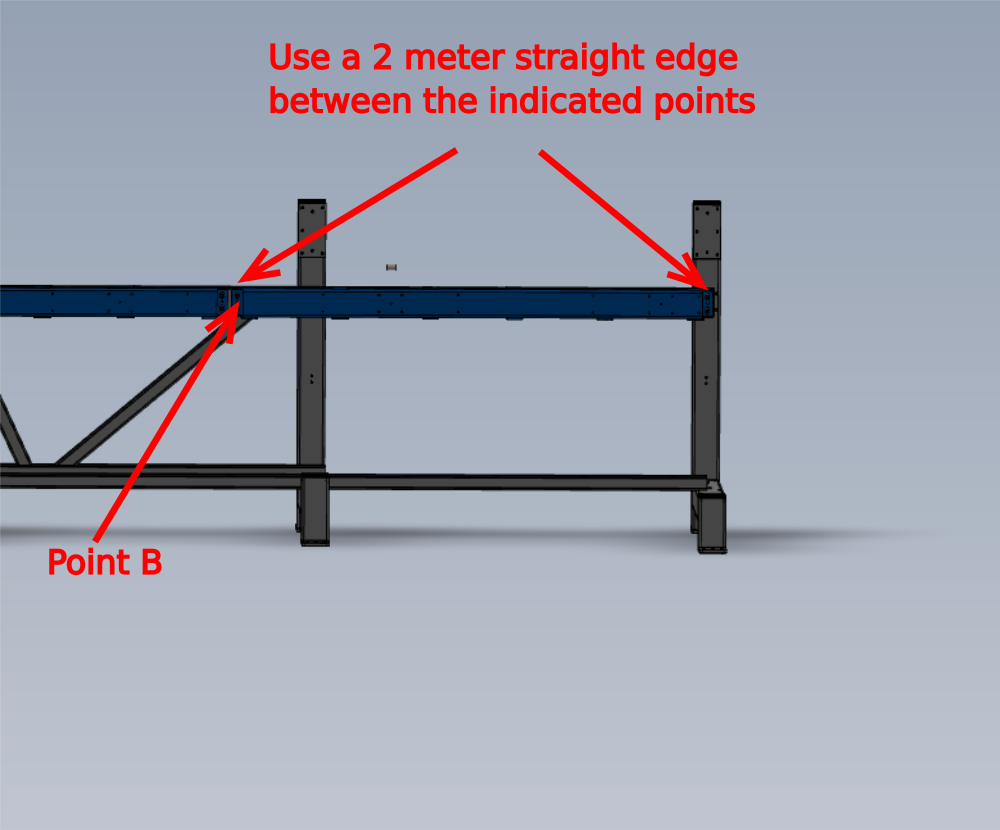
2 Set the first mounting channel to the middle of the adjustment slot at the extreme end of the frame
3 Place 2 meter straight edge between indicated points , and raise or lower point b to bring straight edge level with engineers level
4 Tighten bolts to hold in place


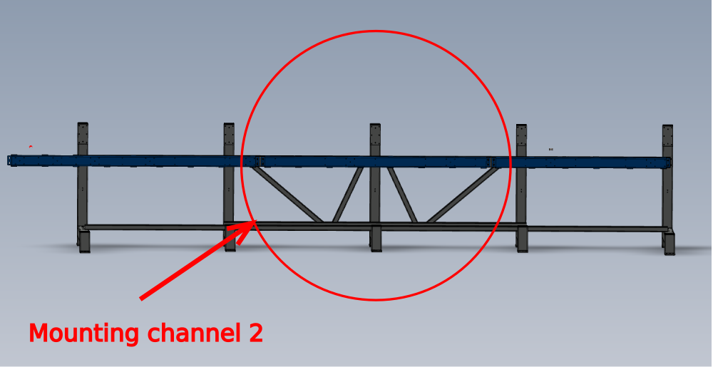
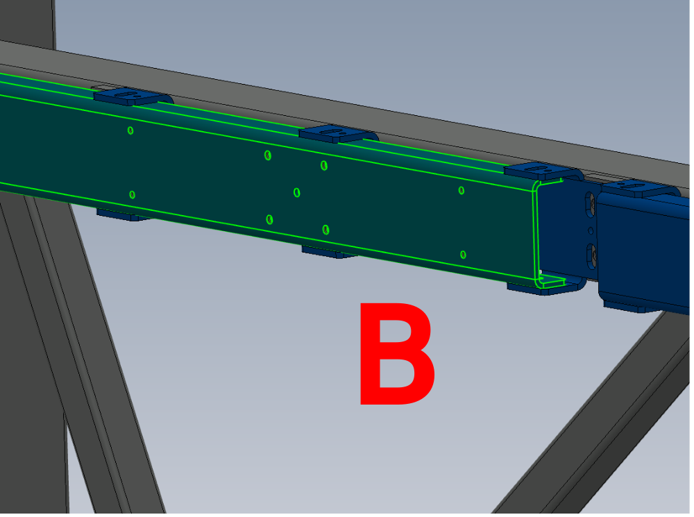
Étape 5 - Fitting of Mounting channel 2
1 Move channel 2 section up or down to copy height of adjacent channel 3. Use the tabs as the reference points
2 Use 2 meter straight edge and level between points indicated
Move channel 2 at the end indicated, to give a level reading
3 Tighten bolts to hold in place
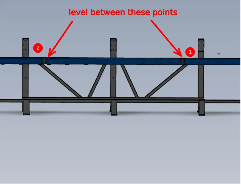
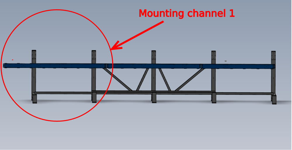
Étape 6 - Fitting of mounting channel 1
1 Move channel 1 section up or down to copy height of adjacent channel 2. Use the tabs as the reference points
2 Use 2 meter straight edge and level between points indicated
Move channel 1 at the end indicated, to give a level reading
3 Tighten bolts to hold in place
Étape 7 - Quality Check Required
Once at this stage with mounting channels being set in position, a quality check is required from a Supervisor.

Étape 8 - Finalising Fixings
1 Remove Set bolt
2 Add adhesive Loctite 243 to bolt.
3 Refit and tighten
4 Mark head with ink to show completion of fixing
5 Repeat for all M12 fixings holding on mounting sections 1,2 and 3

Étape 9 - Dowel in Position
1 Drill 8mm Diameter holes in all roll pin holes situated between previous tightened m12 bolts ( 19 off in total reference detail 1 )
2 Insert 8mm x 24mm spiral pins to 8mm holes
3 Clean drilled areas of swarf and cutting fluid

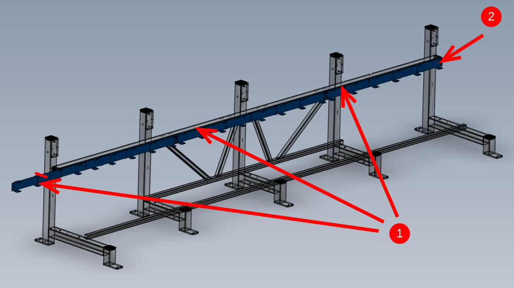
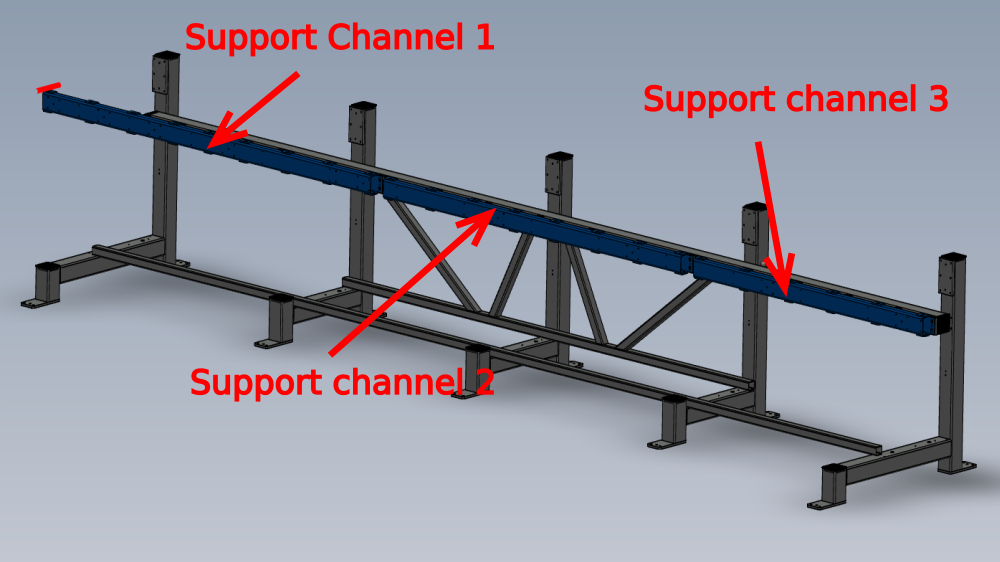
Étape 10 - Mount support channels
Use pictures for orientation
1 Mount support channels to frame using m10 set bolts and m10 A form washers
Do not add adhesive at this point to fixings
2 Set all sections mid slot as per picture
3 Slightly tension bolts to hold in place
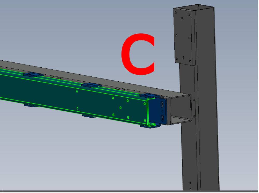

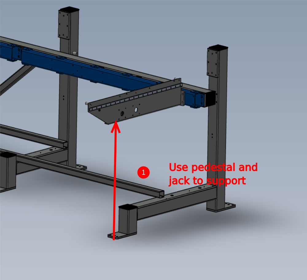
Étape 11 - Mount Support arms to frame
1 Support arm as shown in detail
2 Use 8mm x 24mm spiral spin to locate arm on mounting face
Use m10 x 30 cap heads with no washers to fix arm to mounting face
Use Loctite 243 to fix m10's and loosely secure arm to mounting face
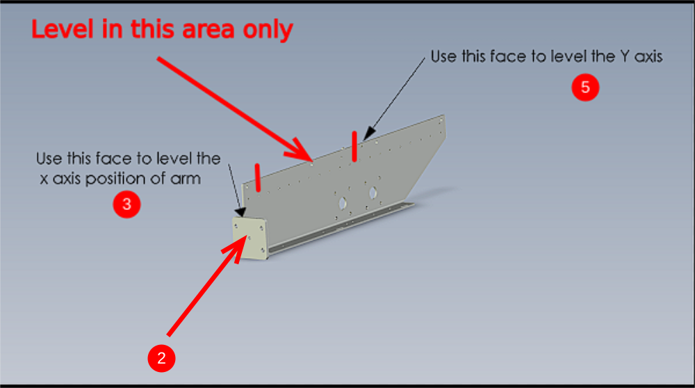
3 Adjust arm for level on X axis by using the indicated face to check level with an engineers level
4 Tighten m10 cap heads to lock x axis position on arm and then ink mark bolts as finished
5 Adjust arm for level on Y axis. Use jack on pedestal to adjust height. Use engineers level on indicated point to check level
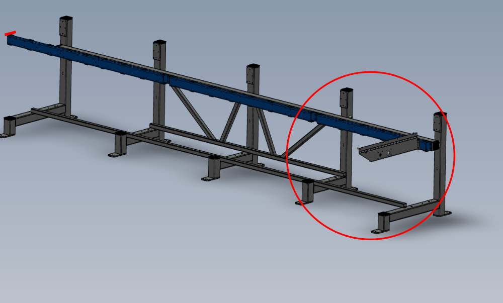
Étape 12 - Add support brace to Arm
1 Add brace to arm as indicted > bottom hole will need drilling into main frame to secure . Drill and tap M6. Position bottom of bracket to dimension shown
2 Repeat Step 8 to mount next arm onto frame.
3 The bottom position of the support brace is determined by the previous arm.
Measure Top pitch and replicate below


Étape 13 - Repeat step 8 and 9
Repeat step 8 and 9 to complete the mounting of the support arms
Leave the pedestal as support under beams 8 and 9
Étape 14 - Assemble and fit Maytec arm support
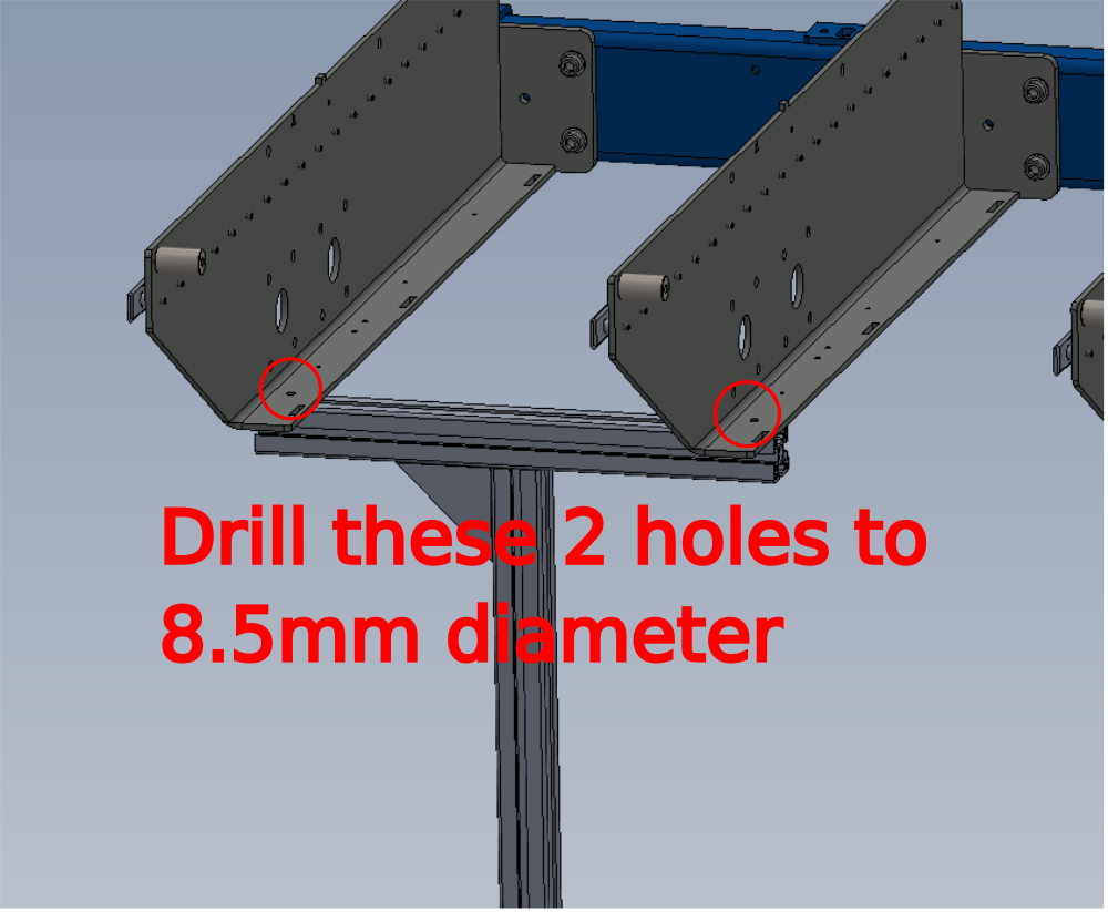
Ensure 2 off fixing holes in support arms are drilled to 8.5mm diameter before fixing support to frame
Please take photos so this step can be updated please
1 Drill arm 8.5mm to suit Maytec section mounting (please supply details So ECR can be generated )
2 Fit Maytec support assembly as shown
Parts used
D0015743 x 1
D0015744 x 1
M0000516 x 1
M0001016 x 1
Adjust assembly to support arm correctly

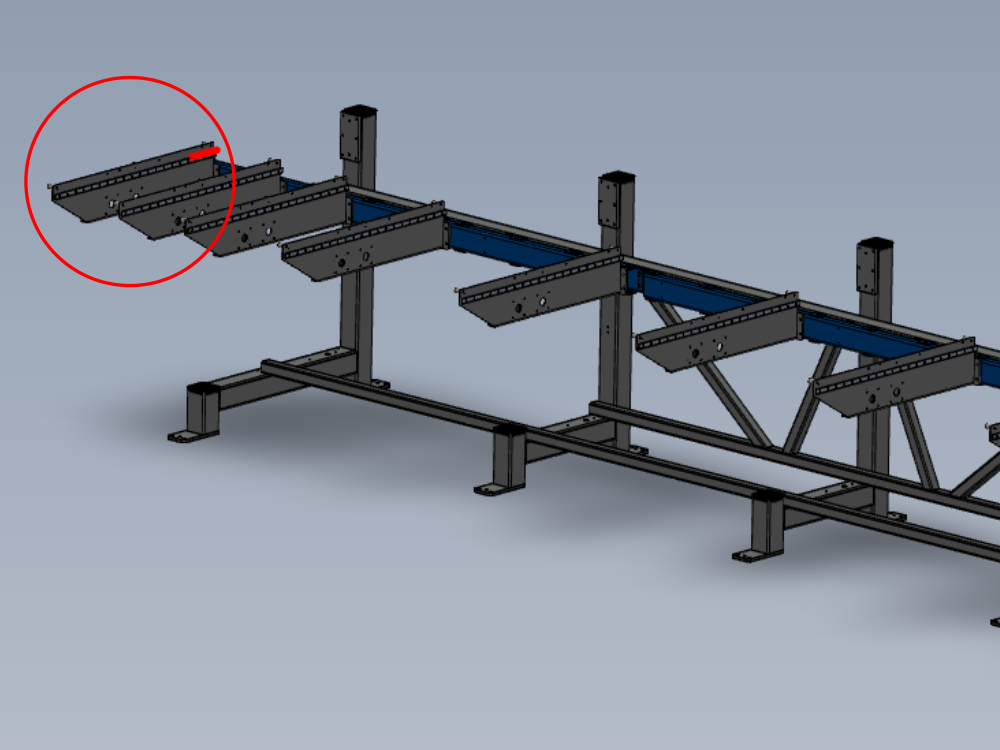
Étape 15 - Arm alignment
use following dokit for alignment
Alignment guide using wire line
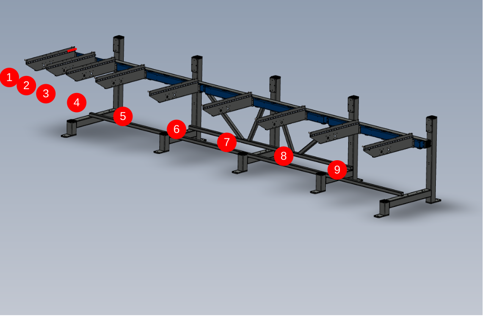
Use support arms 1 and 7 as fixed datum points. The mounting section these are bolted to should be in the middle of their slot adjustment wise.
Set wire line and move indicated arms in directions shown to achieve straightness by wire line
Once alignment has been achieved, Check level of arms on Y axis and adjust if required by using pedestal stand and jack
Recheck alignment if arms have been adjusted on y axis , and correct if necessary


Étape 16 - Quality Check !
Supervisor sign off required for alignment
Étape 17 - Dowel and Fastener finalisation on arms 1 to 7
Secure m10 bolts at positions shown lightly, then drill 8mm diameter to top and bottom faces indicated then add 8mm x 24mm roll pins to drilled holes.
Repeat at all indicated points

Étape 18 - Ensure alignment of end sections
Now the arms are pinned at there local fix points, manipulate the two ends of the blue channel so they are in line with each other
repeat this step at both indicated points

Étape 19 - Drill final 8mm dowel points
Drill Final 8mm diameter holes at the remaining indicated points , top and bottom, and fit 8mm x 25mm roll pins
ow finalise all m10 bolts associated with each dowel , by removing one at a time, adding adhesive and then tightening to final tension. Then mark each bolt as complete with a pen mark.
Repeat this on all bolts next to dowels on the drilled blue section

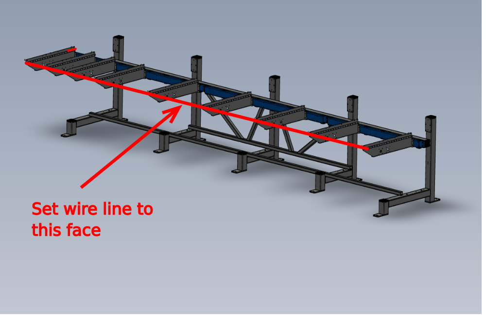
Étape 20 - Finalise position of arms 8 and 9
Now a datum is set, arms 8 and 9 can be finalised
Arms 1 to 7 are used as the datum to set the position of these arms
Étape 21 - Set wire line and positions arms 8 and 9
Set up a wire line onto the indicated face , and use arms 1 to 7 for reference to set the alignment of arms 8 and 9.
Ensure slight gaps on arms 2 to 8 are maintained to ensure the straightness is held along the entire span of arms
Y axis position should be double checked when adjustment is complete for alignment of wire line, and adjusted to suit if required
Étape 22 - Quality Check required
Quality check from supervisor required at this point to assure correct setting of alignment of arms
Étape 23 - Drill and Dowel
Drill indicated remaining 8mm diameter holes next to arms 8 and 9 and fit 8mm roll pins .
Then finalise m10 bolts using the same process as before by removing one by one, adding adhesive and then tightening and marking as complete

Étape 24 - Alignment complete!
Draft
 Français
 English
 Deutsch
 Español
 Italiano
 Português