Alignment of loading arm assembly

Difficulté
Moyen
Durée
8 heure(s)
Sommaire
- 1 Introduction
- 2 Étape 1 - Fitting of Mounting Channel 3
- 3 Étape 2 - Fitting of Mounting channel 2
- 4 Étape 3 - Fitting of mounting channel 1
- 5 Étape 4 - Quality Check Required
- 6 Étape 5 - Finalising Fixings
- 7 Étape 6 - Dowel in Position
- 8 Étape 7 - Mount support channels
- 9 Étape 8 - Mount Support arms to frame
- 10 Étape 9 - Add support brace to Arm
- 11 Étape 10 - Repeat step 8 and 9
- 12 Étape 11 - Arm alignment
- 13 Étape 12 - Quality Check !
- 14 Étape 13 - Dowel and Fastener finalisation on arms 1 to 7
- 15 Commentaires
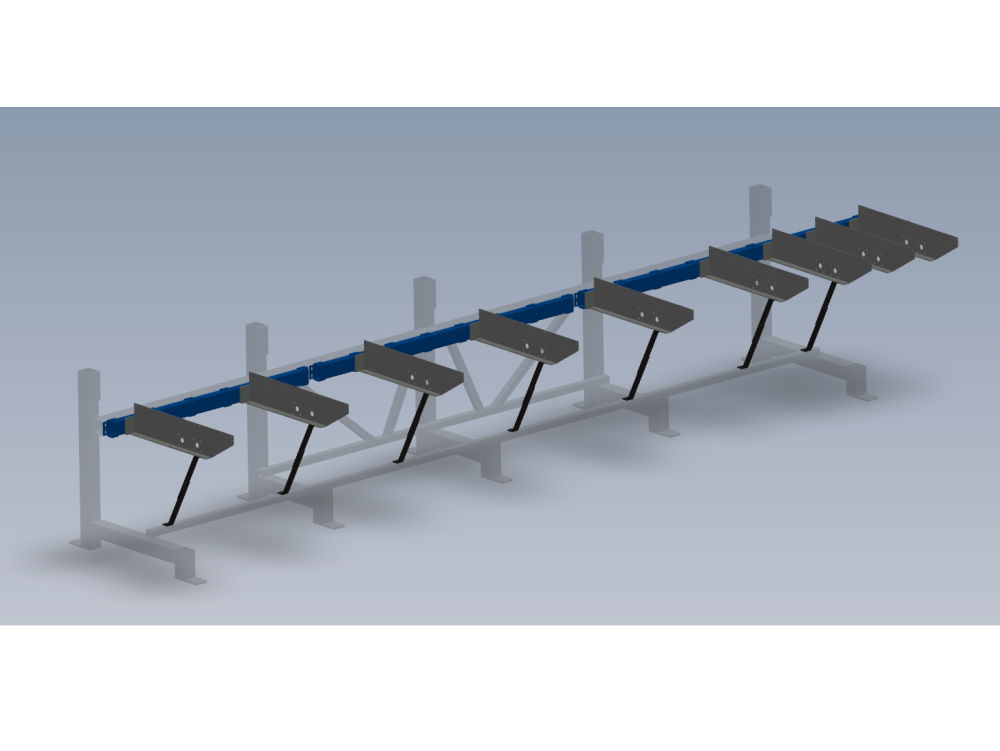
Introduction
Procedure for correct alignment of mounting sections to main frame, and relative setting of load arms
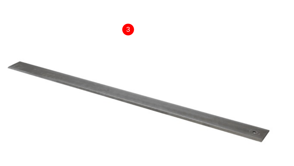
Parts required
D0015038B 1 off
D0015039B 1 off
D0015257 1 off
D0015037B 1 off
D0015038B 1 off
D0015039B 1 off
D0015552 9 off
D0015592 18 off
Étape 1 - Fitting of Mounting Channel 3
1 Fit mounting channels to frame using m12 Set bolts and A form washers.Do not add adhesive to bolts at this stage . Do not tension bolts.
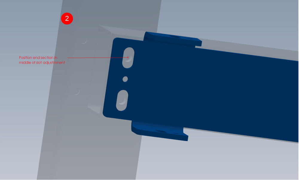
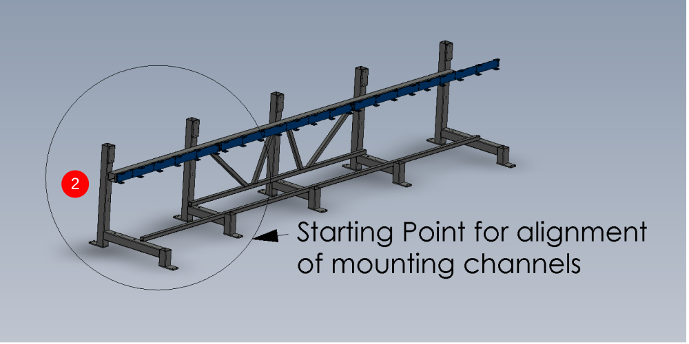
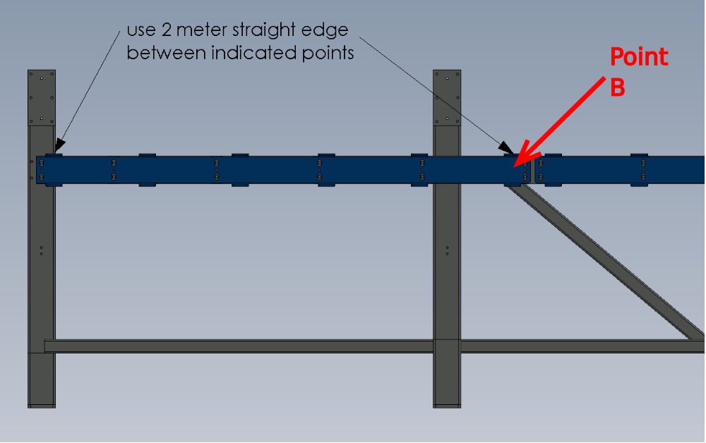
2 Set the first mounting channel to the middle of the adjustment slot at the extreme end of the frame
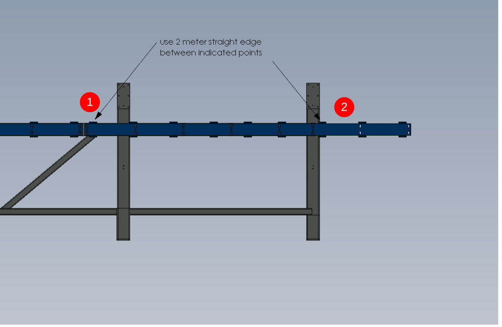
3 Place 2 meter straight edge between indicated points , and raise or lower point b to bring straight edge level with engineers level
4 Tighten bolts to hold in place

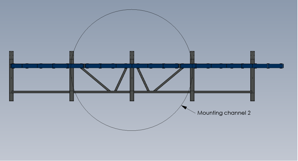
Étape 2 - Fitting of Mounting channel 2
1 Move channel 2 section up or down to copy height of adjacent channel 3. Use the tabs as the reference points
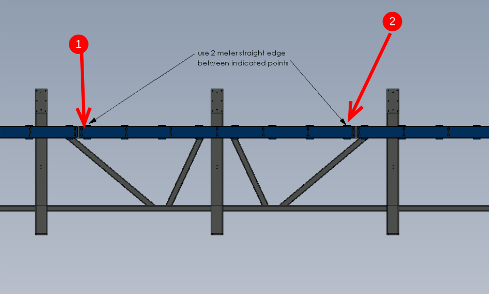
2 Use 2 meter straight edge and level between points indicated
Move channel 2 at the end indicated, to give a level reading
3 Tighten bolts to hold in place
Étape 3 - Fitting of mounting channel 1
1 Move channel 1 section up or down to copy height of adjacent channel 2. Use the tabs as the reference points
2 Use 2 meter straight edge and level between points indicated
Move channel 1 at the end indicated, to give a level reading
3 Tighten bolts to hold in place

Étape 4 - Quality Check Required
Once at this stage with mounting channels being set in position, a quality check is required from a Supervisor.

Étape 5 - Finalising Fixings
1 Remove Set bolt
2 Add adhesive Loctite 243 to bolt.
3 Refit and tighten
4 Mark head with ink to show completion of fixing
5 Repeat for all M12 fixings holding on mounting sections 1,2 and 3

Étape 6 - Dowel in Position
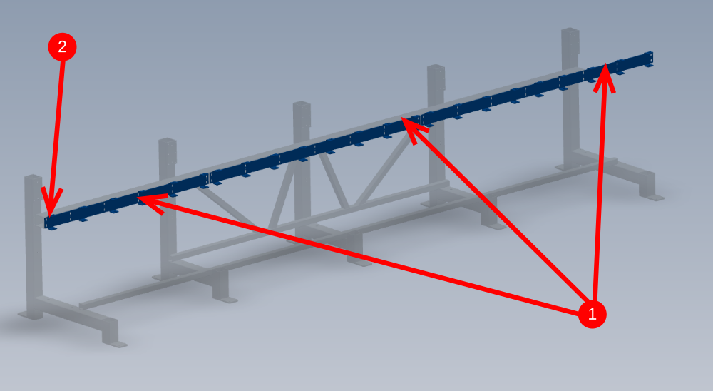
1 Drill 8mm Diameter holes in all roll pin holes situated between previous tightened m12 bolts ( 19 off in total reference detail 1 )
2 Insert 8mm x 24mm spiral pins to 8mm holes
3 Clean drilled areas of swarf and cutting fluid

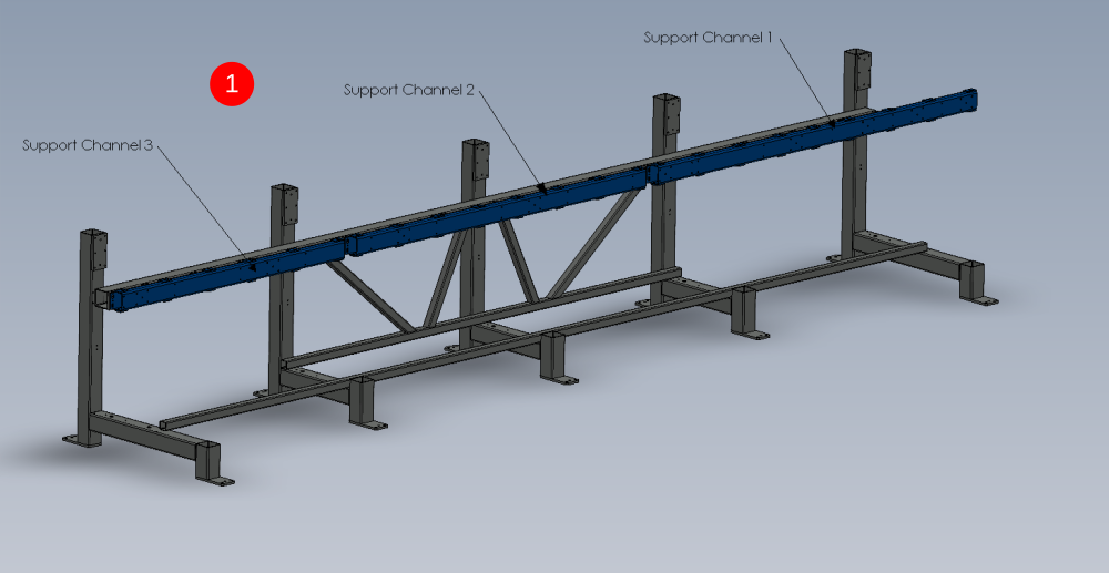
Étape 7 - Mount support channels
1 Mount support channels to frame using m10 set bolts and m10 A form washers
Do not add adhesive at this point to fixings
2 Set all sections mid slot as per picture
3 Slightly tension bolts to hold in place
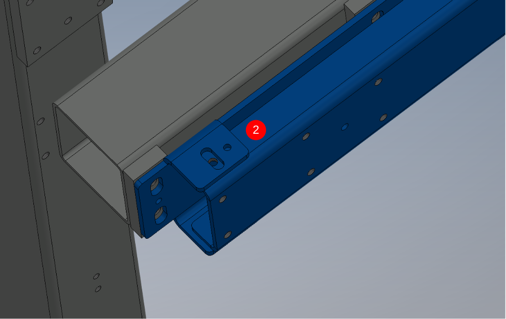
Étape 8 - Mount Support arms to frame
1 Support arm as shown in detail
2 Use 8mm x 25mm spiral spin to locate arm on mounting face
Use m10 cap heads with no washers to fix arm to mounting face
Use Loctite 243 to fix m10's and loosely secure arm to mounting face
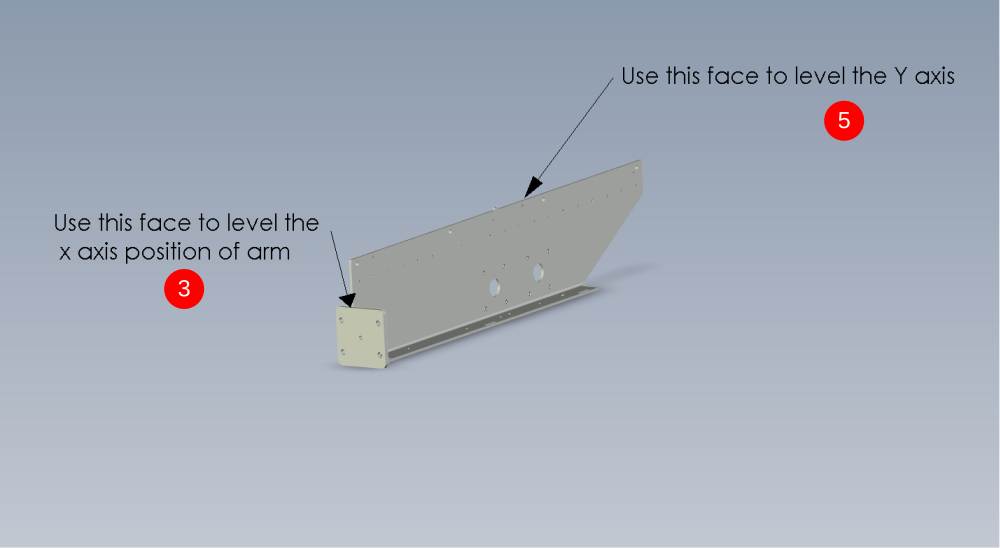
3 Adjust arm for level on X axis by using the indicated face to check level with an engineers level
4 Tighten m10 cap heads to lock x axis position on arm and then ink mark bolts as finished
5 Adjust arm for level on Y axis. Use jack on pedestal to adjust height. Use engineers level on indicated point to check level


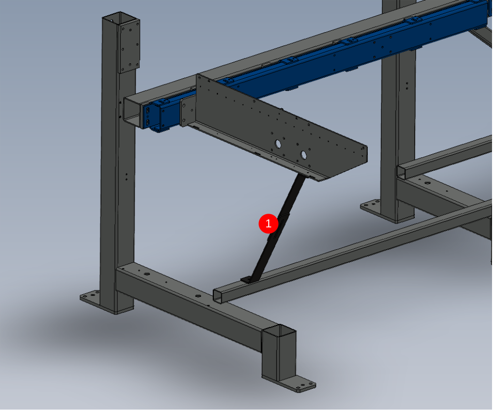
Étape 9 - Add support brace to Arm
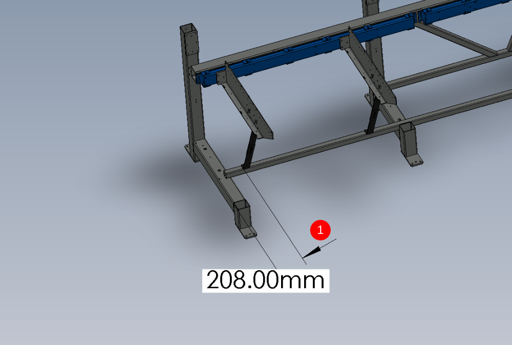
1 Add brace to arm as indicted > bottom hole will need drilling into main frame to secure . Drill and tap M6. Position bottom of bracket to dimension shown
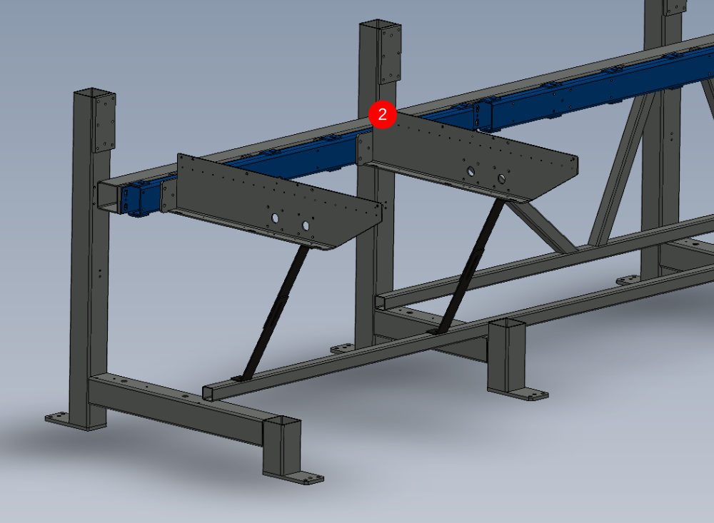
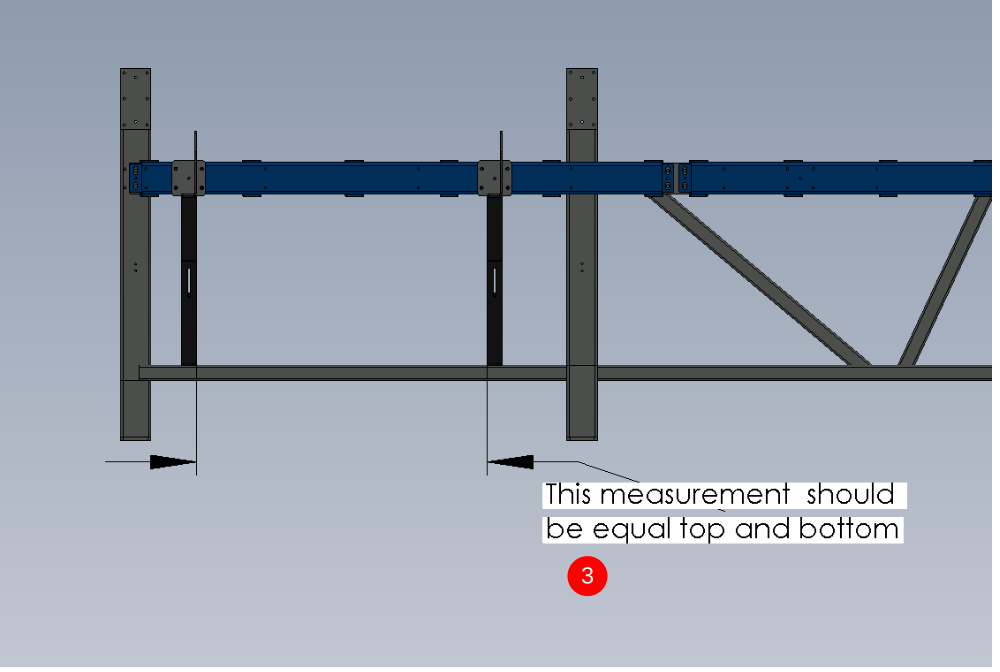
2 Repeat Step 8 to mount next arm onto frame.
3 The bottom position of the support brace is determined by the previous arm.
Measure Top pitch and replicate below
Étape 10 - Repeat step 8 and 9
Repeat step 8 and 9 to complete the mounting of the support arms
Leave the pedestal as support under beams 8 and 9
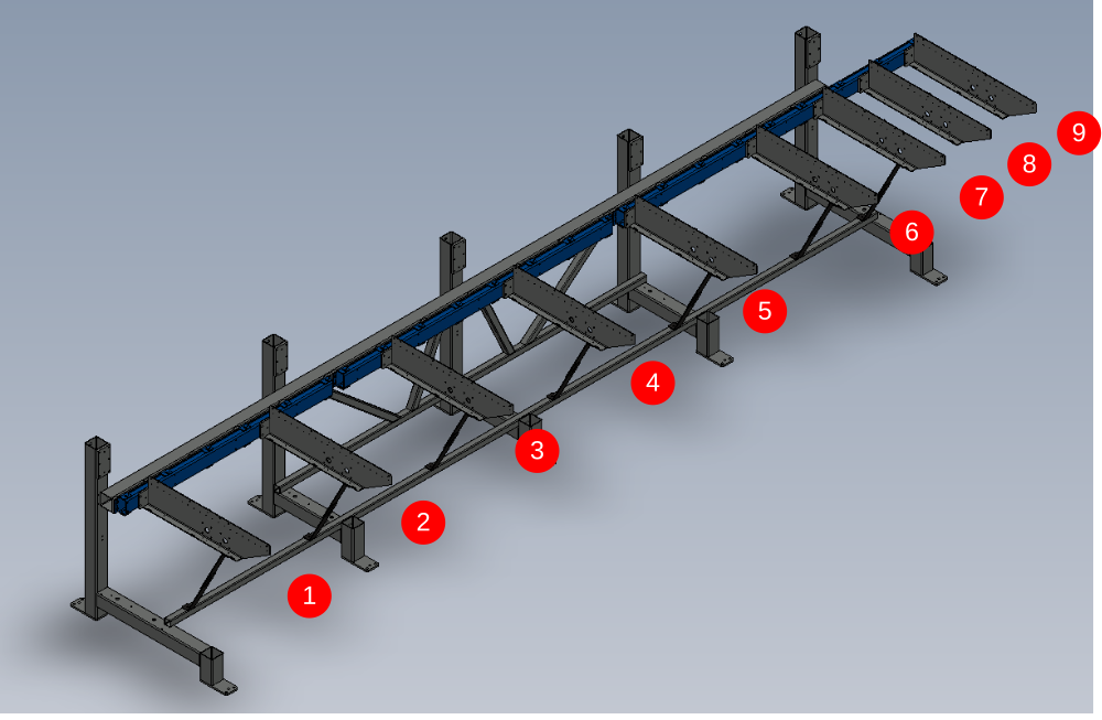
Étape 11 - Arm alignment
use following dokit for alignment
Alignment guide using wire line
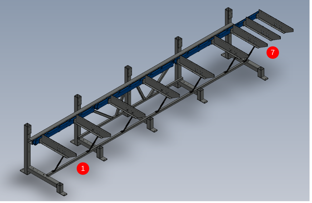
Use support arms 1 and 7 as fixed datum points. The mounting section these are bolted to should be in the middle of their slot adjustment wise.
Set wire line and move indicated arms in directions shown to achieve straightness by wire line
Once alignment has been achieved, Check level of arms on Y axis and adjust if required by using pedestal stand and jack
Recheck alignment if arms have been adjusted on y axis , and correct if necessary

Étape 12 - Quality Check !
Supervisor sign off required for alignment
Étape 13 - Dowel and Fastener finalisation on arms 1 to 7

Draft
 Français
 English
 Deutsch
 Español
 Italiano
 Português