Details for correct setting of roller bed assemblies

Difficulté
Difficile
Durée
8 heure(s)
Sommaire
- 1 Introduction
- 2 Étape 1 - Unless otherwise stated
- 3 Étape 2 - Air Supply
- 4 Étape 3 - Level roller beds
- 5 Étape 4 - Cylinder adjustment
- 6 Étape 5 - Check fasteners
- 7 Étape 6 - Position Engineers level
- 8 Étape 7 - Adjust cylinder stroke
- 9 Étape 8 - Double cylinder roller beds
- 10 Étape 9 - Repeat
- 11 Étape 10 - Quality check on roller beds
- 12 Étape 11 - Height setting
- 13 Étape 12 - Please Note!!
- 14 Étape 13 - Position gripper
- 15 Étape 14 - Gap Setting
- 16 Étape 15 - Double cylinder assemblies
- 17 Étape 16 - Finalise fixings
- 18 Étape 17 - Repeat above steps
- 19 Étape 18 - Check transitions
- 20 Commentaires
Introduction
Tools Required
Standard hex key set
Standard spanner set
Engineers level
2mm shim spacer
2 meter straight edge
Parts Required
Étape 1 - Unless otherwise stated
Use Loctite 243 on all fasteners
Use Loctite 572 on all threaded pneumatic connection
Pen mark all fasteners to show finalised

Étape 2 - Air Supply
The following steps require air supply to be active on the home line of the roller beds. Connect air to feed pipe from manifold bank to lift roller assemblies to home position

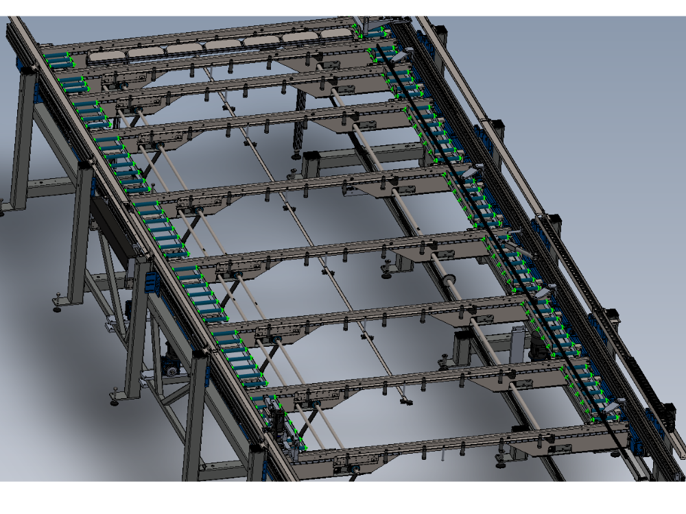
Étape 3 - Level roller beds
It is vital roller beds are levelled and positioned correctly
The following steps should be repeated for each and every roller bed assembly

Étape 4 - Cylinder adjustment
Each cylinder assembly will require adjusting to level roller bed correctly

Étape 5 - Check fasteners
Check fasteners holding roller assembly to frame are tensioned correctly. Not adhesive is required at this stage

Étape 6 - Position Engineers level
Engineers level should be positioned directly above cylinder assembly

Étape 7 - Adjust cylinder stroke
Wind back cylinder lock nut and apply 1 drop of Loctite 243 to exposed cylinder thread
Adjust cylinder stroke to bring engineers level to level position
Lock Locking nut in position ,Ensure that 2 spanners are used to hold spherical bearing and cylinder lock nut when tensioning
Ensure level is not affected on tensioning. If so, re adjust to correct
Apply final tension to cylinder lock nuts and mark as finalised

Étape 8 - Double cylinder roller beds
If a double cylinder roller bed is levelled , it is vital to check the first cylinder again after setting second cylinder level position
Étape 9 - Repeat
Repeat levelling process for all roller beds on module C and E

Étape 10 - Quality check on roller beds
Use a 2 meter straight edge to roll across the top face of all the roller beds when in the up position.
Transition should be smooth and bump free from each roller bed to the next
Check in both directions of travel

Étape 11 - Height setting
It is vital the roller beds are set at the correct height in relationship to the gripper assembly
The following steps should be used to correctly set roller bed heights
Étape 12 - Please Note!!
When adjusting height of roller bed assemblies, do not use impact from hammer to adjust . This leads to damage of the small top hat bush within the assembly . adjust height position with fasteners slack , so no force is applied to these bushes
Étape 13 - Position gripper
Gripper should be positioned directly above cylinder to be adjusted
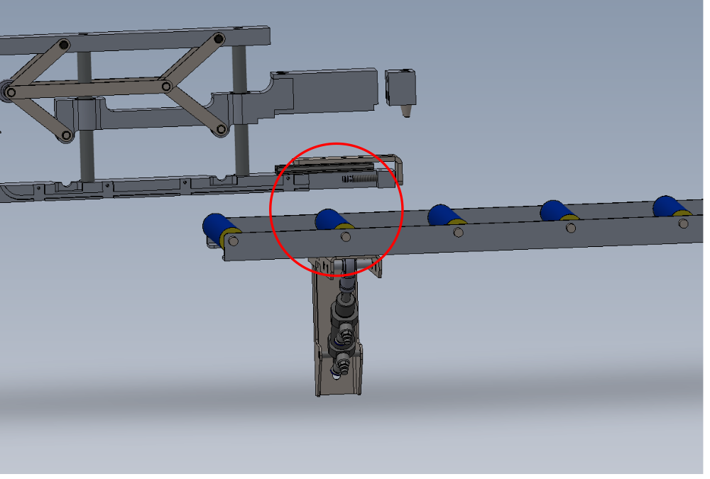
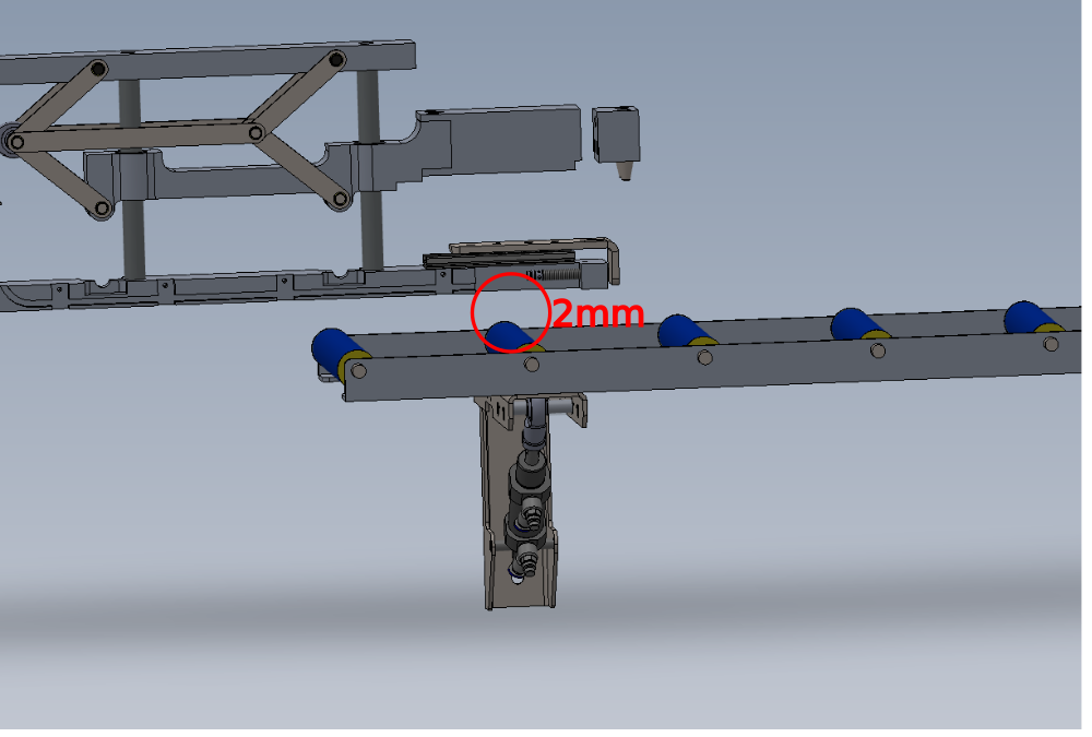
Étape 14 - Gap Setting
Gap requires setting to 2mm between bottom of gripper and top of roller
Use a 2mm shim to set this distance
To adjust roller bed height, slacken bracket fixings and move bracket on slot

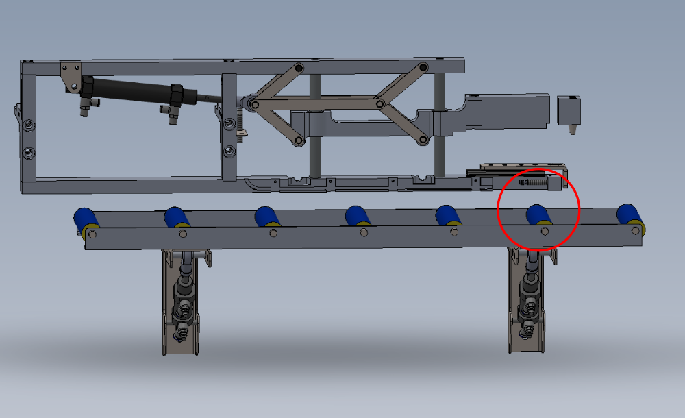
Étape 15 - Double cylinder assemblies
Double cylinder assemblies will need additional setting.
Adjust first cylinder position height
Move gripper to second cylinder
Adjust second cylinder position
Move gripper back to first cylinder and check position hasn't altered
Étape 16 - Finalise fixings
Once correct height has been set, adhesive will need individually applying to each fastener
2 off M8 per bracket require finalising

Étape 17 - Repeat above steps
Repeat above steps to set all roller beds on module C and E using the gripper as the datum for each roller bed

Étape 18 - Check transitions
Use a 2 meter straight edge to 'Roll ' along the levelled and set roller bed assemblies
Transition from one roller bed assembly to the next should be smooth with with no jump or drop onto neighbouring roller beds
If discrepancies are found, double check height and levelling, and if correct report to supervisor
Draft
 Français
 English
 Deutsch
 Español
 Italiano
 Português