Details to install pneumatic loom

Difficulté
Difficile
Durée
8 heure(s)
Sommaire
- 1 Introduction
- 2 Étape 1 - Unless otherwise stated
- 3 Étape 2 - Valve bank identification
- 4 Étape 3 - Y80 Infeed top clamp
- 5 Étape 4 - Y82 Outfeed top clamp
- 6 Étape 5 - Y91 Eject
- 7 Étape 6 - Y202 side clamp
- 8 Étape 7 - Y204 Clamp position
- 9 Étape 8 - Y206 centralise
- 10 Étape 9 - Y207 saw cut
- 11 Étape 10 - Y210 Z support infeed
- 12 Étape 11 - Y213 Saw blowers
- 13 Étape 12 - Y214 Z Turret infeed
- 14 Étape 13 - Y215 Z Turret outfeed
- 15 Étape 14 - Y224 Outfeed Z block
- 16 Commentaires
Introduction
Tools Required
Pipe cutters
Pipe identification markers
Flush cutters
Parts Required
P0000046 Fitting: 'Y' Adaptor 6mm x 6
P0000047 Bulkhead Elbow 6mm x 1
P0000159 Fitting: Stem Blanking Plug 6mm x 2
P0000160 Fitting: Flow Controller In Line 6mm x 2
P0000551 6mm inline Quick Exhaust Fitting x 3
P0001030 Fitting: SMC 6mm Equal Tee x 1
P0001106 Plug in reducer 12-8mm x 1
P0001107 Fitting 12mm equal tee x 1
P0001166 12mm tube to tube elbow x 1
Étape 1 - Unless otherwise stated
All bolts to have Loctite 243 adhesive applied unless otherwise stated
All Threaded Pneumatic connections to have Loctite 570 applied
All bolts to be pen marked once adhesive applied and correct tension added

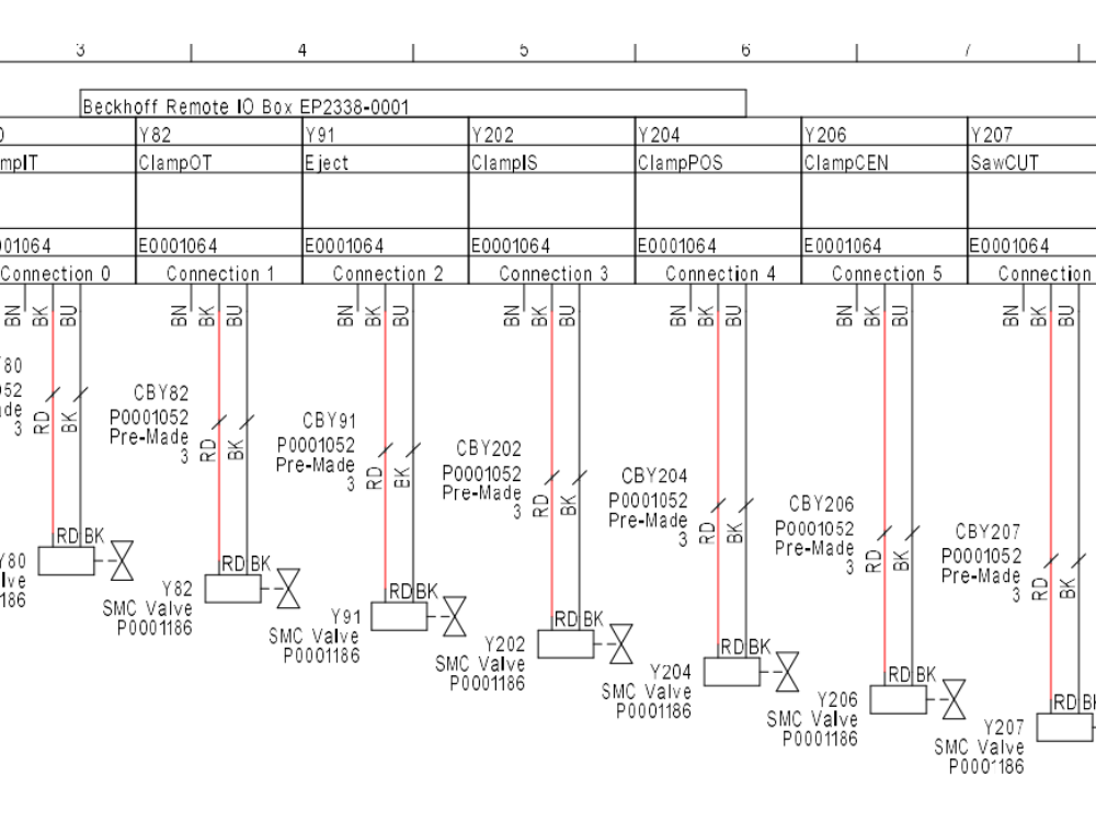
Étape 2 - Valve bank identification
2 row is home position
4 row is active

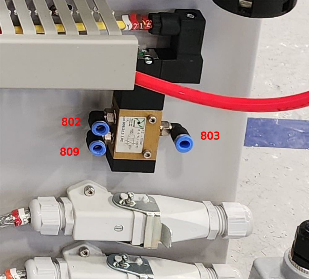
Étape 3 - Y80 Infeed top clamp
801 valve bank home to cylinder nose
809 valve bank active Y to feed Y80 regulator in and port indicated on picture
802 Regulator out to feed port indicated on picture
803 to feed cylinder rear port and valve port indicated . P0000551 to be fitted to this line next to cylinder

Étape 4 - Y82 Outfeed top clamp
821 from Valve bank home to cylinder nose
829 from valve bank active to cylinder rear
Étape 5 - Y91 Eject
911 from valve bank home to cylinder nose
919 from valve bank active to cylinder rear
Étape 6 - Y202 side clamp
2021 from valve bank home to cylinder rear
2029 from valve bank active to regulator in
2022 from regulator out to cylinder nose.
Add P0000551 to 2022 close to cylinder
Étape 7 - Y204 Clamp position
2041 from valve bank home to in on p0000160 flow regulator then out, Y connection then feeds to nose of both cylinders
2049 from valve bank active to in on p0000160 flow regulator then out, Y connection then feeds to rear of both cylinders
Étape 8 - Y206 centralise
2061 from valve bank home to nose of cylinder
2069 from valve bank active to regulator in
Étape 9 - Y207 saw cut
2071 from valve bank home to nose of cylinder
2079 from valve bank active to rear of cylinder
Flow restriction fitted next to cylinder fitting on rear
Étape 10 - Y210 Z support infeed
2101 from valve bank home to nose of cylinder
2109 from valve bank active to rear of cylinder
Étape 11 - Y213 Saw blowers
2139 from valve bank active to feed saw chute blower, turntable blower and conveyor blower.
P0000160 to be fitted on turntable and chute blowers .
Split feeds with y fittings
Étape 12 - Y214 Z Turret infeed
2149 from active port on valve bank to feed on infeed turret
Étape 13 - Y215 Z Turret outfeed
2159 from active port on valve bank to feed on outfeed turret
Étape 14 - Y224 Outfeed Z block
2241 from home port on valve bank to nose of cylinder
2249 from active port on valve bank to rear of cylinder
Draft
 Français
 English
 Deutsch
 Español
 Italiano
 Português