| [version en cours de rédaction] | [version en cours de rédaction] |
| Ligne 130 : | Ligne 130 : | ||
|Step_Picture_04=R0015034B_ZX5_Module_B_Wiring_Loom_installation_Part_2_Screenshot_2024-02-21_143515.png | |Step_Picture_04=R0015034B_ZX5_Module_B_Wiring_Loom_installation_Part_2_Screenshot_2024-02-21_143515.png | ||
|Step_Picture_04_annotation={"version":"2.4.6","objects":[{"type":"image","version":"2.4.6","originX":"left","originY":"top","left":0,"top":0,"width":754,"height":650,"fill":"rgb(0,0,0)","stroke":null,"strokeWidth":0,"strokeDashArray":null,"strokeLineCap":"butt","strokeDashOffset":0,"strokeLineJoin":"miter","strokeMiterLimit":4,"scaleX":0.8,"scaleY":0.8,"angle":0,"flipX":false,"flipY":false,"opacity":1,"shadow":null,"visible":true,"clipTo":null,"backgroundColor":"","fillRule":"nonzero","paintFirst":"fill","globalCompositeOperation":"source-over","transformMatrix":null,"skewX":0,"skewY":0,"crossOrigin":"","cropX":0,"cropY":0,"src":"https://stuga.dokit.app/images/7/73/R0015034B_ZX5_Module_B_Wiring_Loom_installation_Part_2_Screenshot_2024-02-21_143515.png","filters":[]},{"type":"wfellipse","version":"2.4.6","originX":"center","originY":"center","left":360.16,"top":236.84,"width":64.53,"height":64.53,"fill":"rgba(255,0,0,0)","stroke":"#FF0000","strokeWidth":2,"strokeDashArray":null,"strokeLineCap":"butt","strokeDashOffset":0,"strokeLineJoin":"miter","strokeMiterLimit":4,"scaleX":1,"scaleY":1,"angle":0,"flipX":false,"flipY":false,"opacity":1,"shadow":null,"visible":true,"clipTo":null,"backgroundColor":"","fillRule":"nonzero","paintFirst":"fill","globalCompositeOperation":"source-over","transformMatrix":null,"skewX":0,"skewY":0,"rx":32.266303258357325,"ry":32.266303258357325}],"height":517,"width":600} | |Step_Picture_04_annotation={"version":"2.4.6","objects":[{"type":"image","version":"2.4.6","originX":"left","originY":"top","left":0,"top":0,"width":754,"height":650,"fill":"rgb(0,0,0)","stroke":null,"strokeWidth":0,"strokeDashArray":null,"strokeLineCap":"butt","strokeDashOffset":0,"strokeLineJoin":"miter","strokeMiterLimit":4,"scaleX":0.8,"scaleY":0.8,"angle":0,"flipX":false,"flipY":false,"opacity":1,"shadow":null,"visible":true,"clipTo":null,"backgroundColor":"","fillRule":"nonzero","paintFirst":"fill","globalCompositeOperation":"source-over","transformMatrix":null,"skewX":0,"skewY":0,"crossOrigin":"","cropX":0,"cropY":0,"src":"https://stuga.dokit.app/images/7/73/R0015034B_ZX5_Module_B_Wiring_Loom_installation_Part_2_Screenshot_2024-02-21_143515.png","filters":[]},{"type":"wfellipse","version":"2.4.6","originX":"center","originY":"center","left":360.16,"top":236.84,"width":64.53,"height":64.53,"fill":"rgba(255,0,0,0)","stroke":"#FF0000","strokeWidth":2,"strokeDashArray":null,"strokeLineCap":"butt","strokeDashOffset":0,"strokeLineJoin":"miter","strokeMiterLimit":4,"scaleX":1,"scaleY":1,"angle":0,"flipX":false,"flipY":false,"opacity":1,"shadow":null,"visible":true,"clipTo":null,"backgroundColor":"","fillRule":"nonzero","paintFirst":"fill","globalCompositeOperation":"source-over","transformMatrix":null,"skewX":0,"skewY":0,"rx":32.266303258357325,"ry":32.266303258357325}],"height":517,"width":600} | ||
| + | }} | ||
| + | {{Tuto Step | ||
| + | |Step_Title=<translate>Route X247</translate> | ||
| + | |Step_Content=<translate>Connect X247 from loom box onto V safe sensor and route as shown to FB01B</translate> | ||
| + | |Step_Picture_00=R0015034B_ZX5_Module_B_Wiring_Loom_installation_Part_2_Screenshot_2024-02-21_143759.png | ||
| + | |Step_Picture_01=R0015034B_ZX5_Module_B_Wiring_Loom_installation_Part_2_Screenshot_2024-02-21_143813.png | ||
| + | |Step_Picture_02=R0015034B_ZX5_Module_B_Wiring_Loom_installation_Part_2_Screenshot_2024-02-21_143819.png | ||
| + | |Step_Picture_03=R0015034B_ZX5_Module_B_Wiring_Loom_installation_Part_2_Screenshot_2024-02-21_143903.png | ||
| + | |Step_Picture_03_annotation={"version":"2.4.6","objects":[{"type":"image","version":"2.4.6","originX":"left","originY":"top","left":0,"top":0,"width":952,"height":807,"fill":"rgb(0,0,0)","stroke":null,"strokeWidth":0,"strokeDashArray":null,"strokeLineCap":"butt","strokeDashOffset":0,"strokeLineJoin":"miter","strokeMiterLimit":4,"scaleX":0.63,"scaleY":0.63,"angle":0,"flipX":false,"flipY":false,"opacity":1,"shadow":null,"visible":true,"clipTo":null,"backgroundColor":"","fillRule":"nonzero","paintFirst":"fill","globalCompositeOperation":"source-over","transformMatrix":null,"skewX":0,"skewY":0,"crossOrigin":"","cropX":0,"cropY":0,"src":"https://stuga.dokit.app/images/0/0d/R0015034B_ZX5_Module_B_Wiring_Loom_installation_Part_2_Screenshot_2024-02-21_143903.png","filters":[]},{"type":"wfellipse","version":"2.4.6","originX":"center","originY":"center","left":464.72,"top":157.28,"width":44.39,"height":44.39,"fill":"rgba(255,0,0,0)","stroke":"#FF0000","strokeWidth":2,"strokeDashArray":null,"strokeLineCap":"butt","strokeDashOffset":0,"strokeLineJoin":"miter","strokeMiterLimit":4,"scaleX":1,"scaleY":1,"angle":0,"flipX":false,"flipY":false,"opacity":1,"shadow":null,"visible":true,"clipTo":null,"backgroundColor":"","fillRule":"nonzero","paintFirst":"fill","globalCompositeOperation":"source-over","transformMatrix":null,"skewX":0,"skewY":0,"rx":22.19602518420708,"ry":22.19602518420708}],"height":509,"width":600} | ||
| + | }} | ||
| + | {{Tuto Step | ||
| + | |Step_Title=<translate>Route X111 and X112</translate> | ||
| + | |Step_Content=<translate>Route X111 and X112 reed switches from loom box and route as shown | ||
| + | |||
| + | |||
| + | Reed switches to exit same side as cylinders for V notch clamps | ||
| + | |||
| + | |||
| + | Ensure minimal cable length is left at FB01B connection end | ||
| + | |||
| + | |||
| + | Coil reed switches onto cylinder for temporary measure</translate> | ||
| + | |Step_Picture_00=R0015034B_ZX5_Module_B_Wiring_Loom_installation_Part_2_Screenshot_2024-02-21_144050.png | ||
| + | |Step_Picture_01=R0015034B_ZX5_Module_B_Wiring_Loom_installation_Part_2_Screenshot_2024-02-21_144103.png | ||
| + | |Step_Picture_02=R0015034B_ZX5_Module_B_Wiring_Loom_installation_Part_2_Screenshot_2024-02-21_144109.png | ||
| + | |Step_Picture_03=R0015034B_ZX5_Module_B_Wiring_Loom_installation_Part_2_Screenshot_2024-02-21_144301.png | ||
| + | |Step_Picture_03_annotation={"version":"2.4.6","objects":[{"type":"image","version":"2.4.6","originX":"left","originY":"top","left":0,"top":0,"width":799,"height":704,"fill":"rgb(0,0,0)","stroke":null,"strokeWidth":0,"strokeDashArray":null,"strokeLineCap":"butt","strokeDashOffset":0,"strokeLineJoin":"miter","strokeMiterLimit":4,"scaleX":0.75,"scaleY":0.75,"angle":0,"flipX":false,"flipY":false,"opacity":1,"shadow":null,"visible":true,"clipTo":null,"backgroundColor":"","fillRule":"nonzero","paintFirst":"fill","globalCompositeOperation":"source-over","transformMatrix":null,"skewX":0,"skewY":0,"crossOrigin":"","cropX":0,"cropY":0,"src":"https://stuga.dokit.app/images/3/3e/R0015034B_ZX5_Module_B_Wiring_Loom_installation_Part_2_Screenshot_2024-02-21_144301.png","filters":[]},{"type":"wfellipse","version":"2.4.6","originX":"center","originY":"center","left":350.76,"top":150.24,"width":79.33,"height":79.33,"fill":"rgba(255,0,0,0)","stroke":"#FF0000","strokeWidth":2,"strokeDashArray":null,"strokeLineCap":"butt","strokeDashOffset":0,"strokeLineJoin":"miter","strokeMiterLimit":4,"scaleX":1,"scaleY":1,"angle":0,"flipX":false,"flipY":false,"opacity":1,"shadow":null,"visible":true,"clipTo":null,"backgroundColor":"","fillRule":"nonzero","paintFirst":"fill","globalCompositeOperation":"source-over","transformMatrix":null,"skewX":0,"skewY":0,"rx":39.66416092848254,"ry":39.66416092848254},{"type":"wfellipse","version":"2.4.6","originX":"center","originY":"center","left":258.03,"top":238.97,"width":81.78,"height":81.78,"fill":"rgba(255,0,0,0)","stroke":"#FF0000","strokeWidth":2,"strokeDashArray":null,"strokeLineCap":"butt","strokeDashOffset":0,"strokeLineJoin":"miter","strokeMiterLimit":4,"scaleX":1,"scaleY":1,"angle":0,"flipX":false,"flipY":false,"opacity":1,"shadow":null,"visible":true,"clipTo":null,"backgroundColor":"","fillRule":"nonzero","paintFirst":"fill","globalCompositeOperation":"source-over","transformMatrix":null,"skewX":0,"skewY":0,"rx":40.89123345217007,"ry":40.89123345217007},{"type":"textbox","version":"2.4.6","originX":"center","originY":"center","left":432.26,"top":277.38,"width":165.65,"height":101.25,"fill":"#FF0000","stroke":"#FF0000","strokeWidth":1,"strokeDashArray":null,"strokeLineCap":"butt","strokeDashOffset":0,"strokeLineJoin":"miter","strokeMiterLimit":4,"scaleX":1.4,"scaleY":1.4,"angle":0,"flipX":false,"flipY":false,"opacity":1,"shadow":null,"visible":true,"clipTo":null,"backgroundColor":"","fillRule":"nonzero","paintFirst":"fill","globalCompositeOperation":"source-over","transformMatrix":null,"skewX":0,"skewY":0,"text":"Reed switches exit trunking same side as side clamp cylinder","fontSize":20,"fontWeight":"normal","fontFamily":"sans-serif","fontStyle":"normal","lineHeight":1.16,"underline":false,"overline":false,"linethrough":false,"textAlign":"left","textBackgroundColor":"","charSpacing":0,"minWidth":20,"styles":{} }],"height":529,"width":600} | ||
}} | }} | ||
{{Notes}} | {{Notes}} | ||
Version du 21 février 2024 à 16:44
Installation steps for Electrical looms installation into Module B

Difficulté
Difficile
Durée
1 minute(s)
Sommaire
- 1 Introduction
- 2 Étape 1 - Unless otherwise stated
- 3 Étape 2 - Connect 20B
- 4 Étape 3 - Connect 21B
- 5 Étape 4 - Connect 22B
- 6 Étape 5 - Connect 23B
- 7 Étape 6 - Loom 24B
- 8 Étape 7 - Route X53 Z axis Datum
- 9 Étape 8 - Route X488 and X56
- 10 Étape 9 - Route X50
- 11 Étape 10 - X65 CLISHm
- 12 Étape 11 - X63 CLITHm
- 13 Étape 12 - X59 X61
- 14 Étape 13 - Route X247
- 15 Étape 14 - Route X111 and X112
- 16 Commentaires
Introduction
Parts Required
Pre labelled Wiring loom assembly R0015034B from electrical team
Tools required
Flush cutters
Tie wraps small
Tie Wraps LargeÉtape 1 - Unless otherwise stated
All bolts to have Loctite 243 adhesive applied unless otherwise stated
All Threaded Pneumatic connections to have Loctite 570 applied
All bolts to be pen marked once adhesive applied and correct tension added

Étape 2 - Connect 20B
Connect cable 20b to in port on Fb01B and route as shown


Étape 3 - Connect 21B
Connect 21b To FB01B out port to FB02B in port , routing as shown


Étape 4 - Connect 22B
Connect 22b To FB02B out port to FB03B in port , routing as shown


Étape 5 - Connect 23B
Connect 23b To FB03B out port to FB04B in port , routing as shown


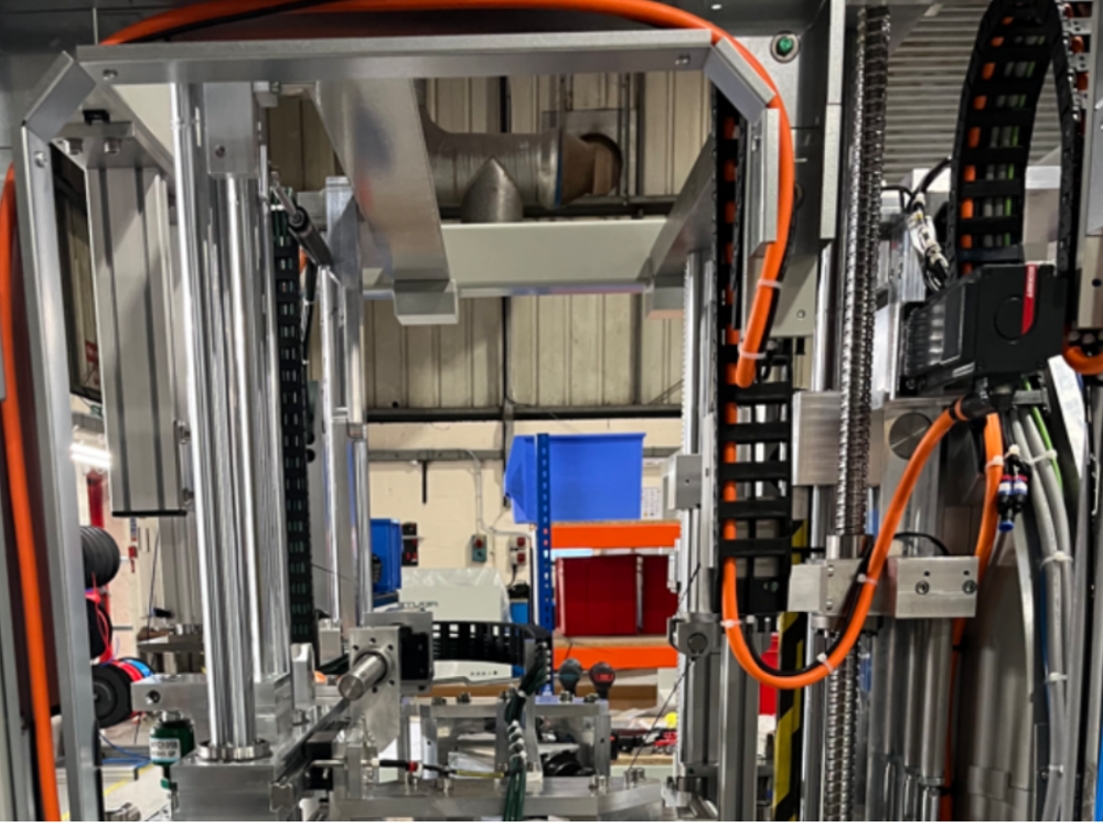
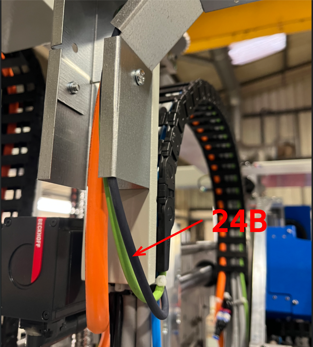
Étape 6 - Loom 24B
Retrieve 24B cable which exits the rotary head energy chain and loom to box FB04B out port

Étape 7 - Route X53 Z axis Datum
Route X53 cable as shown, to EC04B


Étape 8 - Route X488 and X56
Retrieve X488 and X56 from rotary ring loom and route around trunking to EC04B


Étape 9 - Route X50
Retrieve X50 from energy chain rear and route as shown, exiting at FB04B


Étape 10 - X65 CLISHm
Route reed switch X65 as shown. Finish at FB04B
Ensure maximum length is left for routing to cylinder at a later point
Étape 11 - X63 CLITHm
Route X63 reed switch to the route shown, leaving minimal cable for termination at FB04B end

Étape 12 - X59 X61
Route reed switches X59 and X61 from FB04B to exit at point shown of trunking
Ensure minimal length of cable is left at FB04B termination end


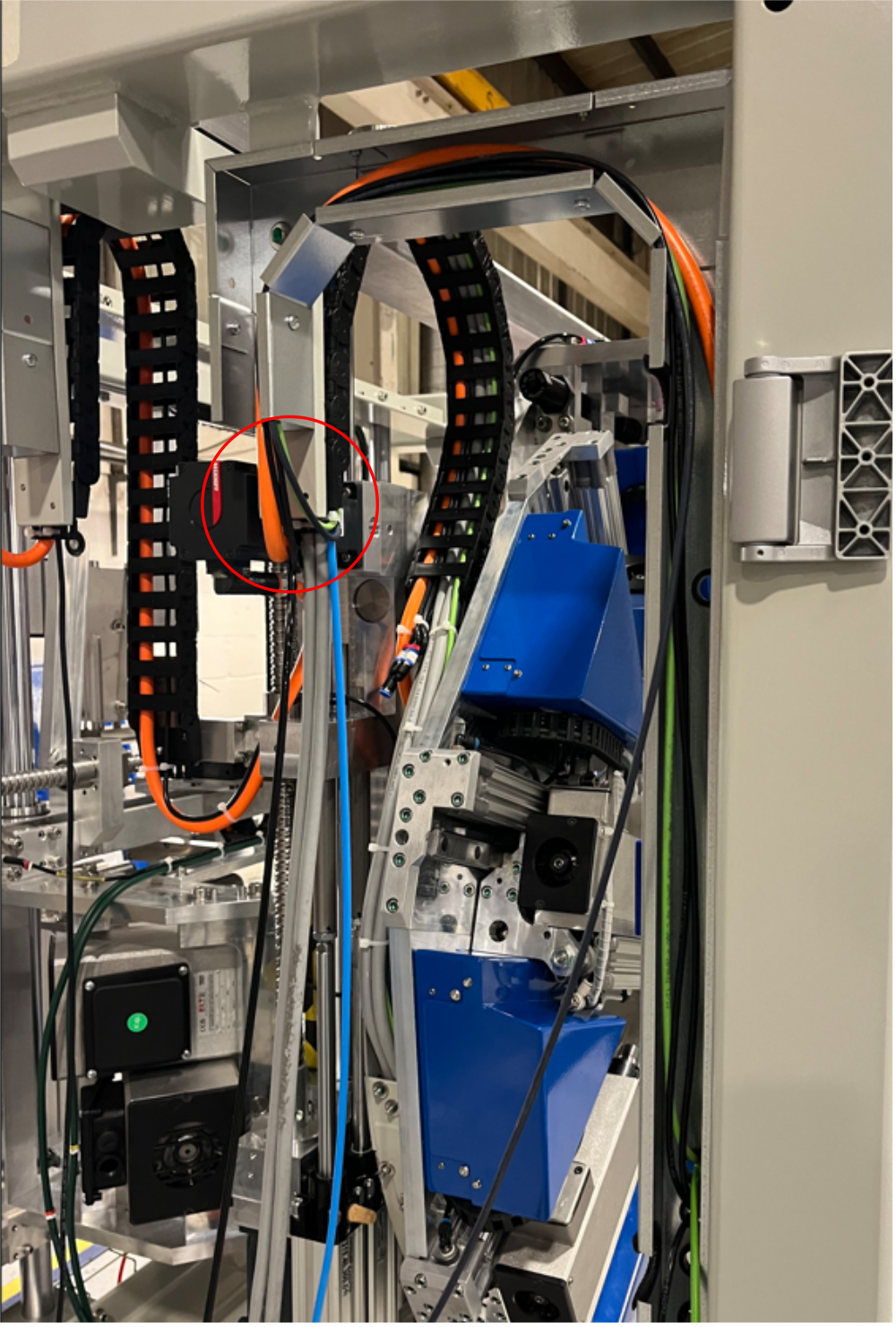
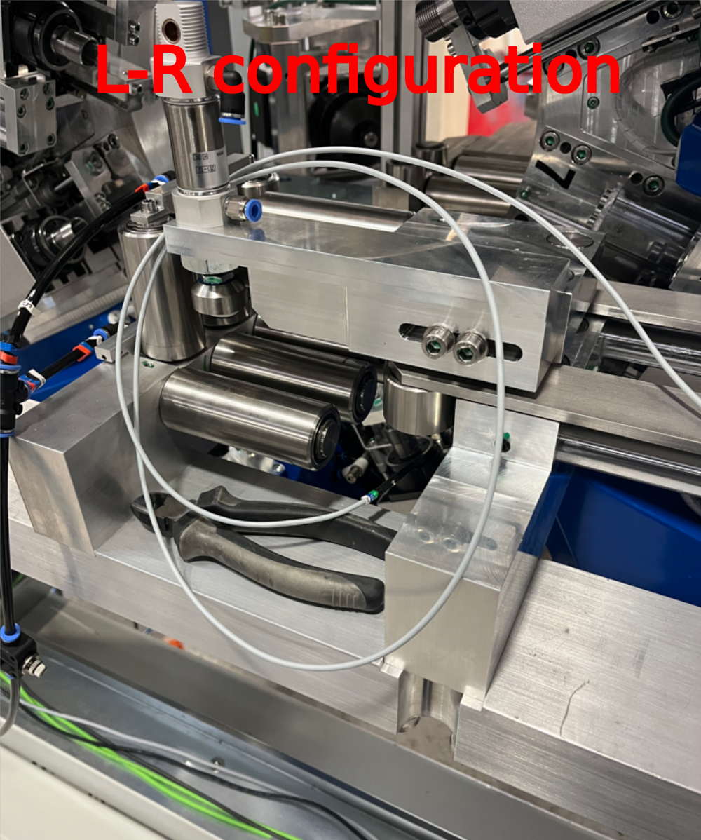
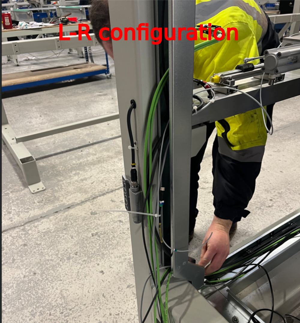
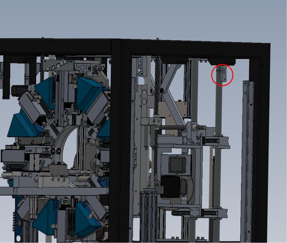
Étape 13 - Route X247
Connect X247 from loom box onto V safe sensor and route as shown to FB01B


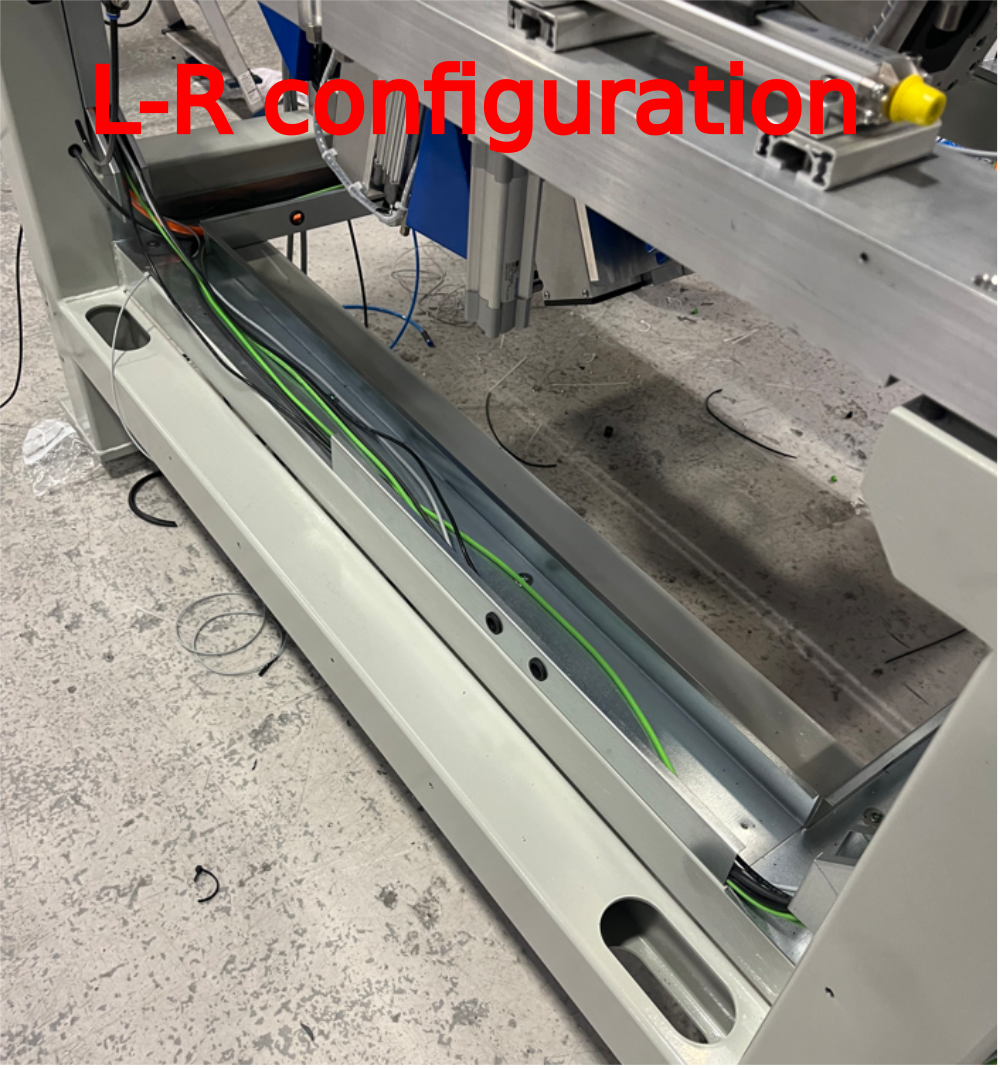
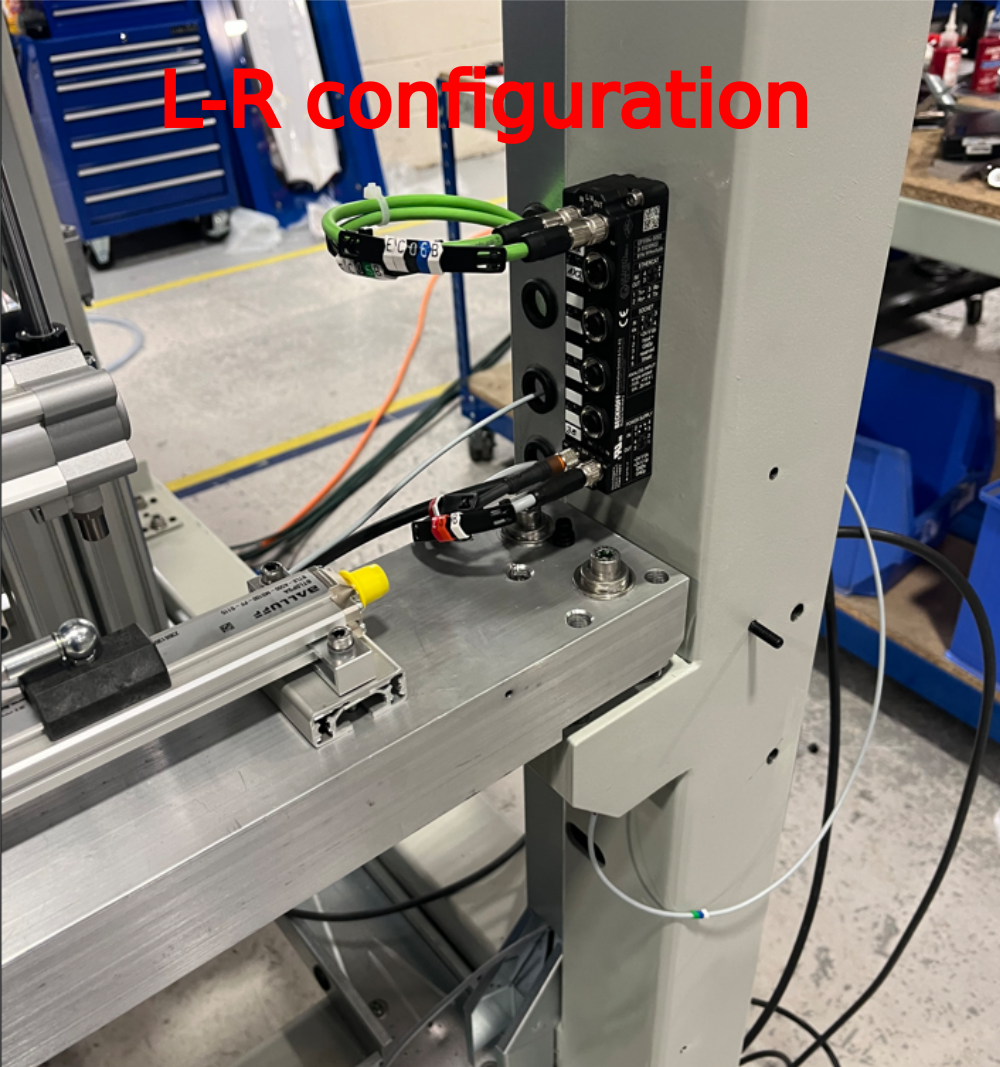
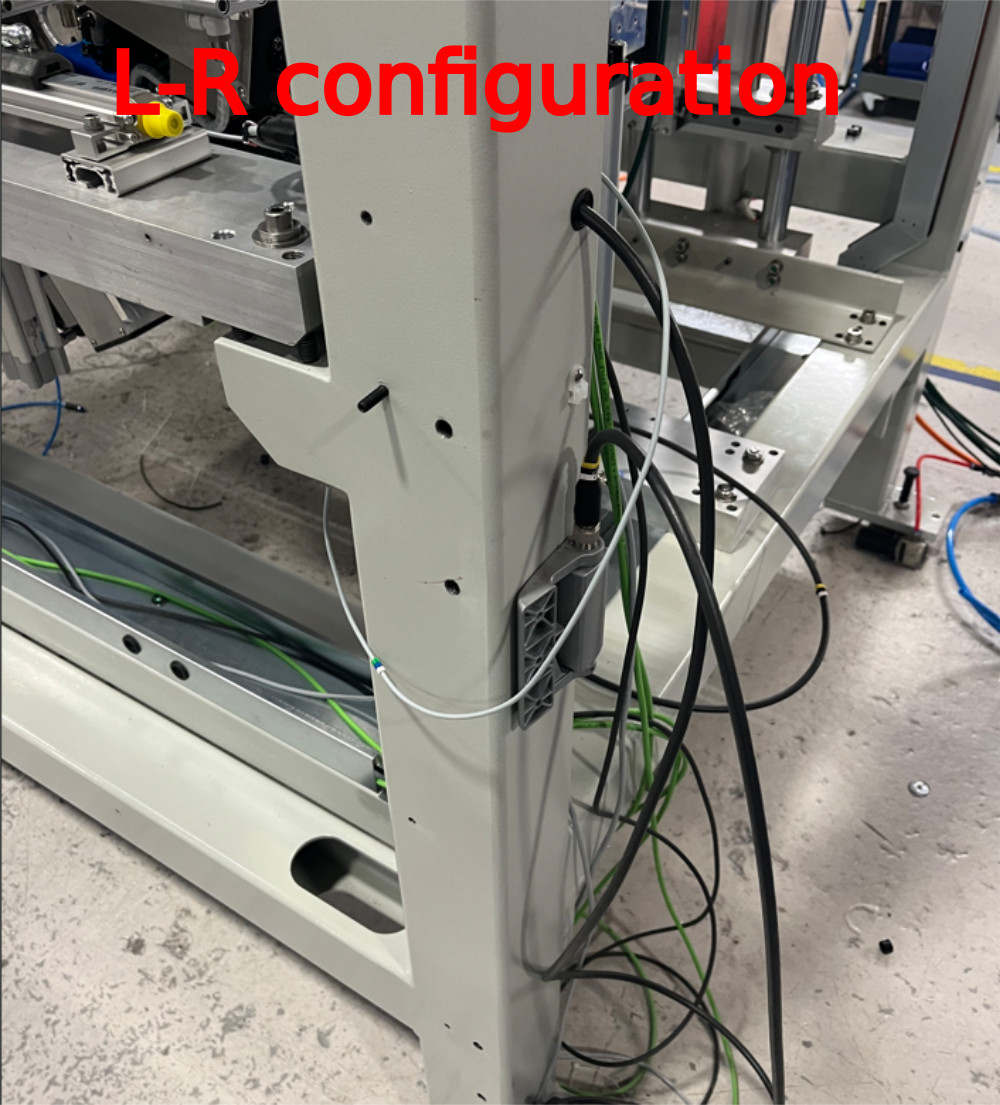
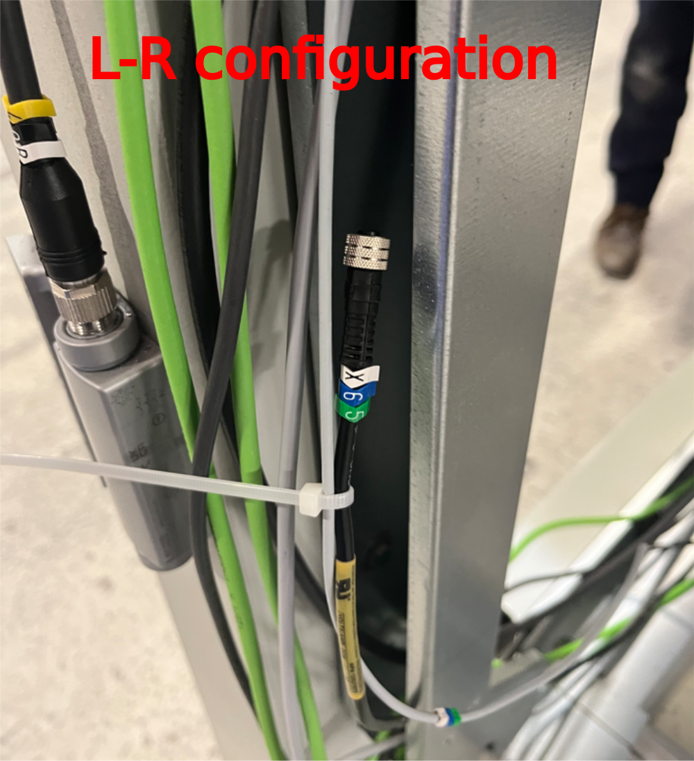
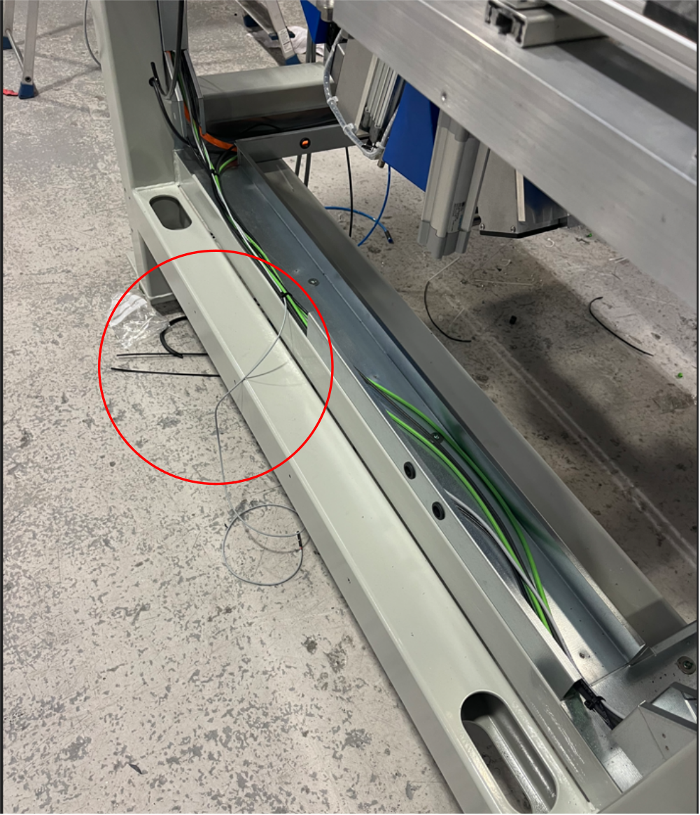
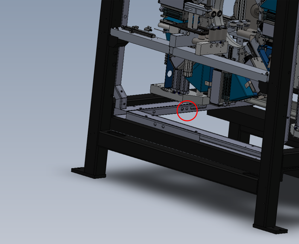
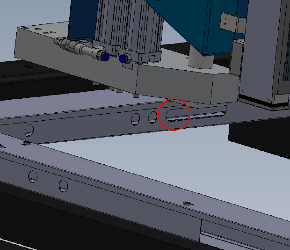
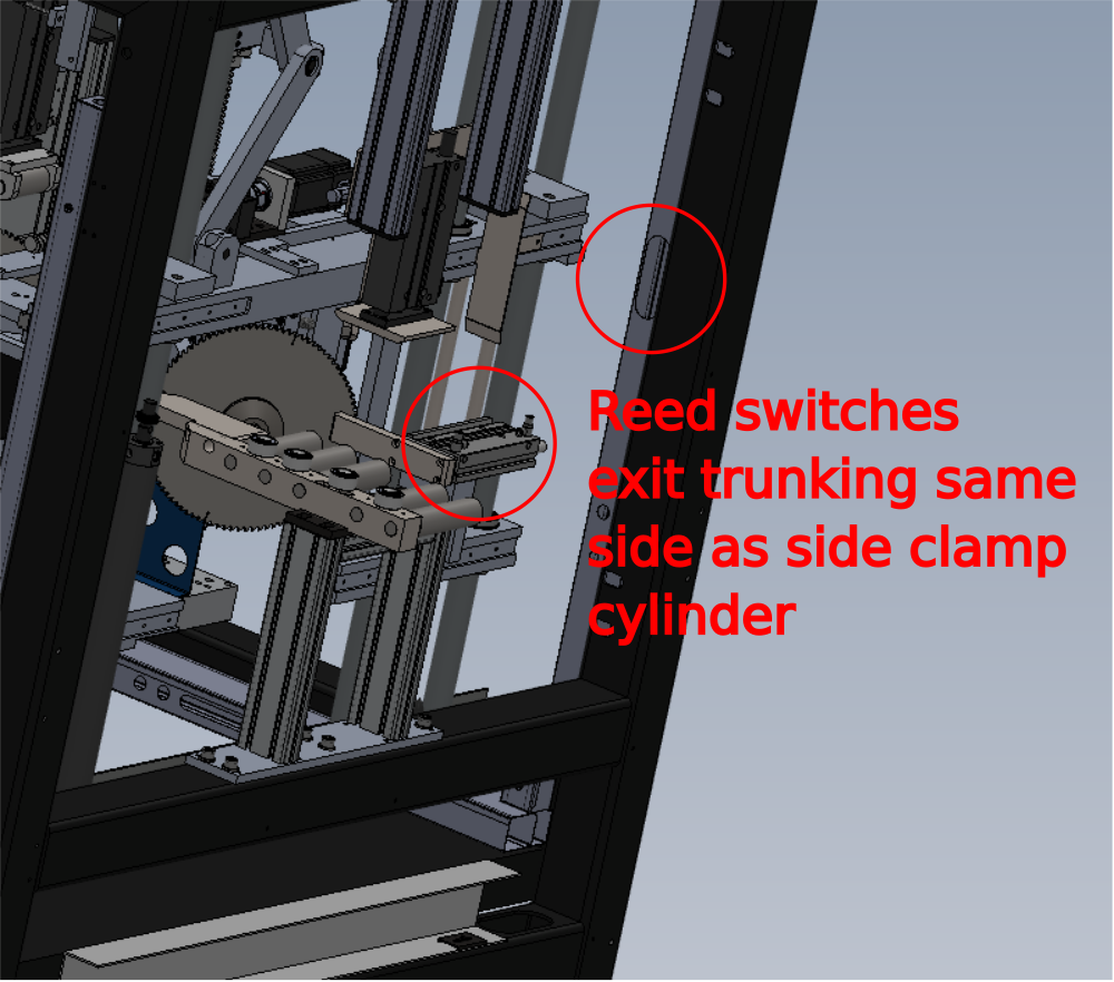
Étape 14 - Route X111 and X112
Route X111 and X112 reed switches from loom box and route as shown
Reed switches to exit same side as cylinders for V notch clamps
Ensure minimal cable length is left at FB01B connection end
Coil reed switches onto cylinder for temporary measure


Draft
 Français
 English
 Deutsch
 Español
 Italiano
 Português