Installation steps for Electrical looms installation into Module B

Difficulté
Difficile
Durée
8 heure(s)
Sommaire
- 1 Introduction
- 2 Étape 1 - Unless otherwise stated
- 3 Étape 2 - Ring Toolbreak connections
- 4 Étape 3 - R axis motor connection
- 5 Étape 4 - Loom Rotary ring cables and pipes
- 6 Étape 5 - Energy chain
- 7 Étape 6 - Route R axis Cable
- 8 Étape 7 - Route Z axis
- 9 Étape 8 - X50 Y axis datum
- 10 Étape 9 - Y Axis servo connection
- 11 Étape 10 - Fit Ethercat Box FB01B
- 12 Étape 11 - Fit Ethercat box FB02B
- 13 Étape 12 - Fit Ethercat FB03B
- 14 Étape 13 - Fit Ethercat FB04B
- 15 Étape 14 - Connect EC07B
- 16 Étape 15 - Connect EC06B
- 17 Étape 16 - Connect EC05B
- 18 Étape 17 - Connect EC04B
- 19 Étape 18 - Connect EC03B
- 20 Commentaires
Introduction
Parts Required
Pre labelled Wiring loom assembly R0015034B from electrical team
Tools required
Flush cutters
Tie wraps small
Tie Wraps Large
Étape 1 - Unless otherwise stated
All bolts to have Loctite 243 adhesive applied unless otherwise stated
All Threaded Pneumatic connections to have Loctite 570 applied
All bolts to be pen marked once adhesive applied and correct tension added

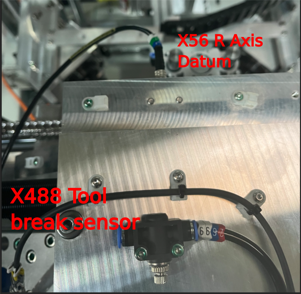
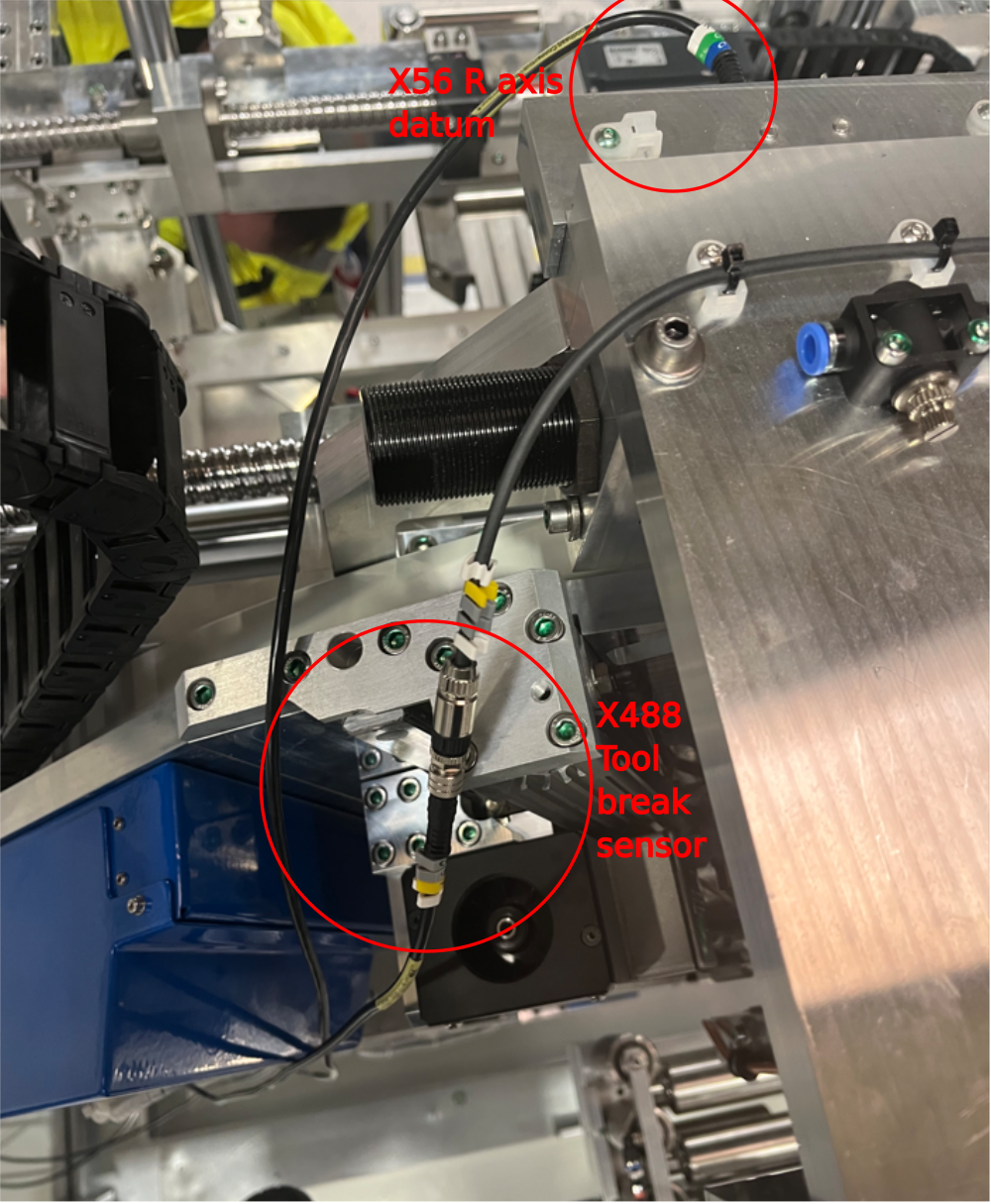
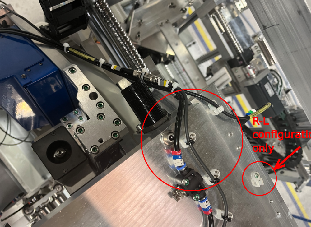
Étape 2 - Ring Toolbreak connections
{Pictures show L-R configuration. For R-L use additional tie base shown
1 Use cables X56 and X488 from loom box.
2 Connect as shown to sensor and flying lead X488
3 Cut and label 1 off 6mm black air pipe 2699 @ 5 mtrs
4 Loom as shown utilising tie bases as indicated

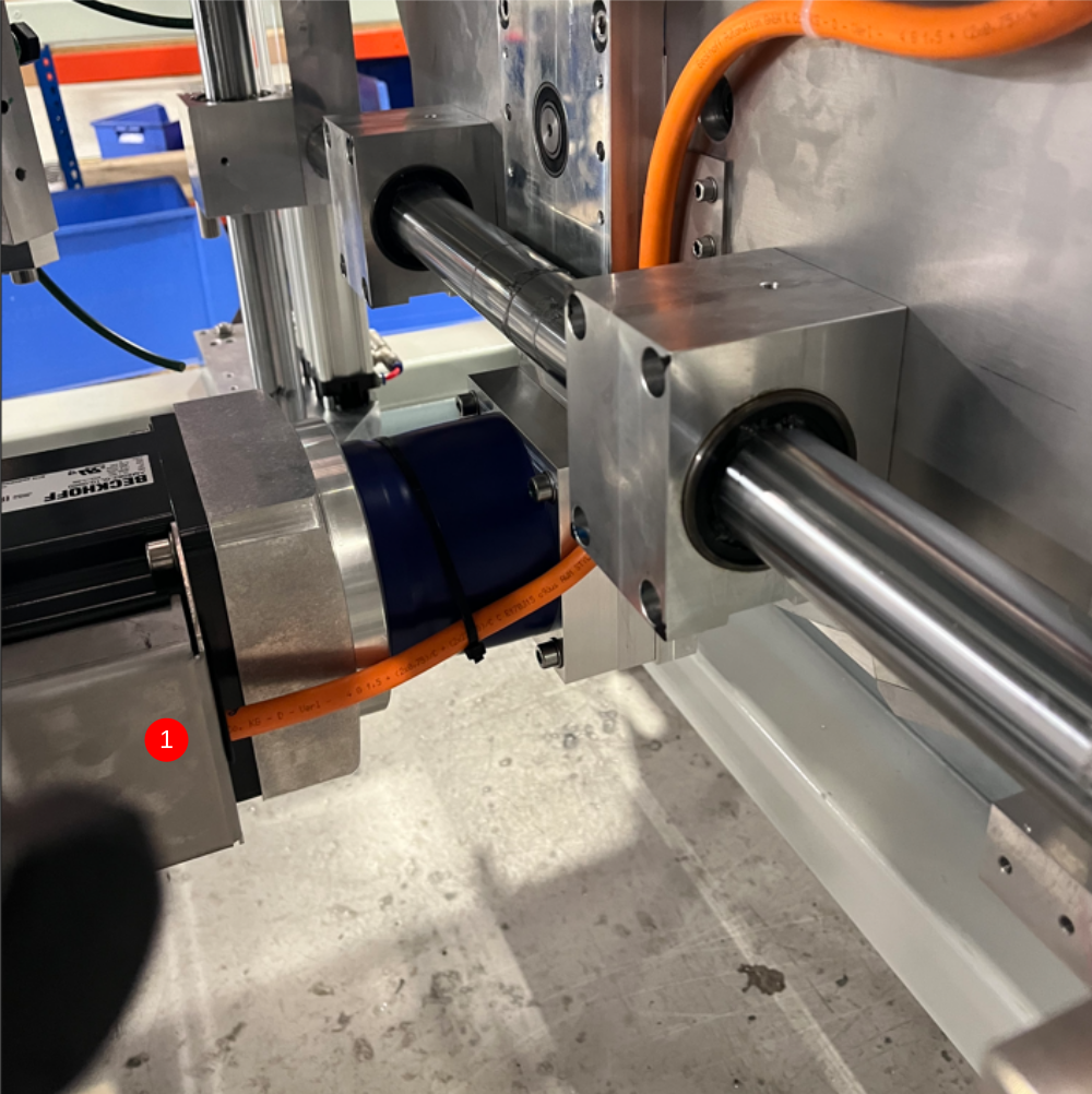
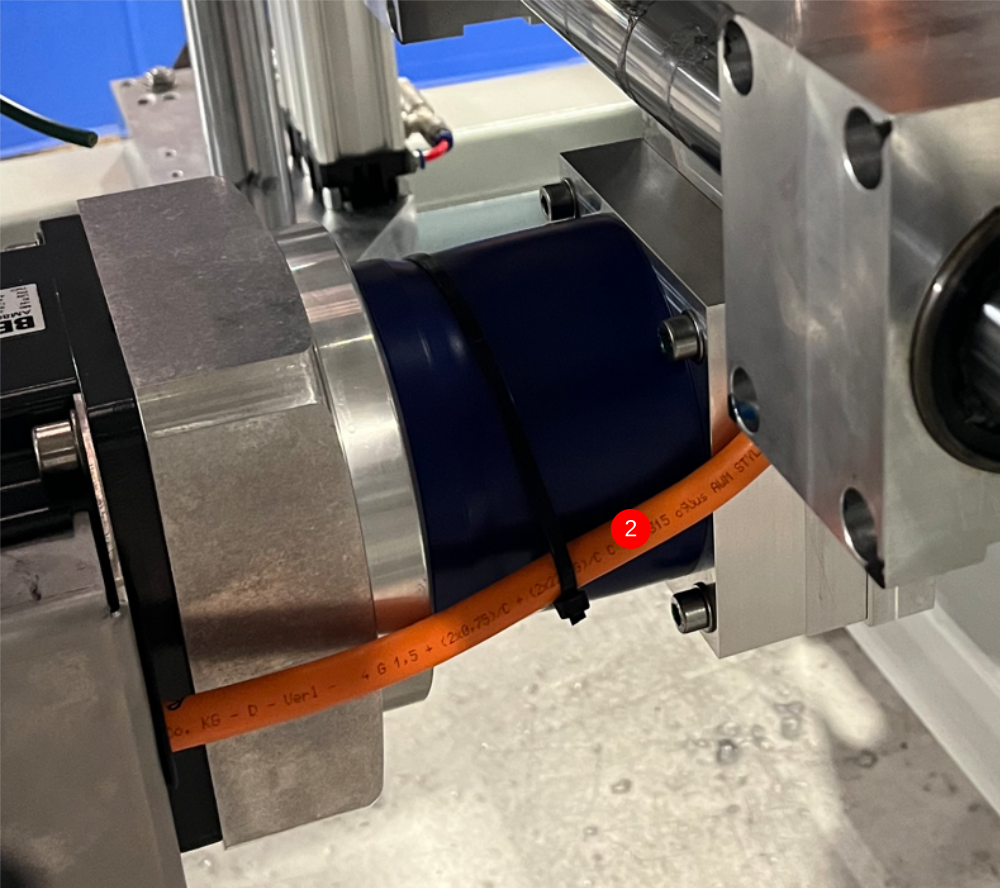
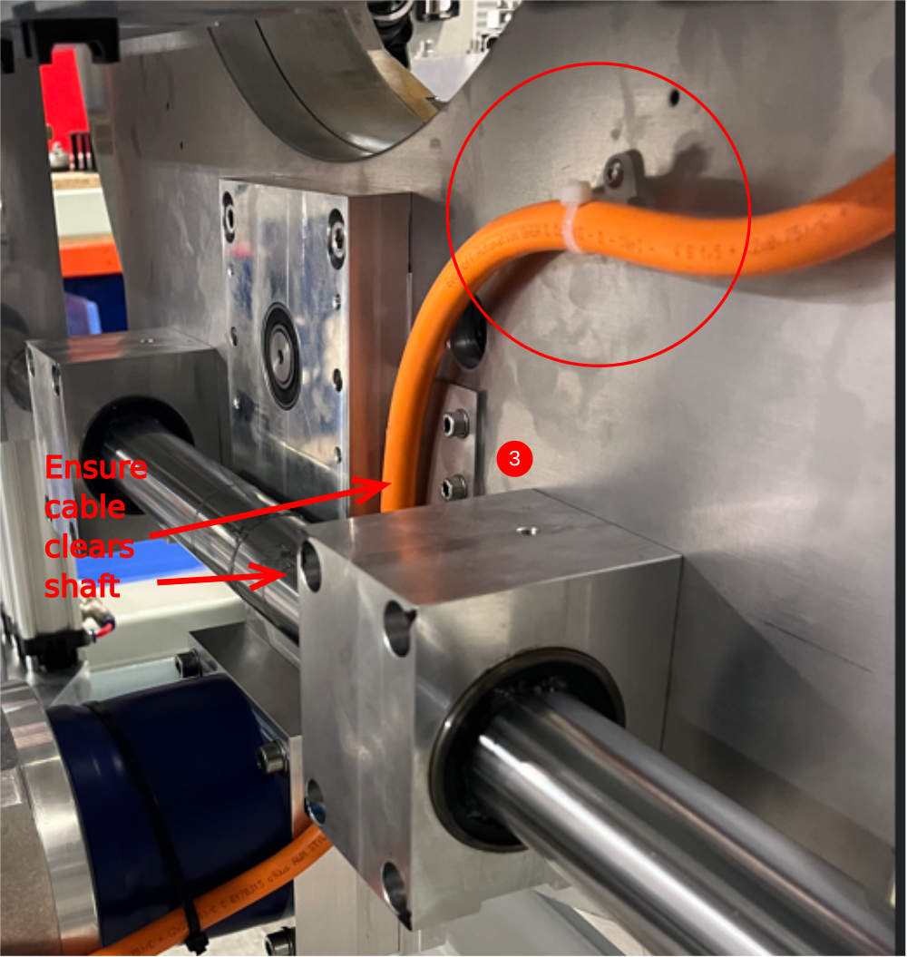
Étape 3 - R axis motor connection
Use cable marked as R axis from loom box
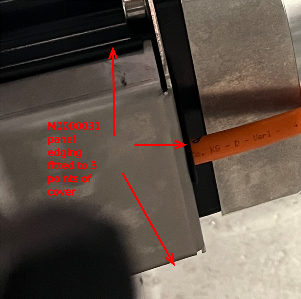
1 Connect to servo motor, and fit protective cover to finalise .Ensure panel edging strip is fitted to indicated faces shown
2 Captivate cable onto gearbox as shown with large tie wraps
3 Fix to rear faceplate using M4 tie base. Ensure cable sits free of main shaft
4 Fix cable as shown using large tie bases
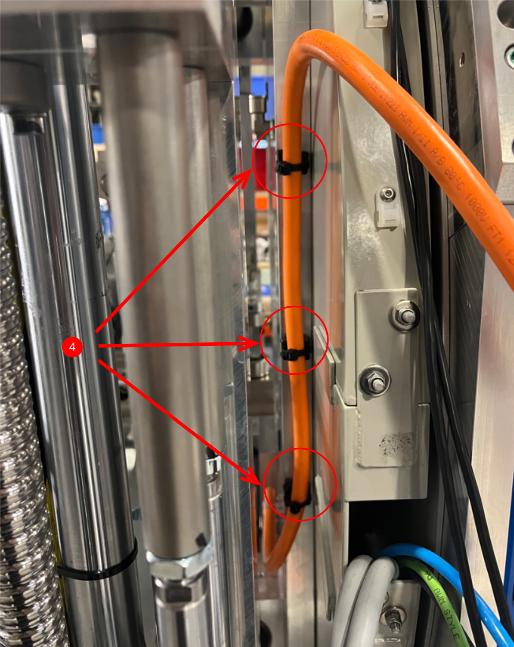
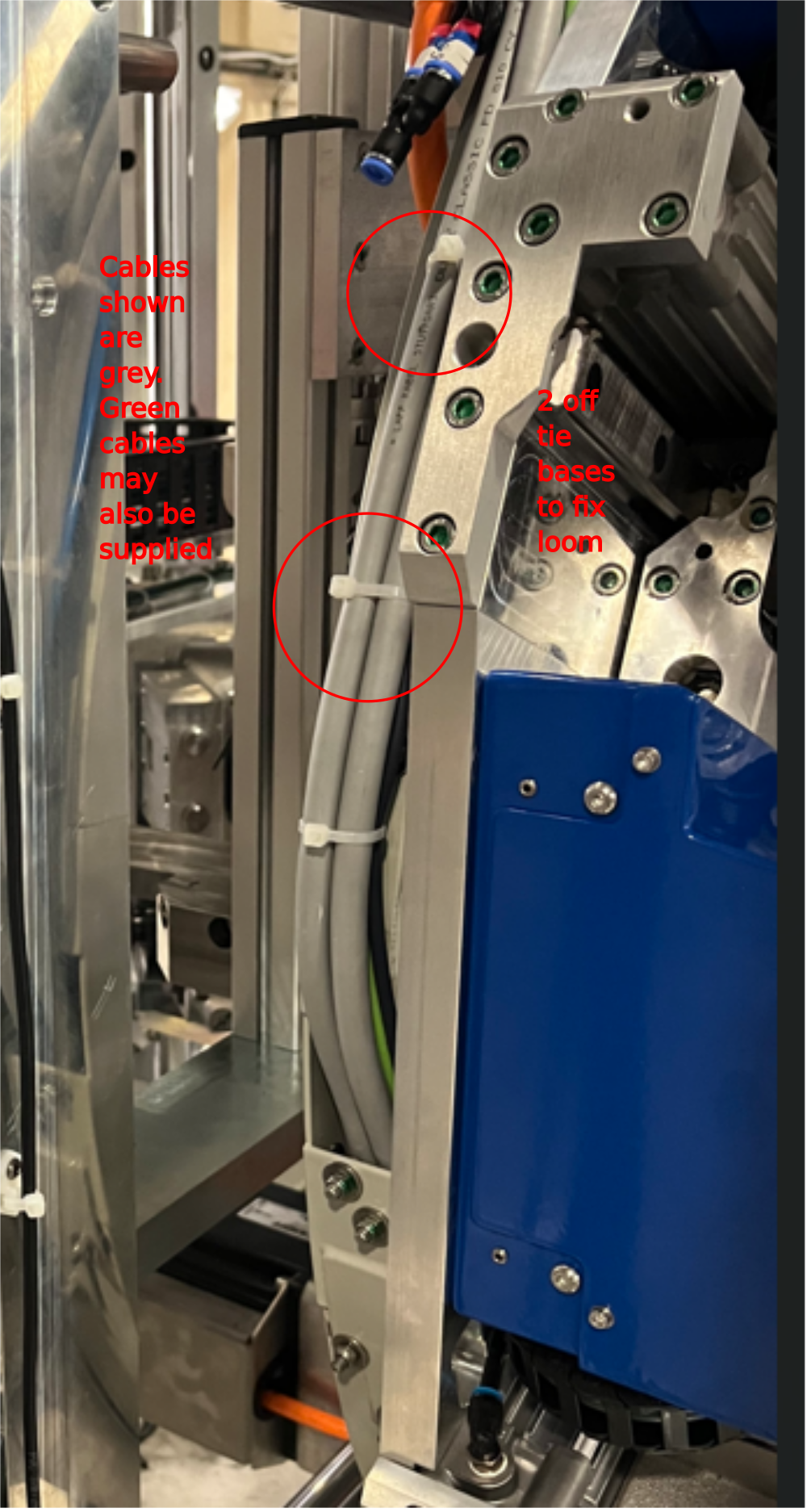
Étape 4 - Loom Rotary ring cables and pipes
Loom cables and pipe from rotary head, fix with 2 off small tie bases
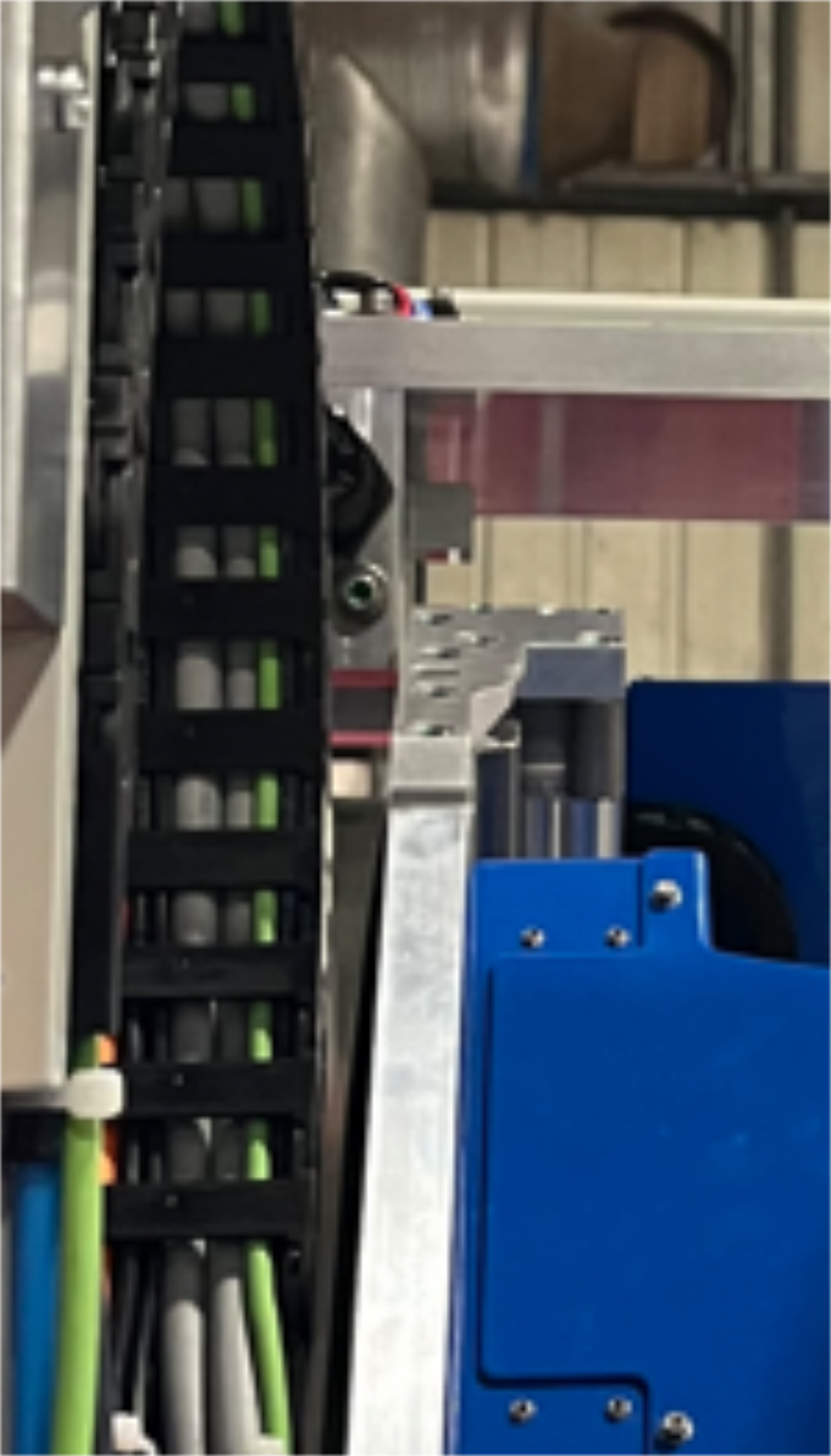
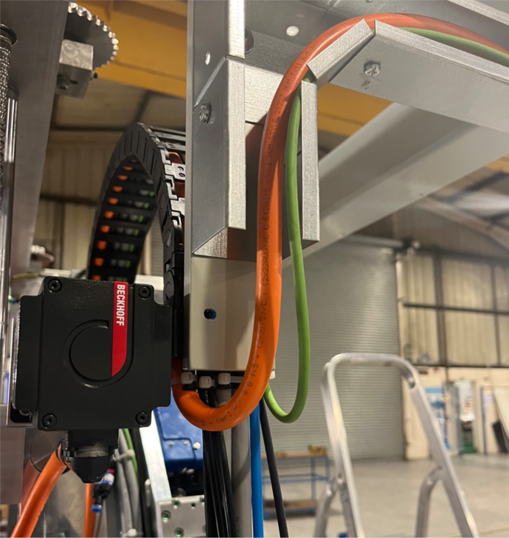
Étape 5 - Energy chain
Run cables from step 2-4 through energy chain, ensuring no twists are present. Cables X56 and X488 and pipe 2699, need to be run through link 2 not the end of the energy chain. Link 2 is the ring end of the energy chain, not the frame end.
Ensure cable retention points are used at both ends of energy chain .
Use P0000046 Y connector and P0000159 6mm blank to direct 2699 pipe as shown ( this is required to ensure pipe does not kink when entering energy chain)
Ensure that rotary head is moved fully in both directions side to side to ensure that loom lengths entering the energy chain are correct and no tension is applied to cable looms
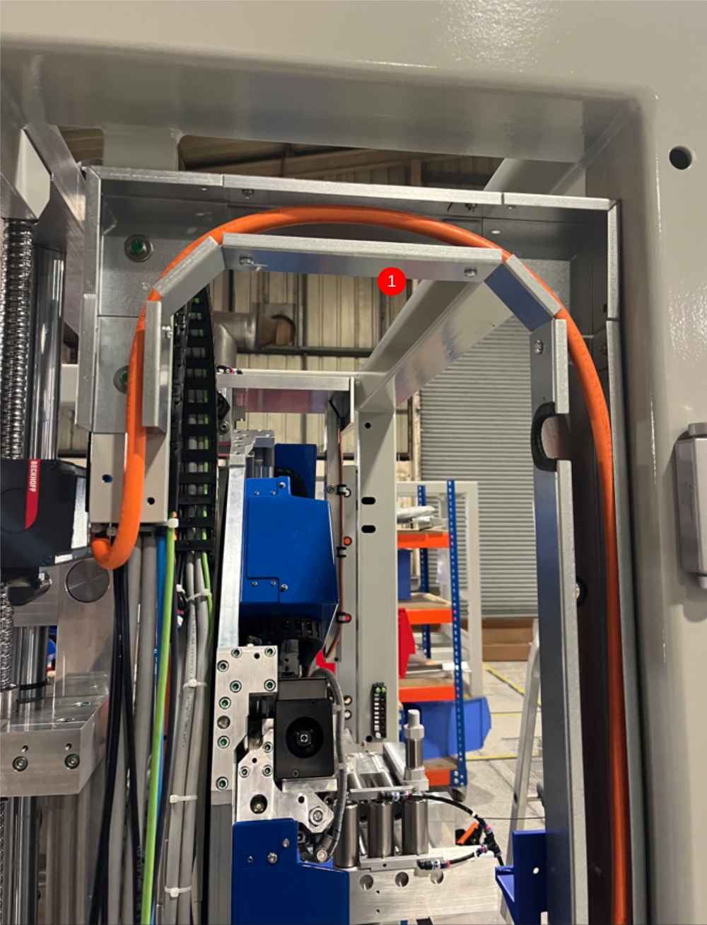
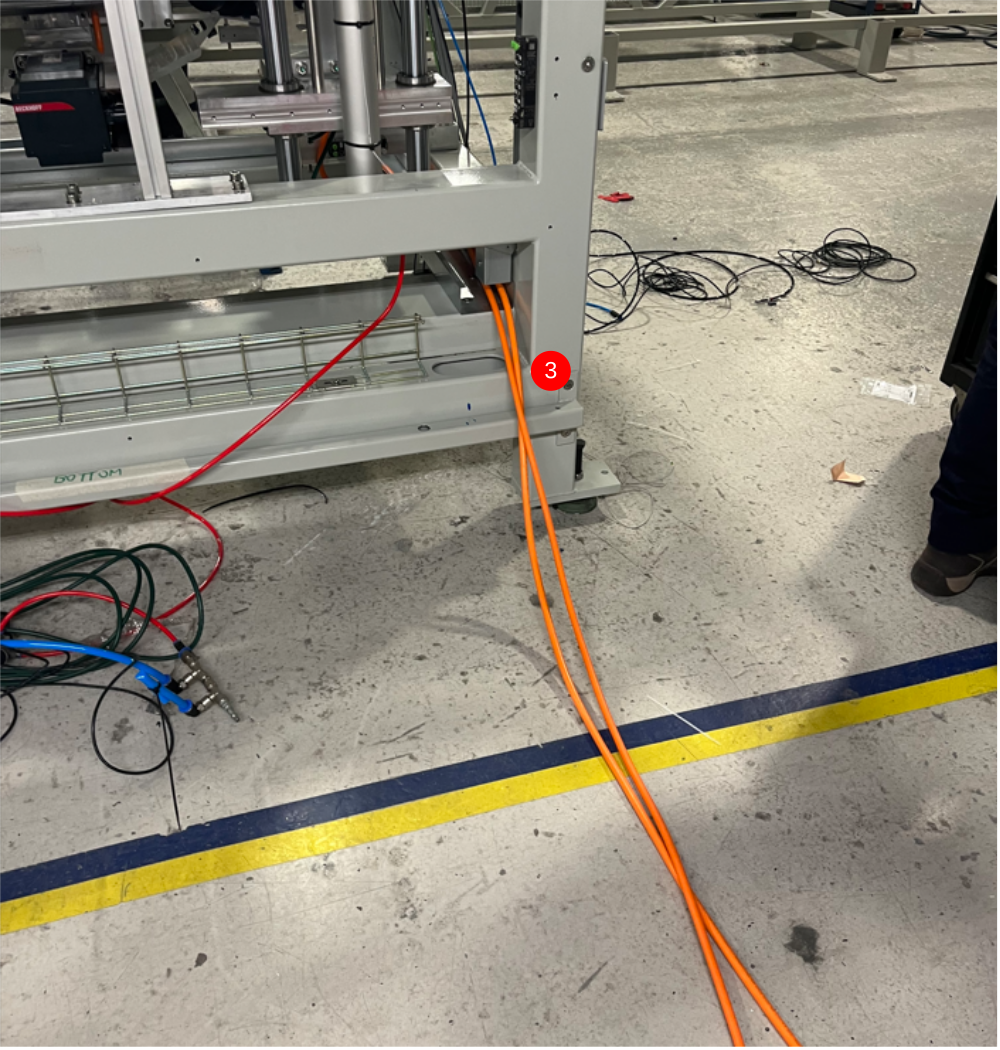
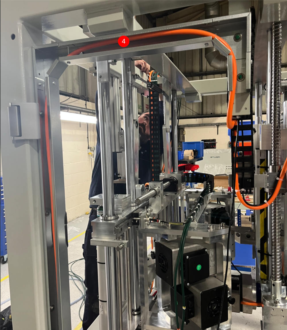
Étape 6 - Route R axis Cable
1 Route R axis cable as shown through trunking
2 Pass large servo plug through vertical trunking dogleg .
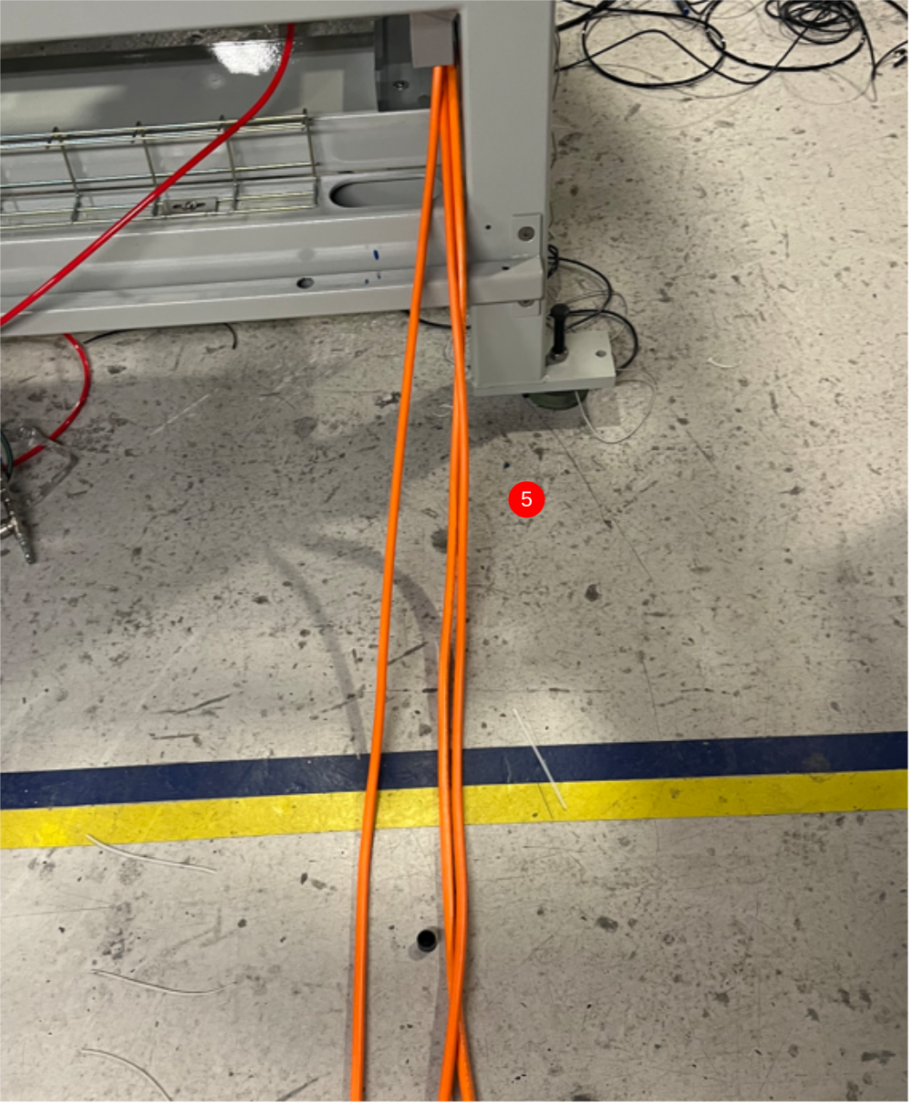
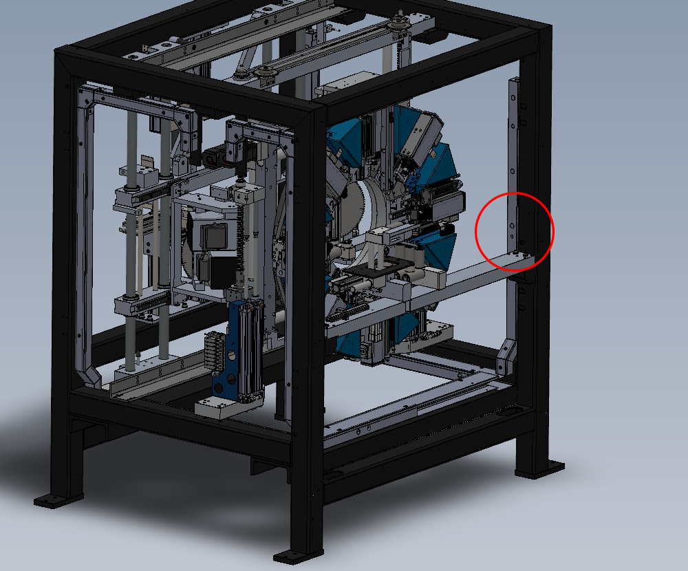
3 Exit cable from frame at rear as shown
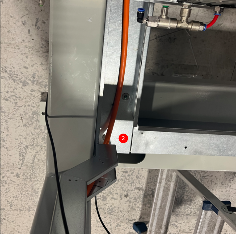

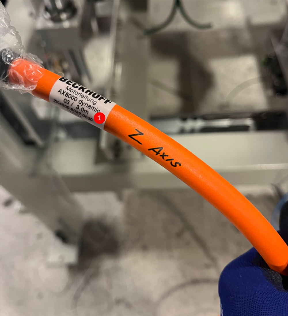
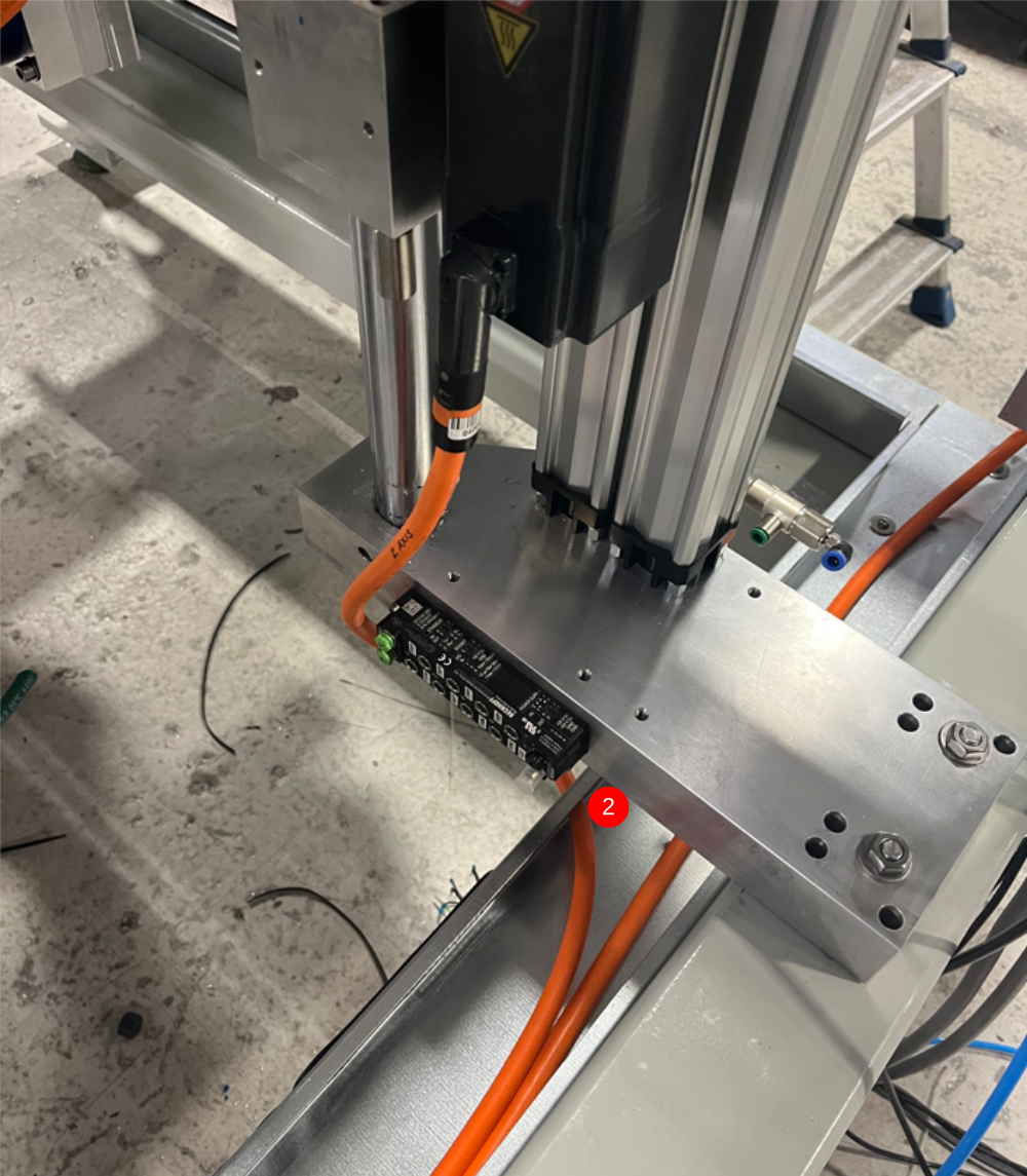
Étape 7 - Route Z axis
1 Retrieve cable identified as Z axis from loom box
2 Pass small plug through trunking grommit shown and connect to servo motor
3 Route and exit rear as shown
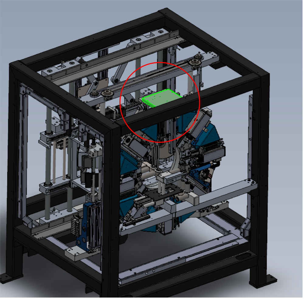
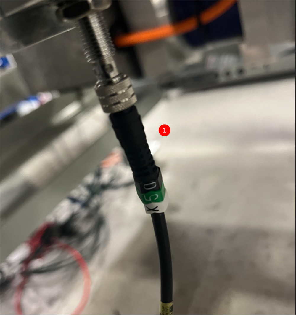
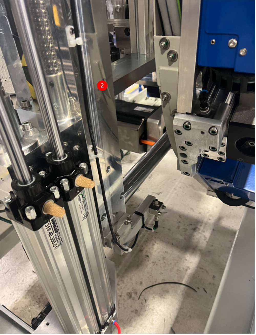
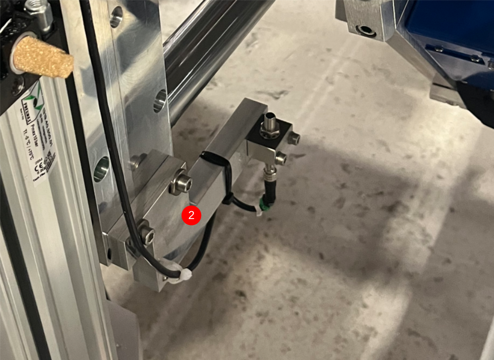
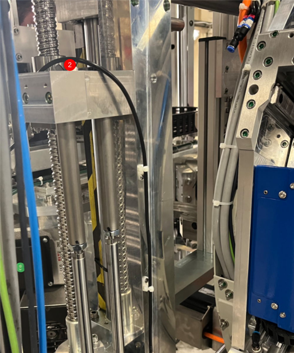
Étape 8 - X50 Y axis datum
1 Retrieve X50 from wiring loom box , and Fit to Y axis datum point
2 Attach cable tie bases small and route cable as shown
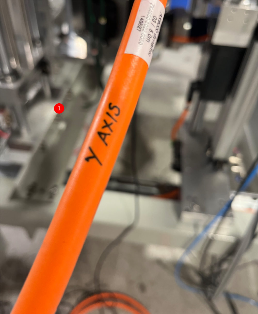
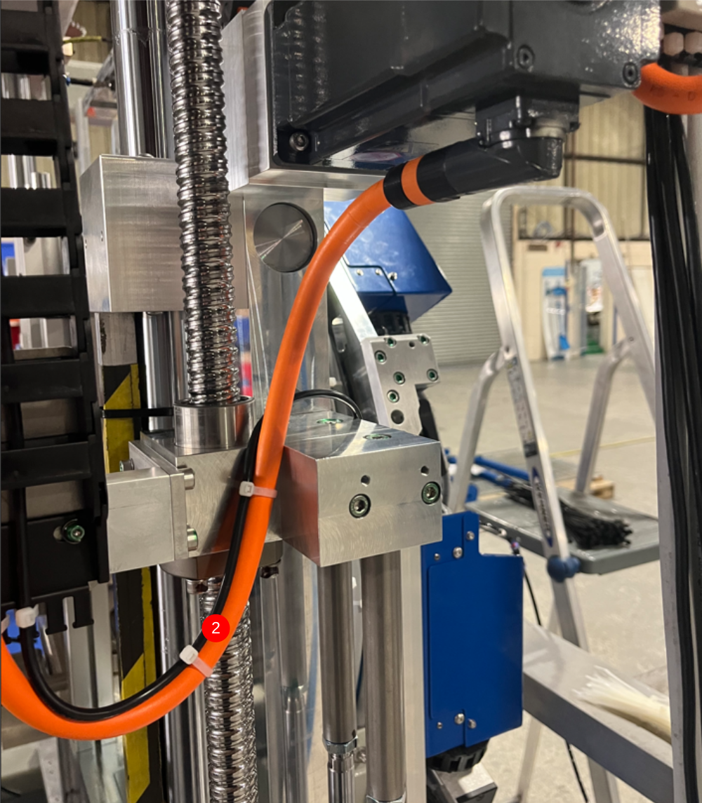
Étape 9 - Y Axis servo connection
1 Identify Y axis cable from loom box
2 Connect and loom as shown , incorporating previous fitted X50 cable
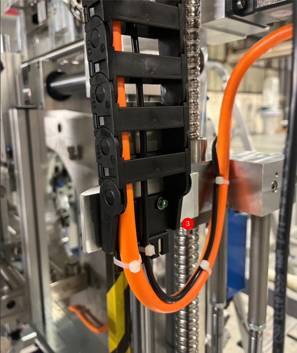
3 Run through energy chain as shown, ensure cable retention points are used
4 Route servo cable through trunking as shown
5 Exit machine at rear as shown
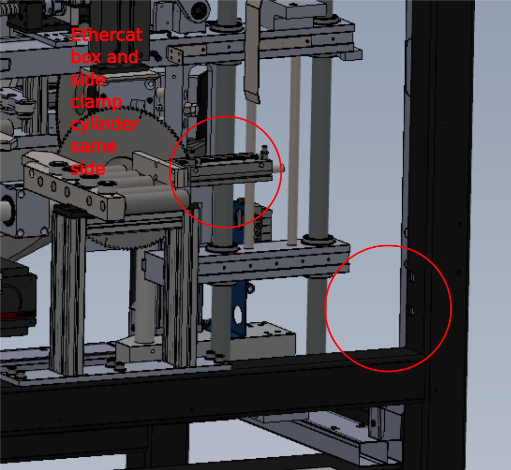
Étape 10 - Fit Ethercat Box FB01B
Fit C0001018 from wring loom box to area shown . Must be fitted to same side as clamp assembly
Use 2 off m3 x 20 pan heads to fix
See diagram for clarity
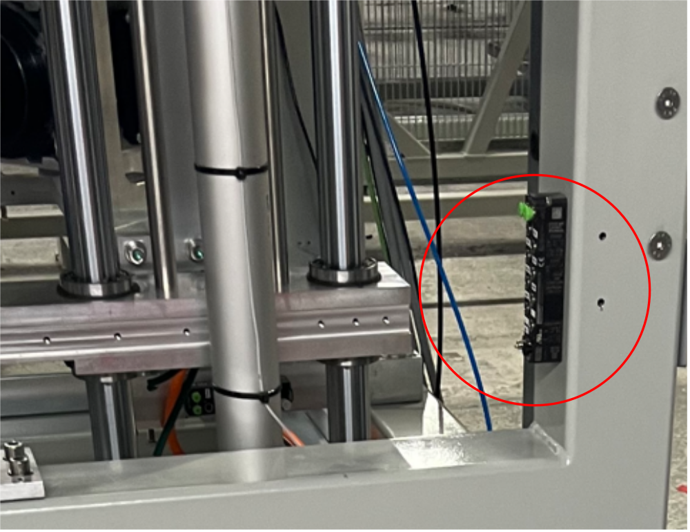
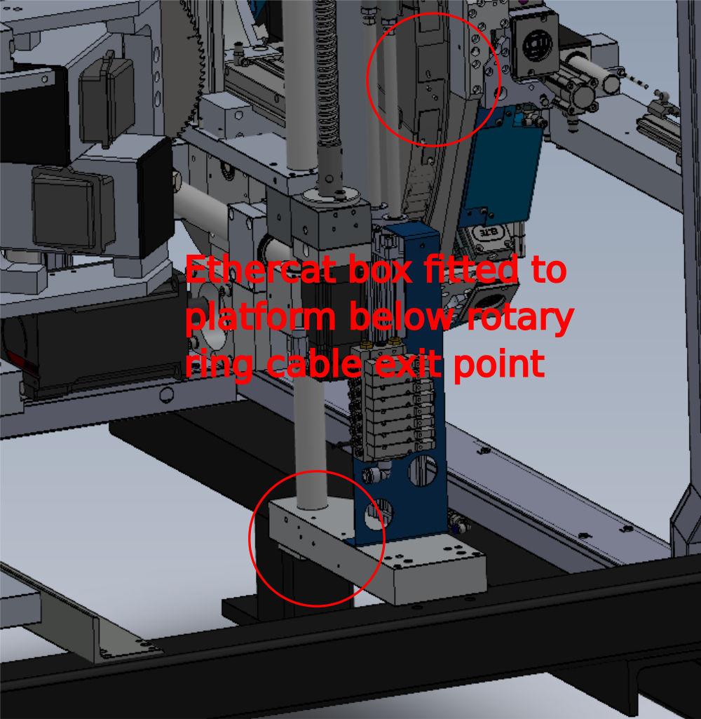
Étape 11 - Fit Ethercat box FB02B
Fit C0001018 from wring loom box to area shown
Must be fitted to same side as rotary ring cable exit point
This position does not change with L-R or R-L variants
Use 2 off m3 x 20 pan heads to fix
See diagram for clarity

Étape 12 - Fit Ethercat FB03B
Fit c0001129 ethercat box from wiring loom assembly to point shown
This position does not change with L-R or R-L variants
Use 2 off m3 x 20 pan heads to fix
See diagram for clarity

Étape 13 - Fit Ethercat FB04B
Fit C0001018 from wring loom box to area shown
This position does not change with L-R or R-L variants
Use 2 off m3 x 20 pan heads to fix
See diagram for clarity

Étape 14 - Connect EC07B
Loom Cable EC07B from trunking as shown and connect to out port on FB04B


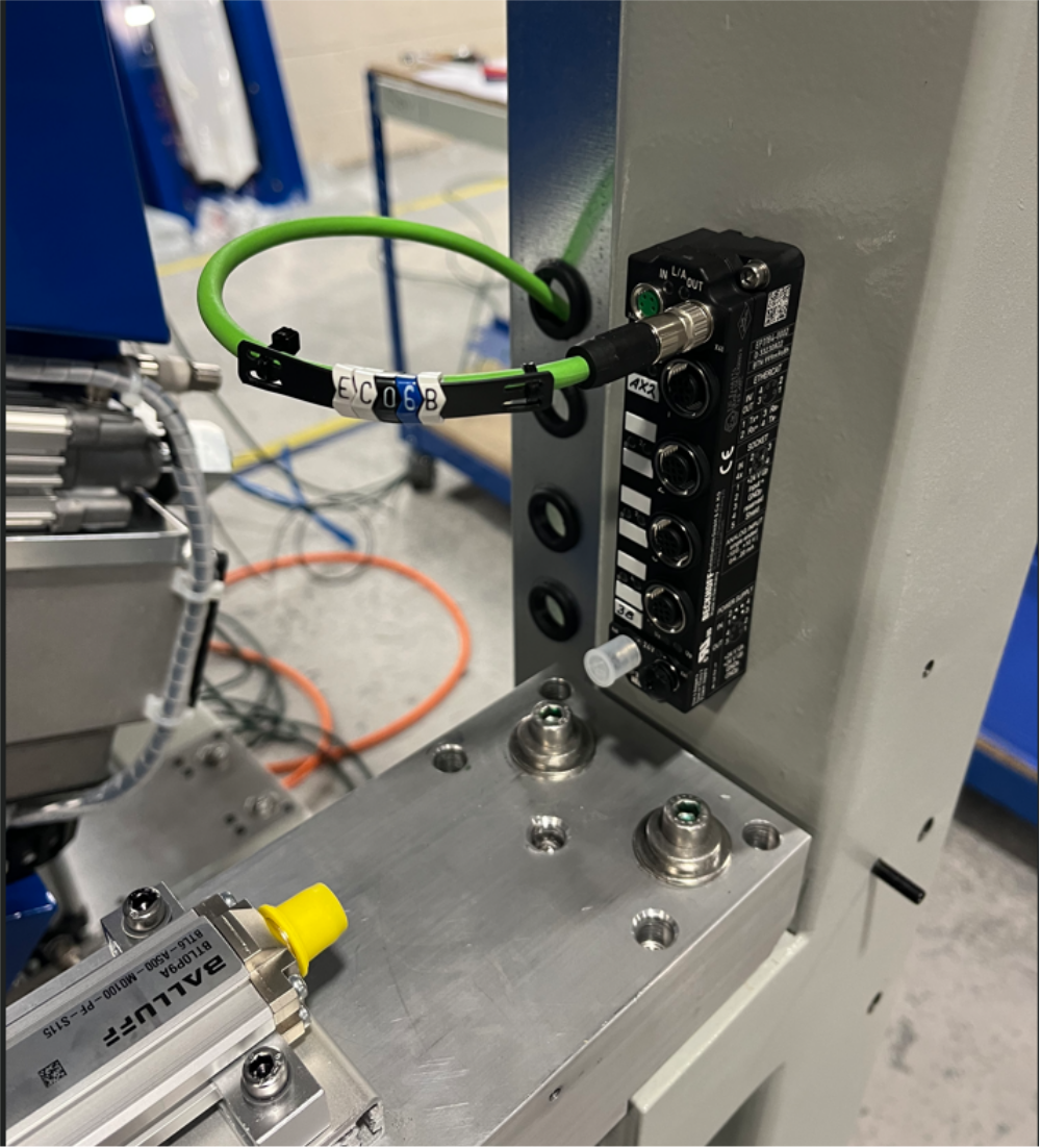
Étape 15 - Connect EC06B
Loom Cable EC06B from FB04B in port to FB03B out port as shown


Étape 16 - Connect EC05B
Loom Cable EC05B from FB03B in port to FB02B out port as shown


Étape 17 - Connect EC04B
Loom Cable EC04B from FB02B in port to FB01B out port as shown


Étape 18 - Connect EC03B
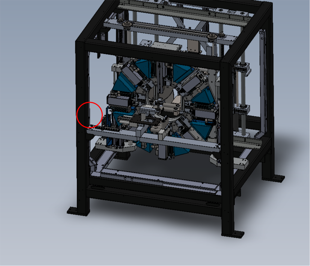
Loom Cable EC03B from FB01B in port to shown exit point on frame


Draft
 Français
 English
 Deutsch
 Español
 Italiano
 Português