| [version en cours de rédaction] | [version en cours de rédaction] |
| Ligne 5 : | Ligne 5 : | ||
|Categories=Production | |Categories=Production | ||
|Difficulty=Very hard | |Difficulty=Very hard | ||
| − | |Duration= | + | |Duration=12 |
|Duration-type=hour(s) | |Duration-type=hour(s) | ||
}} | }} | ||
Version actuelle datée du 3 avril 2024 à 12:30
Instructions to correctly align and mount hepco drive beam

Difficulté
Très difficile
Durée
12 heure(s)
Sommaire
- 1 Introduction
- 2 Étape 1 - Unless otherwise stated
- 3 Étape 2 - Please note
- 4 Étape 3 - Attach Setting jigs
- 5 Étape 4 - Level Setting Jigs
- 6 Étape 5 - Level x axis between jigs
- 7 Étape 6 - Wire line for setting straightness
- 8 Étape 7 - Quality Check
- 9 Étape 8 - Additional spacer
- 10 Étape 9 - Position Hepc double edge slide
- 11 Étape 10 - Mechanically join Hepco beam
- 12 Étape 11 - Set beam position
- 13 Étape 12 - Assemble carriage
- 14 Étape 13 - Set journals
- 15 Étape 14 - Fit wipers and finalise
- 16 Étape 15 - Refit carriage plate
- 17 Étape 16 - Check level of carriage plate
- 18 Étape 17 - 1st stage levelling
- 19 Étape 18 - 2nd stage leveling if required
- 20 Étape 19 - Laser checks
- 21 Commentaires
Introduction
Tools Required
Engineers level
Hepco flat spanner
Hepco Box spanner
Standard hex key set
Incremental shim pack
Torque wrench
Parts Required
B0000184 Journal Cap Seal 34 x 4
B0000185 Double Row Long Stud Journal Eccentric x 2
B0000186 Double Row Long Stud Journal Concentric x2
B0001102 Double Edge Spacer Slide and Beam 7600mm x 1
D0015072 Carriage Plate x 1
D0015492 Vertical Beam Adjustment Plate x5
D0015493 Lateral Beam Adjustment Plate x 5
P0000200 Elbow Adaptor 6mm - M5 x 1
F0000529 T-Nut M6 (slot 10) x 3
F0000530 T-nut M8 (slot 10) x1Étape 1 - Unless otherwise stated
Always Use Loctite 243 on all fasteners
Always use Loctite 570 on all threaded pneumatic connections
Pen mark all fasteners to show finalised

Étape 2 - Please note
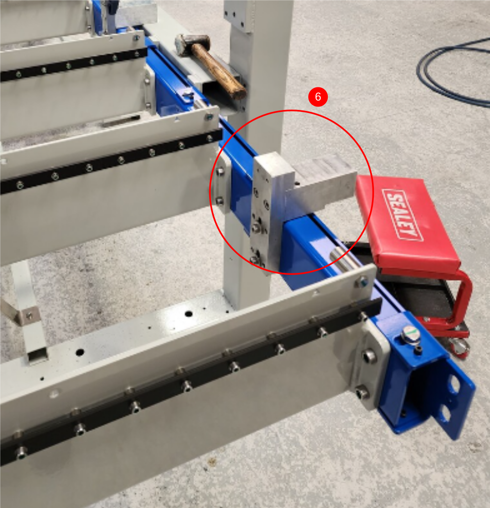
Following step has been amended to include the use of 6 setting jigs

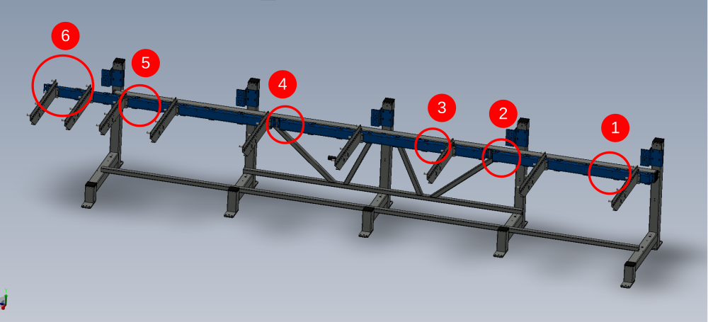
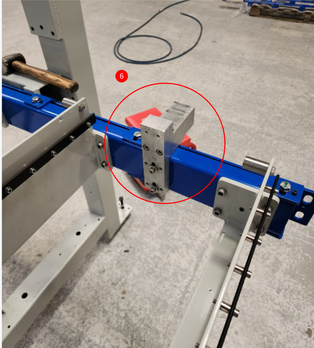
Étape 3 - Attach Setting jigs
Mount setting jigs to channel section in positions shown using M8 cap head bolts and heavy washers
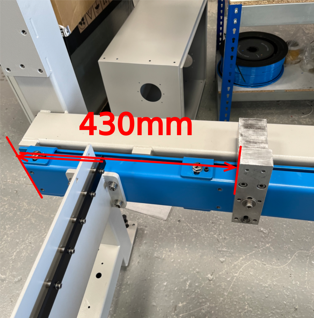
Position one shown will require fixing points drilling to channel section . Drill M8 and position to measurement shown of 430mm
Étape 4 - Level Setting Jigs
Use an engineers level to individually adjust each jig to be level on both axis


Étape 5 - Level x axis between jigs
Using a 2 meter straight edge , the jigs should be levelled to each other as shown.
Identify which Jig is the lowest point by using the straight edge and level . Adjust the lower height jigs to match the highest point one. This is to ensure that the height is maintained as much as possible between blue mounting bar and jig top face
When a jig is adjusted for height, i will need rechecking to see if the other previous levelled plains have moved. If so, re adjust to bring jig level in all axis


Étape 6 - Wire line for setting straightness
A wire line should be used for setting the straightness of the jigs along the x axis
Use dokit Alignment guide using wire line for correct process to set up


Étape 7 - Quality Check
Qc Double check required at this point from Supervisor that all alignment is correct.

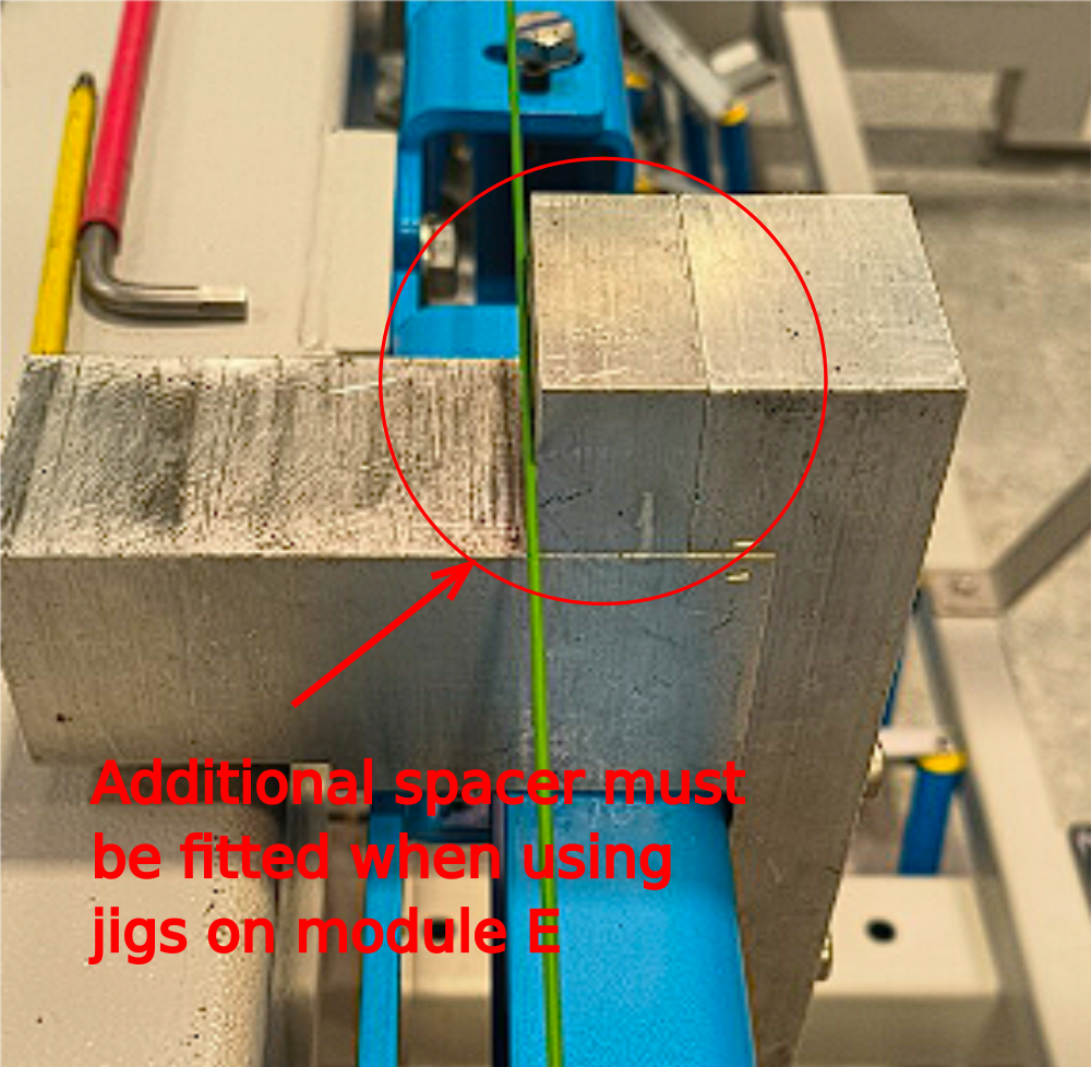
Étape 8 - Additional spacer
Ensure additional spacer is fitted to jigs when using for alignment on module E
Étape 9 - Position Hepc double edge slide
B0001102 can now be assembled on jigs .
These beams are paired so check you have been issued a set correctly
Pairs can be identified as follows
1 and 1
2 and 2
A and A
B and B


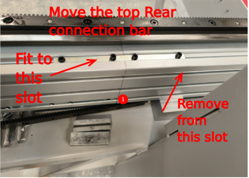
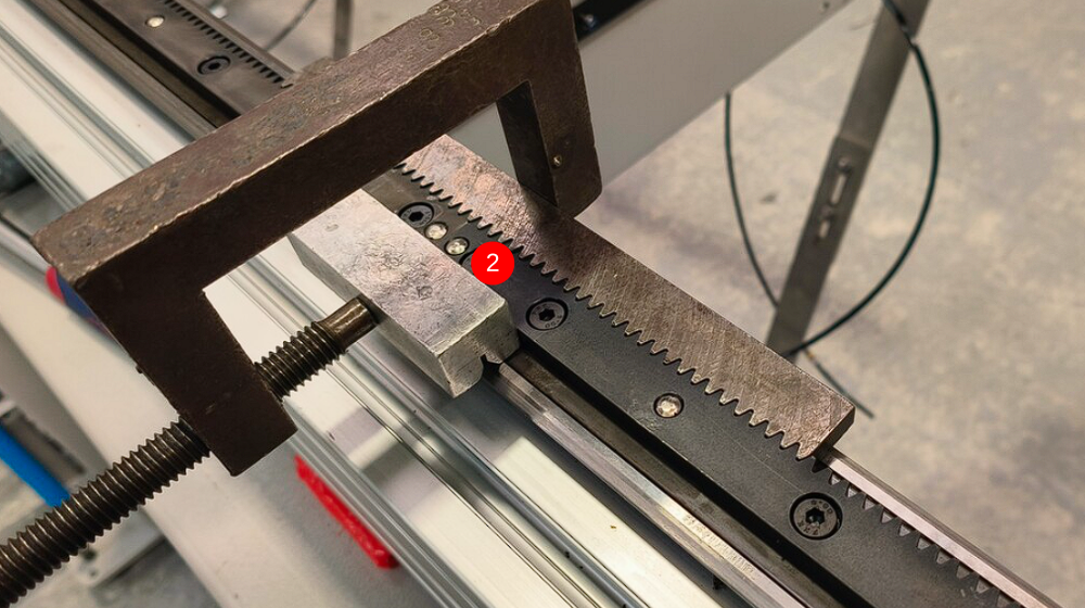
Étape 10 - Mechanically join Hepco beam
1 Move one off joining bar as shown . do not tension bars yet
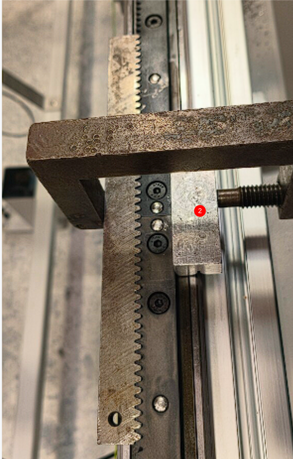
2 Use jig shown to ensure correct pitching of 2 sections of drive rail when coupled together
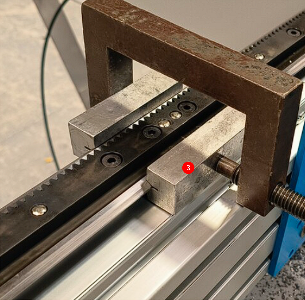
3 Use v blocks to ensure alignment of V's on hepco rail are correct when mating the two parts
4 Tension all fasteners on hepco rail to secure positions of hepco rails in relation to each other ( DO NOT FIT DOWELS AT THIS POINT NEW PICTURE REQUIRED )
5 Tension joining bars
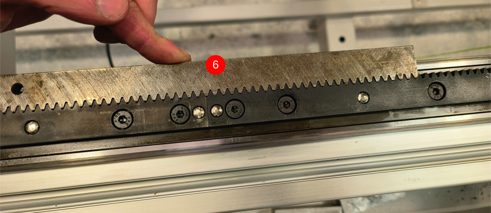
6 Check correct pitching by using toothed jig again once all fasteners are tensioned. Toothed jig should lay flat with no rock when laid against toothed rail as shown
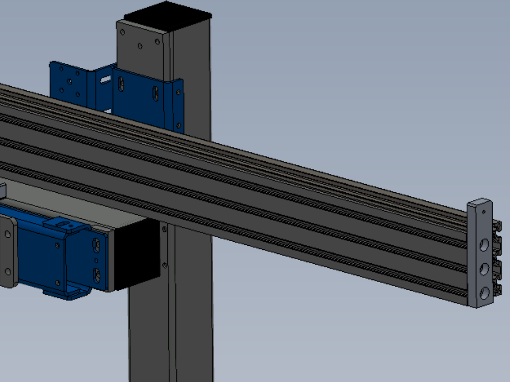
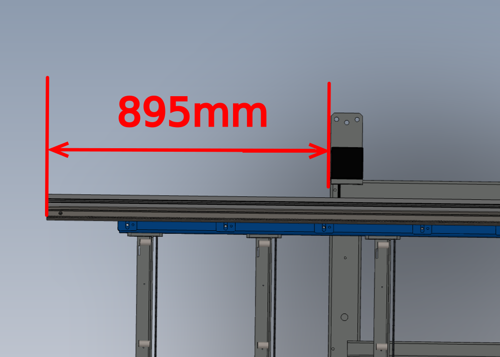
Étape 11 - Set beam position
Hepco slide rail should be positioned as drawing
Étape 12 - Assemble carriage
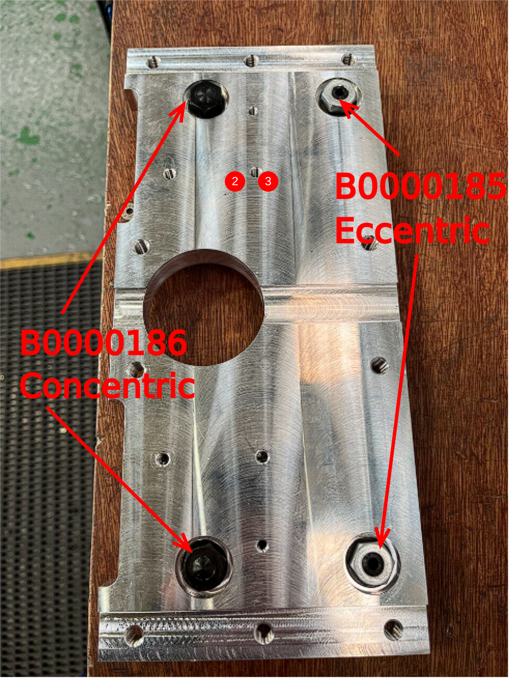
D0015072 Carriage Plate x 1
B0000185 Double Row Long Stud Journal Eccentric x 2
B0000186 Double Row Long Stud Journal Concentric x2
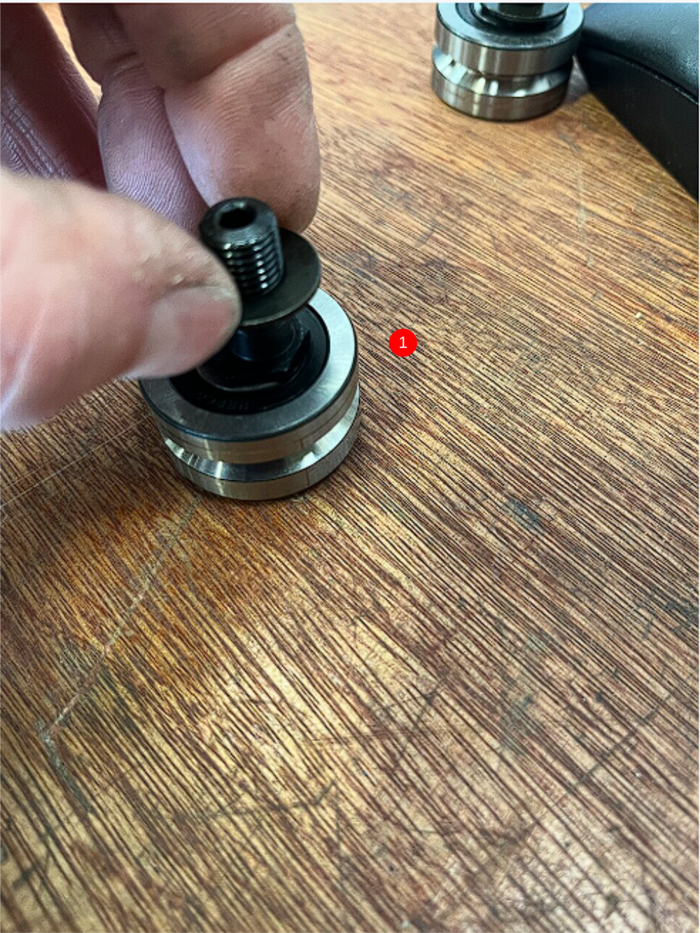
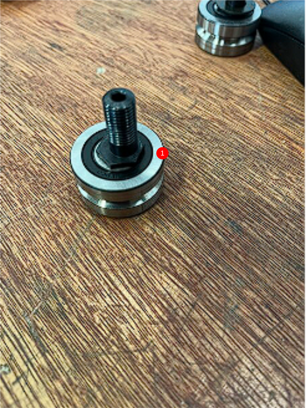
1 Remove nuts and washers from journals
2 Insert into carriage plate in positions shown
3 Add washer and nut to top face with no adhesive

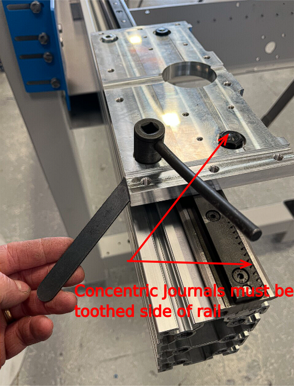
Étape 13 - Set journals
Fit assembled carriage plate to hepco slide ,orientated as shown
Set Tension on eccentric journals using hepco flat spanner and box wrench
Correct tension is
The journal setting must be checked at several points across the hepco rail .Journals should be adjusted to give the best contact overall along the entire travel of the carriage plate
Once correct setting has been achieved , Journal fixing nuts should be tensioned to 33nm using torque wrench

Étape 14 - Fit wipers and finalise
Remove carriage plate
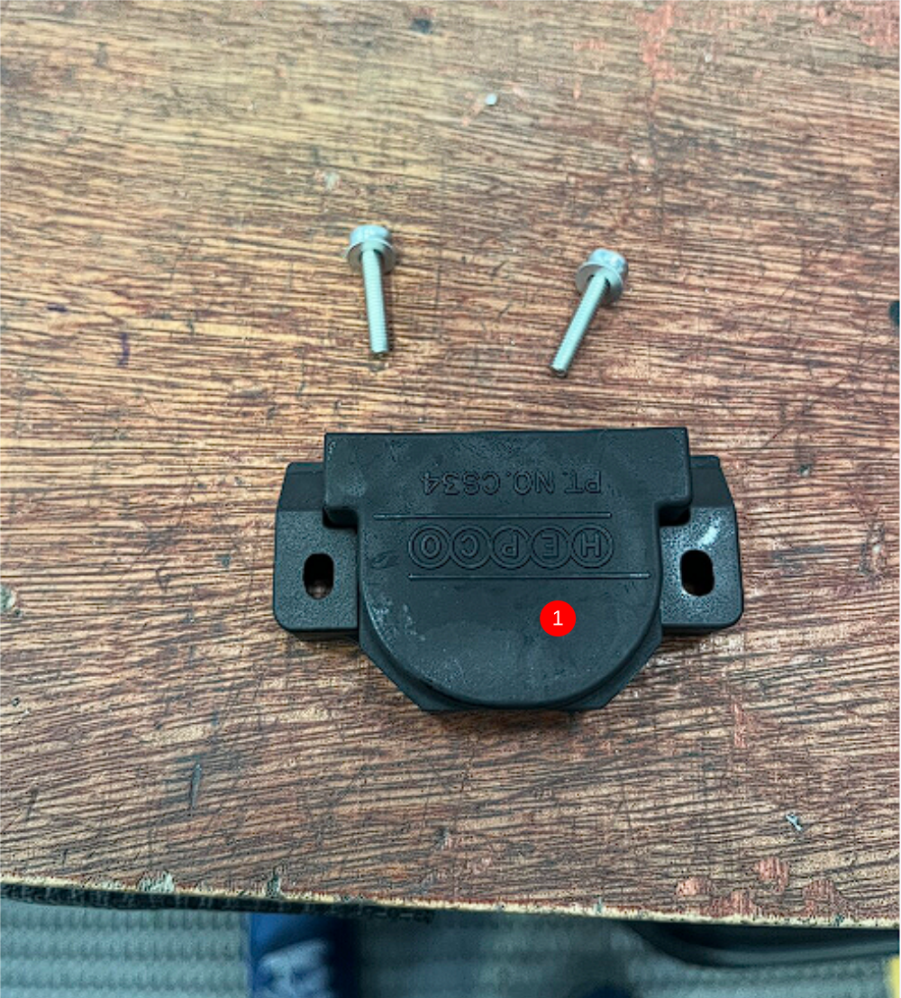
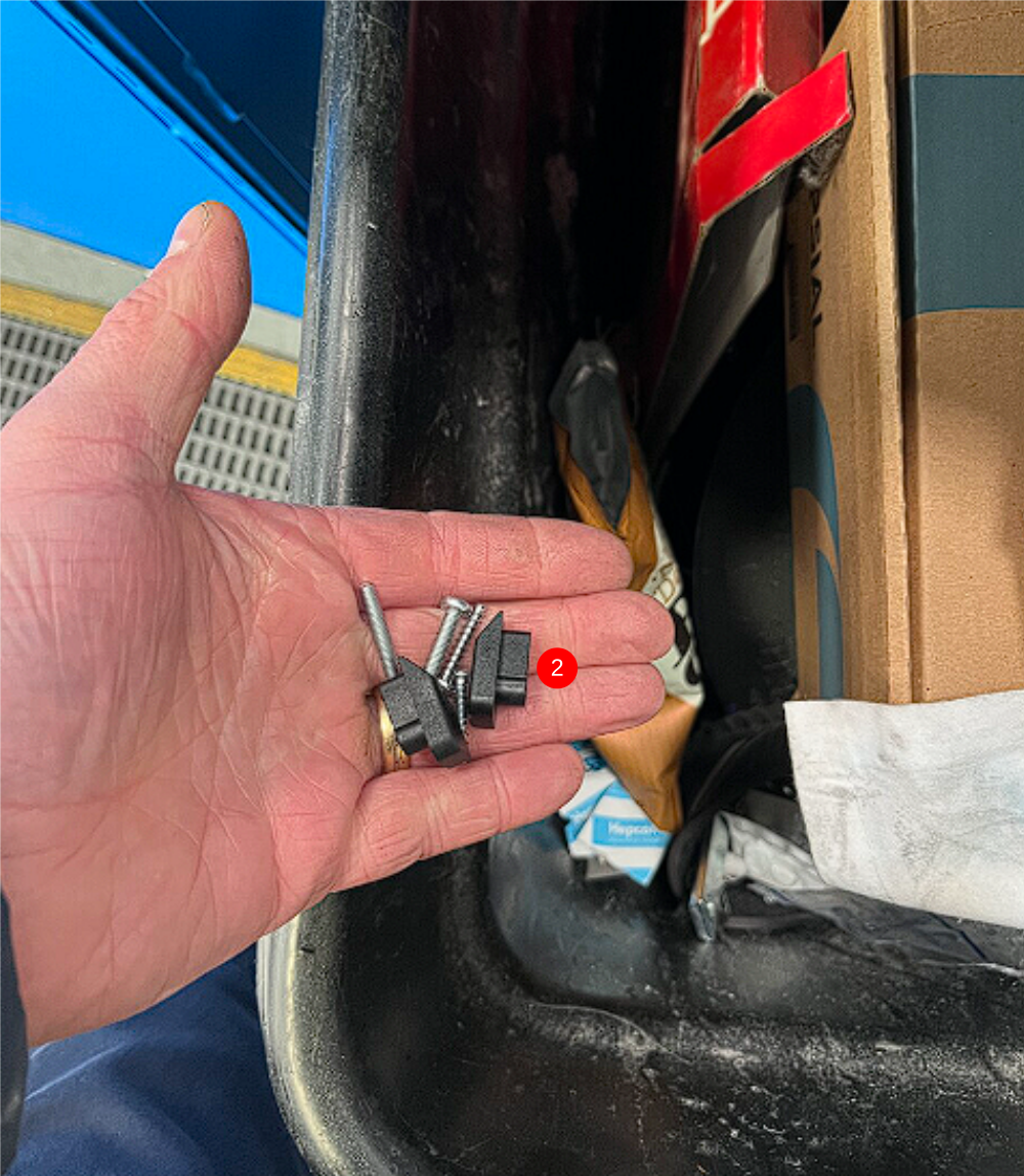
1 Fit B0000184 x 4 cap seals with adjustable inserts (supplied with cap) Adjust so journal is not in contact with cap seal but close as possible
Use 2 off M4 x 20 socket caps and M4 A Form washers per cap seal to fix
2 Dispose of fixed variant
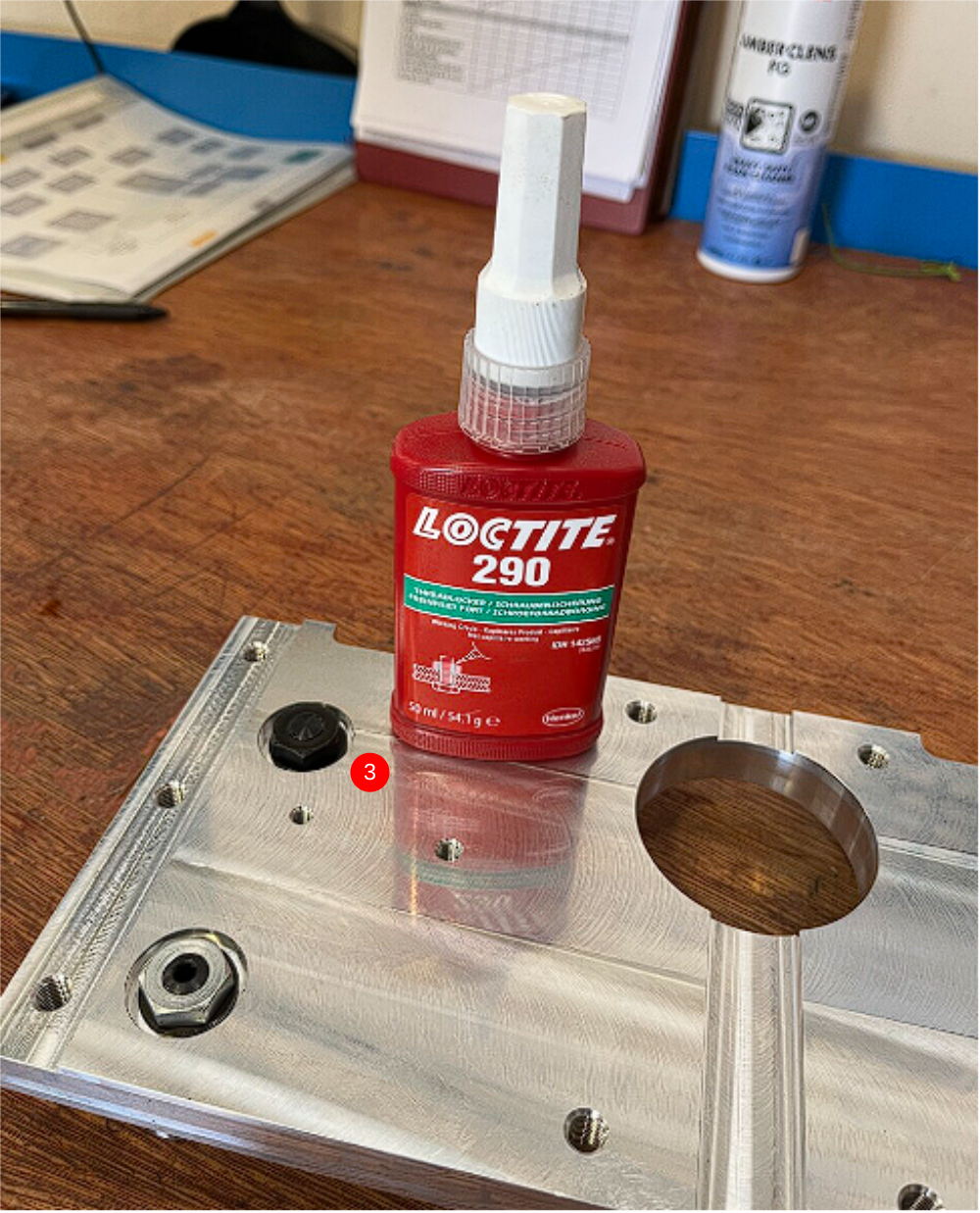
3 Add Loctite 290 to finalised journal nuts
Étape 15 - Refit carriage plate
Refit carriage plate to hepco rail and check travel along the entire length to confirm correct position of cap seals. If it has become hard to push cap seals are not positioned correctly
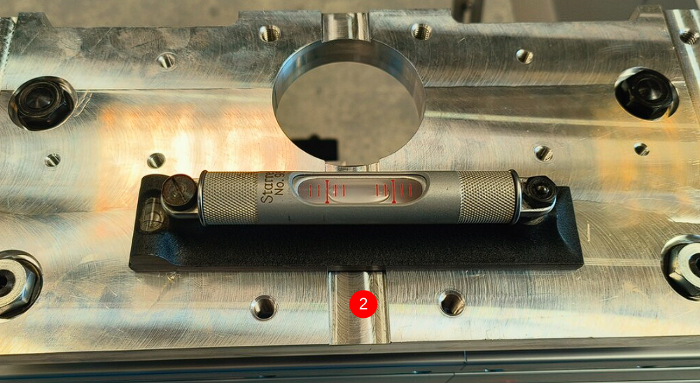
Étape 16 - Check level of carriage plate
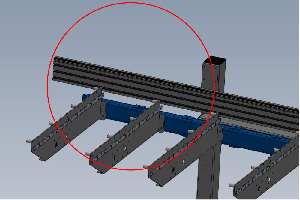
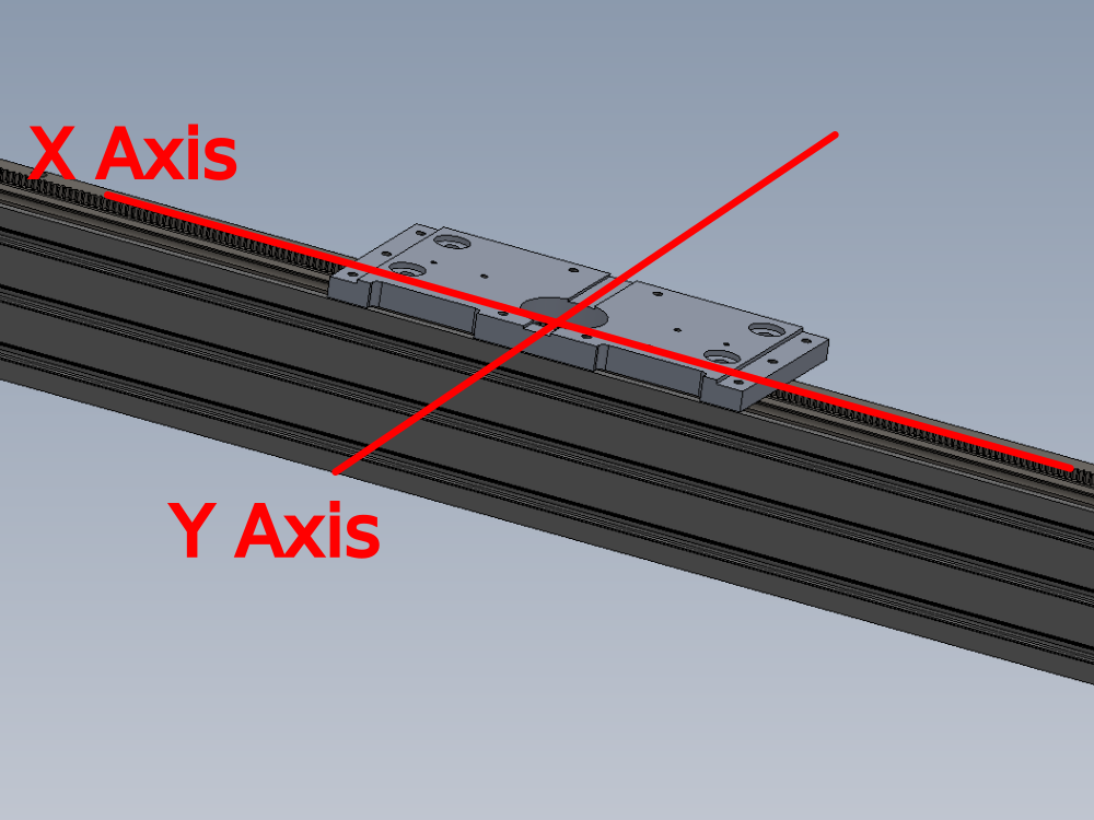
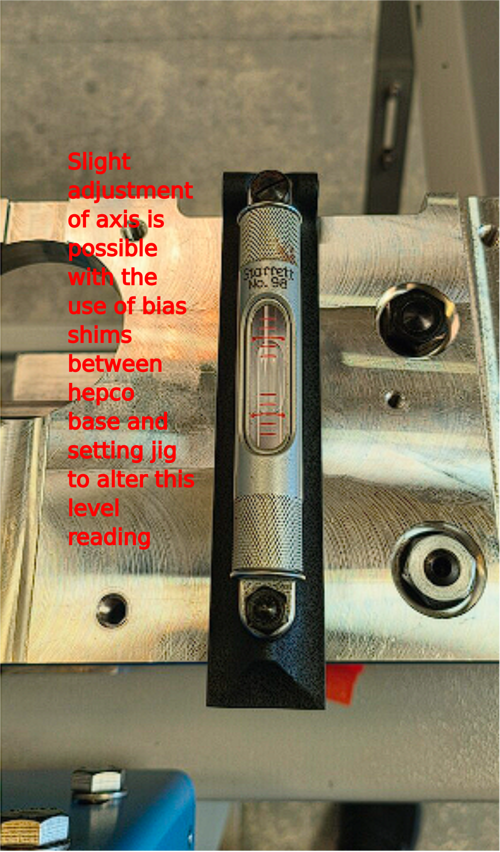
Inspect Level of hepco beam as shown . These levels should be checked at every 300mm along the entire length of the beam. This will give an indication of what is required for adjustment .


Étape 17 - 1st stage levelling
Tolerancing
X axis level -+ 2 divisions on engineers 300m level
Y axis level -+ 3 divisions on engineers 300mm level
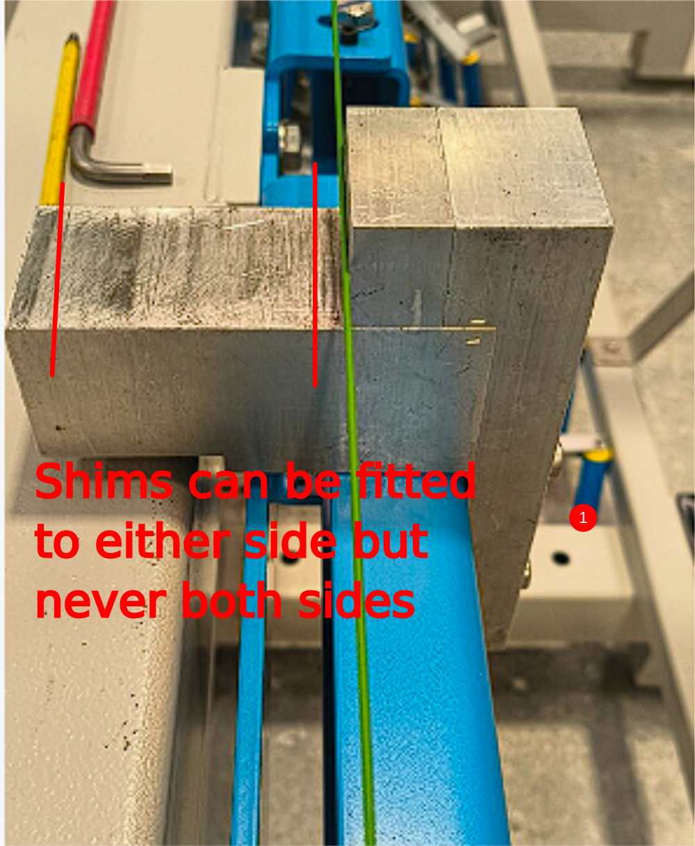
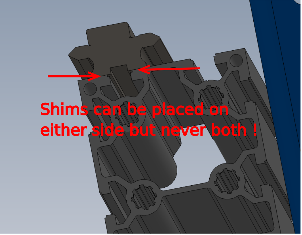
1 The first stage of levelling any discrepancy from the rail is to add bias shims to the setting jigs that the hepco rails is sitting on . This will only give slight adjustment in one direction . Image shows where shims can be added to adjust level indicated. Never add shims to both sides (hepco beam is removed for clarity of shim location )
2 Leveling in this direction is not likely, if setting jigs are set up correctly then this level will be correct
If this process corrects any discrepancies on level move to mounting bracket stage . If more adjustment is required continue to step 17
Étape 18 - 2nd stage leveling if required
In extreme cases additional adjustment may be required for correct positioning
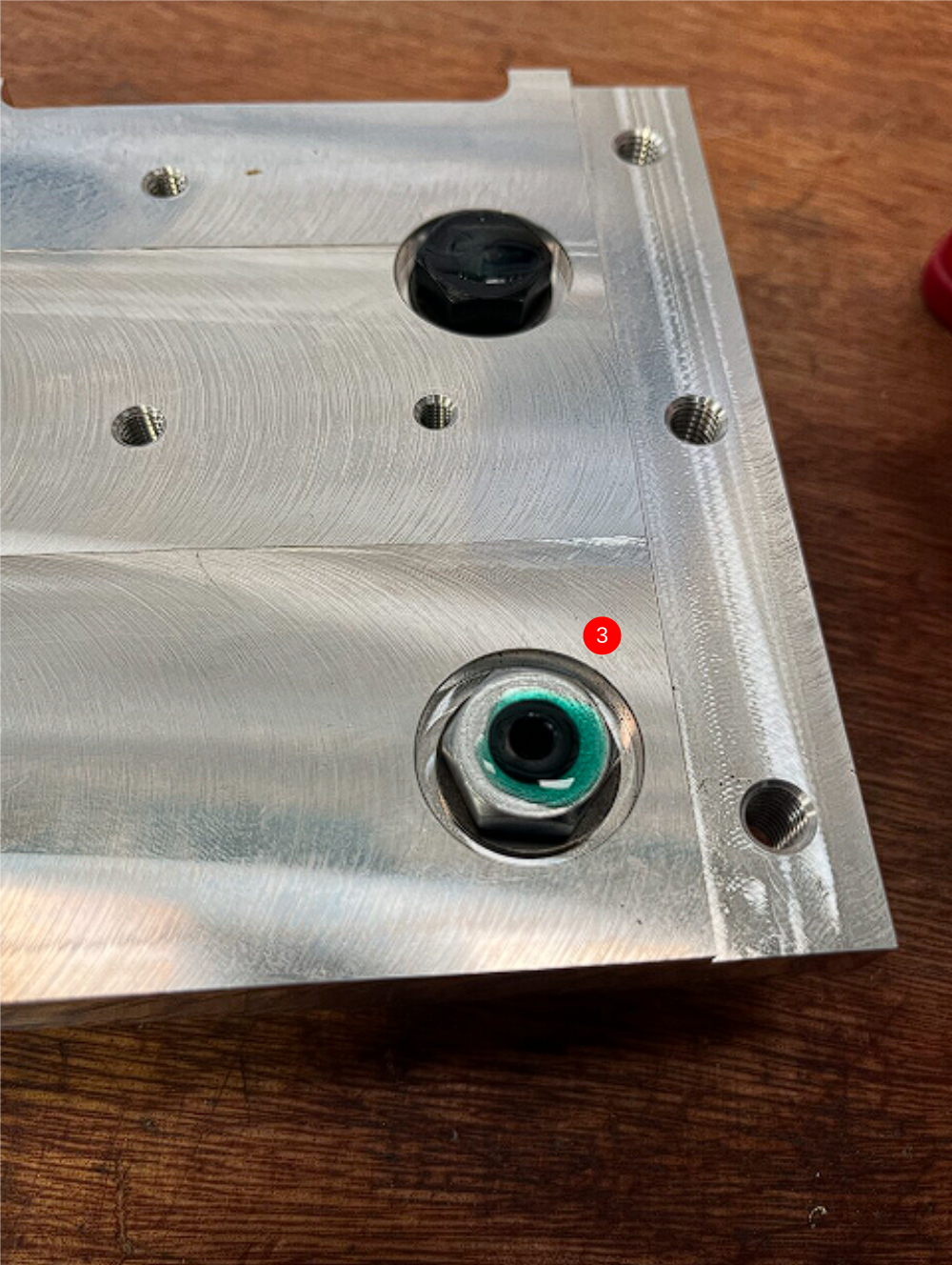
Shims can be placed between the main hepco slide and extruded mounting section. This step should only be undertaken with supervisor authorisation
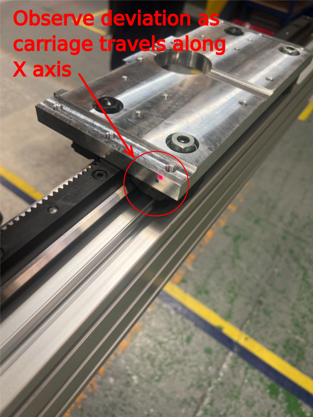
Étape 19 - Laser checks
Tolerance. -+ 6mm
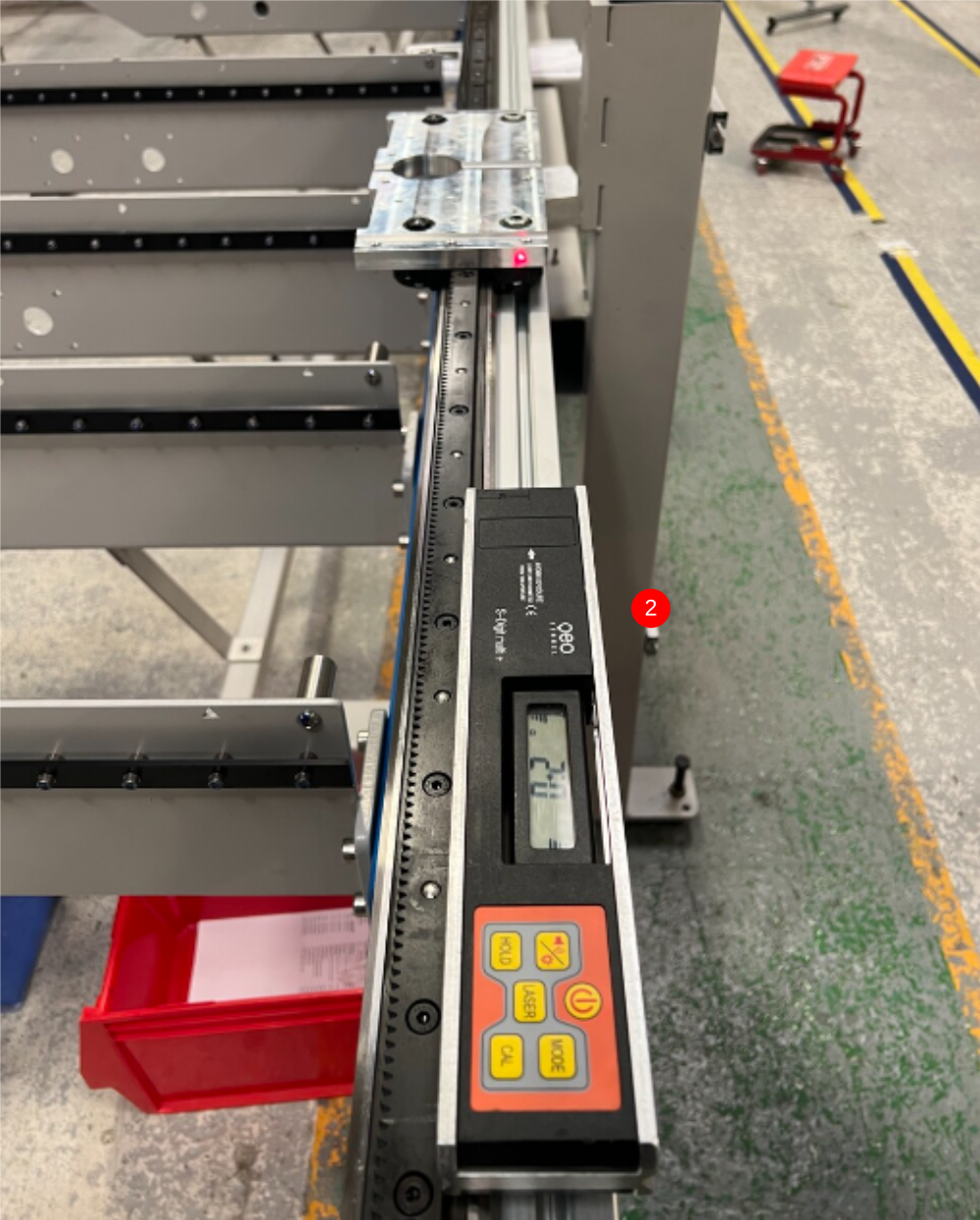
Once the hepco rail has been positioned and levelled correctly, a laser check must be performed to ensure straightness of hepco rail
1 Position laser as shown and move carriage to indicated area
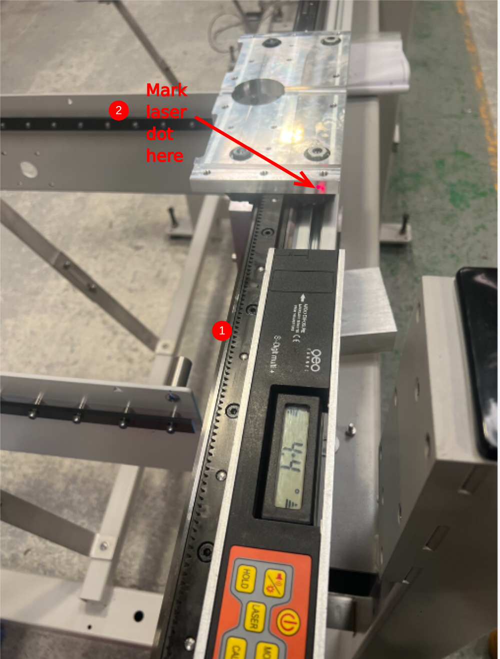
2 Mark laser dot onto carriage
3 Move carriage along entire length of hepco rail observing any deviation from marked point and laser dot
4 Report any deviation greater than 6mm
Draft
 Français
 English
 Deutsch
 Español
 Italiano
 Português