Instructions for mounting and aligning hepco x axis beam

Difficulté
Très difficile
Durée
8 heure(s)
Sommaire
- 1 Introduction
- 2 Étape 1 - Unless otherwise stated
- 3 Étape 2 - Additional spacer
- 4 Étape 3 - Attach Setting jigs
- 5 Étape 4 - Level Setting Jigs
- 6 Étape 5 - Level x axis between jigs
- 7 Étape 6 - Wire line for setting straightness
- 8 Étape 7 - Quality Check
- 9 Étape 8 - Position Hepco double edge slide
- 10 Étape 9 - Mechanically join Hepco beam
- 11 Étape 10 - Set beam position
- 12 Étape 11 -
- 13 Étape 12 -
- 14 Commentaires
Introduction
Tools Required
Engineers level
Hepco flat spanner
Hepco Box spanner
Standard hex key set
Incremental shim pack
Parts Required
B0000046 Slide Base Bearing Block (Straight Grease Nipple) x 6
B0000184 Journal Cap Seal 34 x 4
B0000185 Double Row Long Stud Journal Eccentric x 2
B0000186 Double Row Long Stud Journal Concentric x 2
B0000234 Straight Grease Nipple M6 ST/ST x 6
B0001006 Linear rail 25mm x 820mm x 6
B0001102 Double edge spacer slide and beam 7600mm x 1
D0015072 Carriage Plate x 1
D0015492 Vertical Beam Adjustment Plate x 5
D0015493 Lateral Beam Adjustment Plate x 5
P0000200 Elbow Adaptor 6mm - M5 x 1Étape 1 - Unless otherwise stated
Use Loctite 243 on all fasteners
Use Loctite 570 on all threaded pneumatic connections
Pen mark all bolts once finalised

Étape 2 - Additional spacer
Ensure additional spacer is removed from jigs when using for alignment on module C
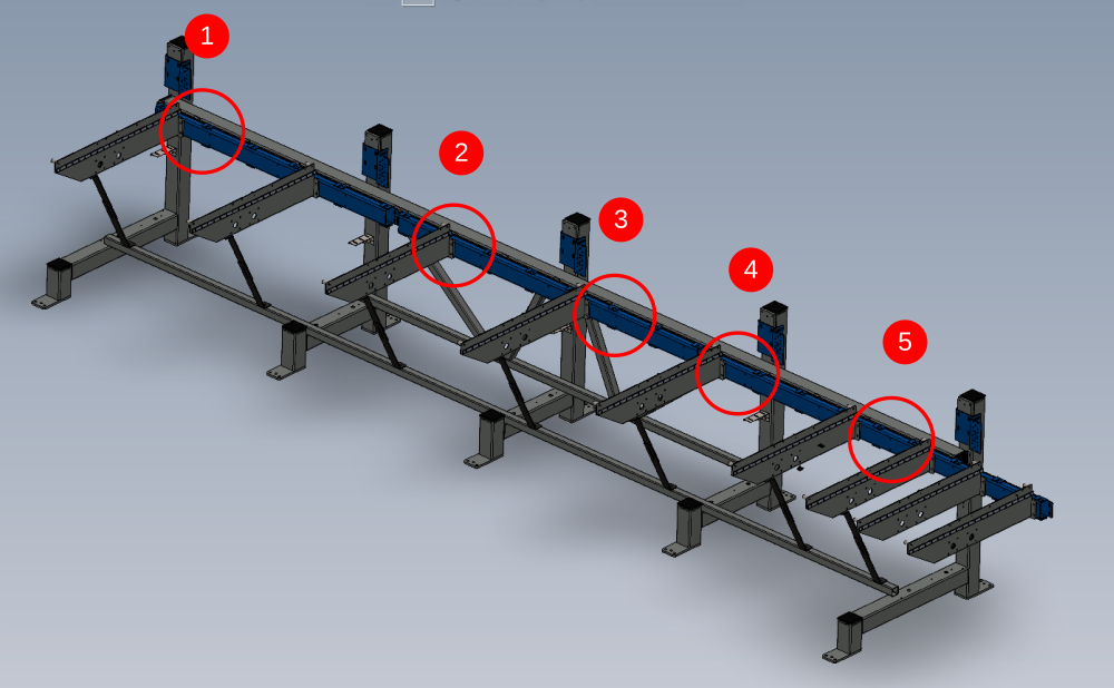
Étape 3 - Attach Setting jigs
Mount setting jigs to channel section in positions shown using M8 cap head bolts and heavy washers
Position one shown will require fixing points drilling to channel section . Drill M8 and position to measurement shown of 430mm

Étape 4 - Level Setting Jigs
Use an engineers level to individually adjust each jig to be level on both axis


Étape 5 - Level x axis between jigs
Using a 2 meter straight edge , the jigs should be levelled to each other as shown.
Identify which Jig is the lowest point by using the straight edge and level . Adjust the lower height jigs to match the highest point one. This is to ensure that the height is maintained as much as possible between blue mounting bar and jig top face
When a jig is adjusted for height, i will need rechecking to see if the other previous levelled plains have moved. If so, re adjust to bring jig level in all axis


Étape 6 - Wire line for setting straightness
A wire line should be used for setting the straightness of the jigs along the x axis
Use dokit Alignment guide using wire line for correct process to set up


Étape 7 - Quality Check
Qc Double check required at this point from Supervisor that all alignment is correct.

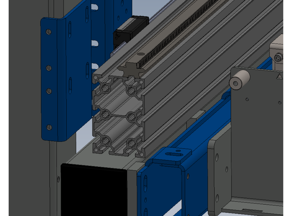
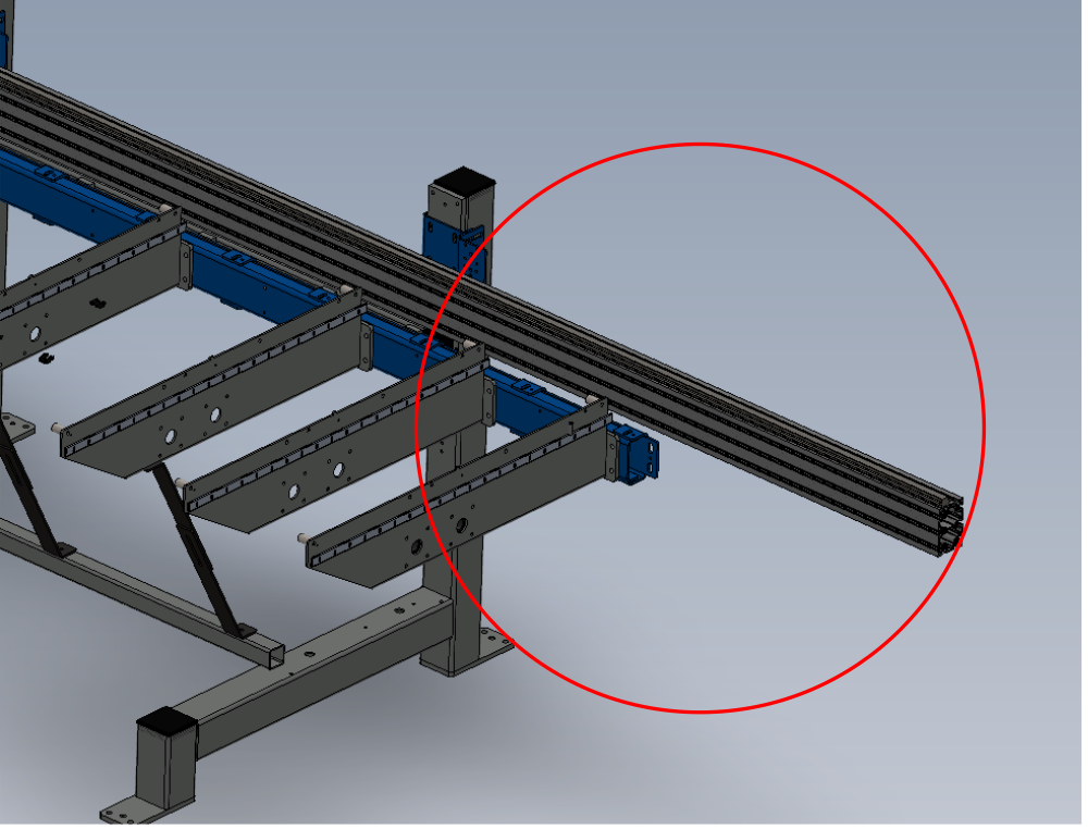
Étape 8 - Position Hepco double edge slide
B0001102 can now be assembled on jigs .
These beams are paired so check you have been issued a set correctly
Pairs can be identified as follows
1 and 1
2 and 2
A and A
B and B


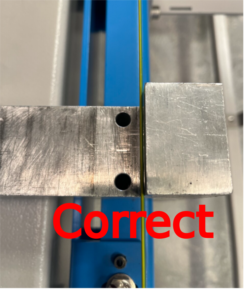
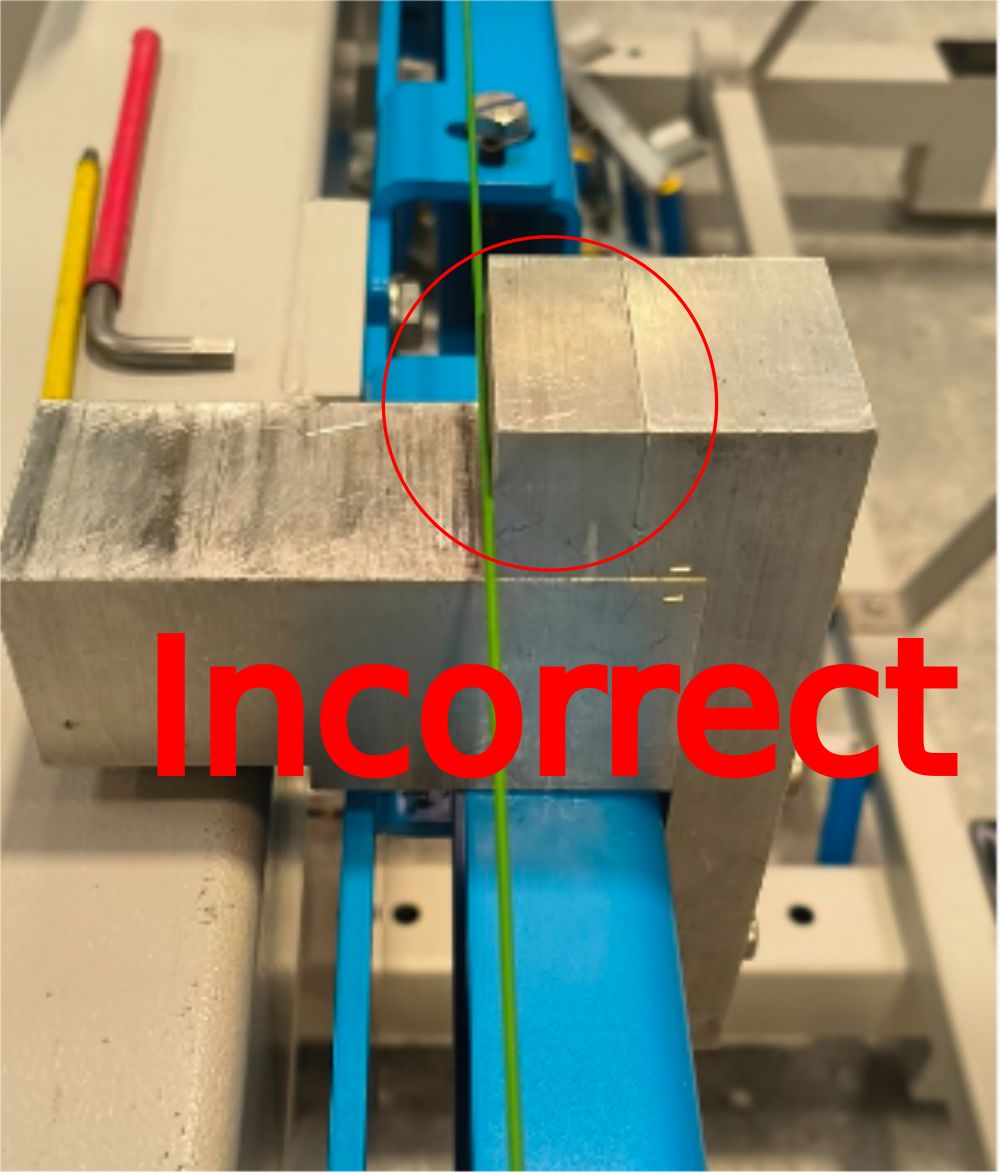
Étape 9 - Mechanically join Hepco beam
1 Use jig shown to ensure correct pitching of 2 sections of drive rail when coupled together
2 Use v blocks to ensure alignment of V's on hepco rail are correct when mating the two parts
3 Position and tighten the joining bars between the two sections (picture required)


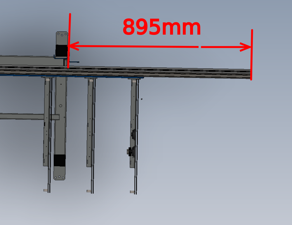
Étape 10 - Set beam position
Hepco slide rail should be positioned as drawing
Étape 11 -
Étape 12 -
Draft
 Français
 English
 Deutsch
 Español
 Italiano
 Português