Instructions to bench assemble gripper


Difficulté
Moyen
Durée
2 heure(s)
Sommaire
- 1 Introduction
- 2 Étape 1 - Unless otherwise stated
- 3 Étape 2 - Fit bushes and bearings
- 4 Étape 3 - check fitment of D0015084 shafts
- 5 Étape 4 - Assemble load switch plate
- 6 Étape 5 - Assemble cylinder P0001120
- 7 Étape 6 - Assemble grip pin assembly
- 8 Étape 7 - Mount grip pin assembly to grip slide
- 9 Étape 8 - Assemble main frame of gripper assembly
- 10 Étape 9 - Fit link bars to assembly
- 11 Étape 10 - Fit Cylinder assembly
- 12 Étape 11 - Add mounting brackets
- 13 Commentaires
Introduction
Tools Required
Étape 1 - Unless otherwise stated
Use Loctite 243 on all fasteners
Pen mark all bolts once finalised

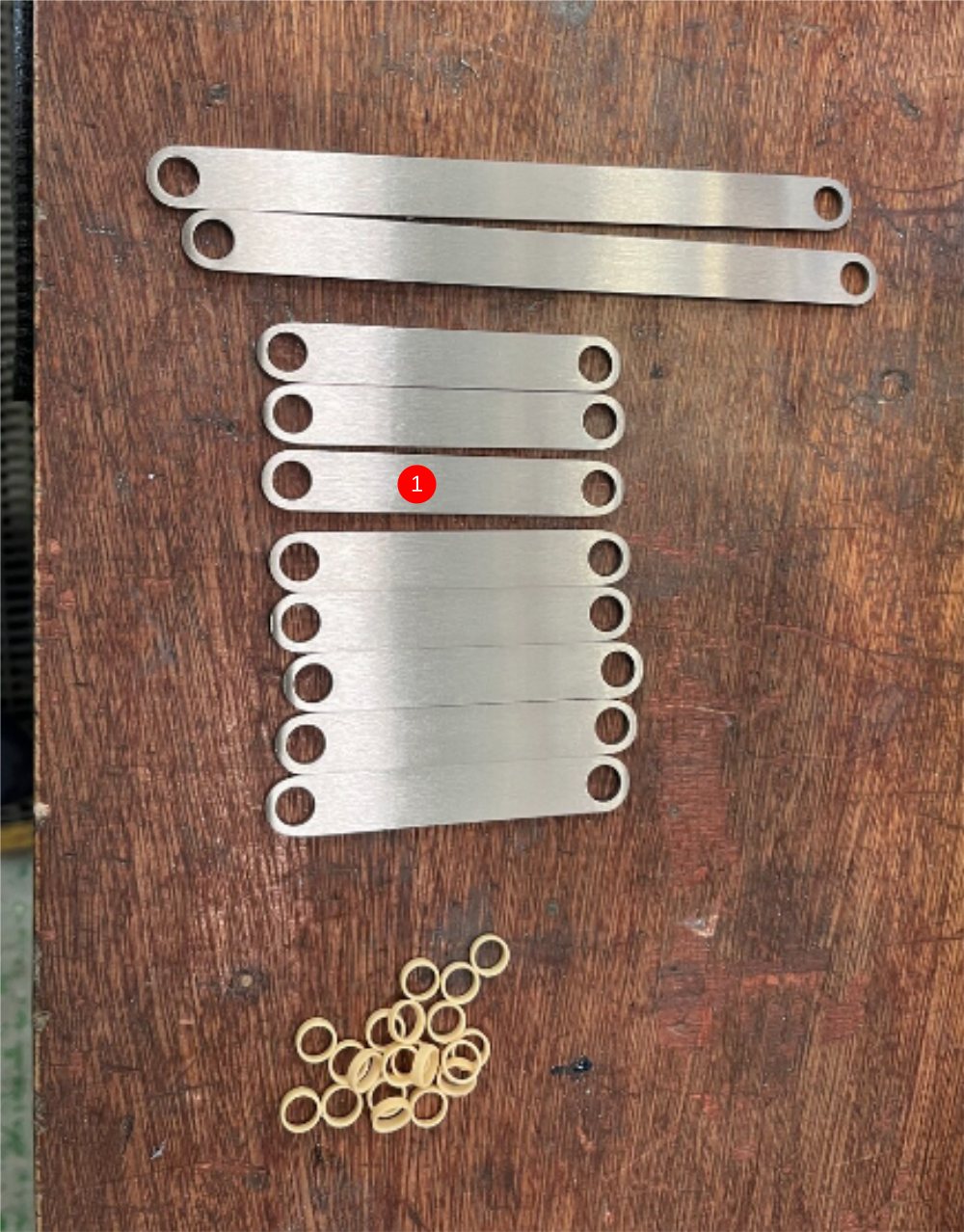
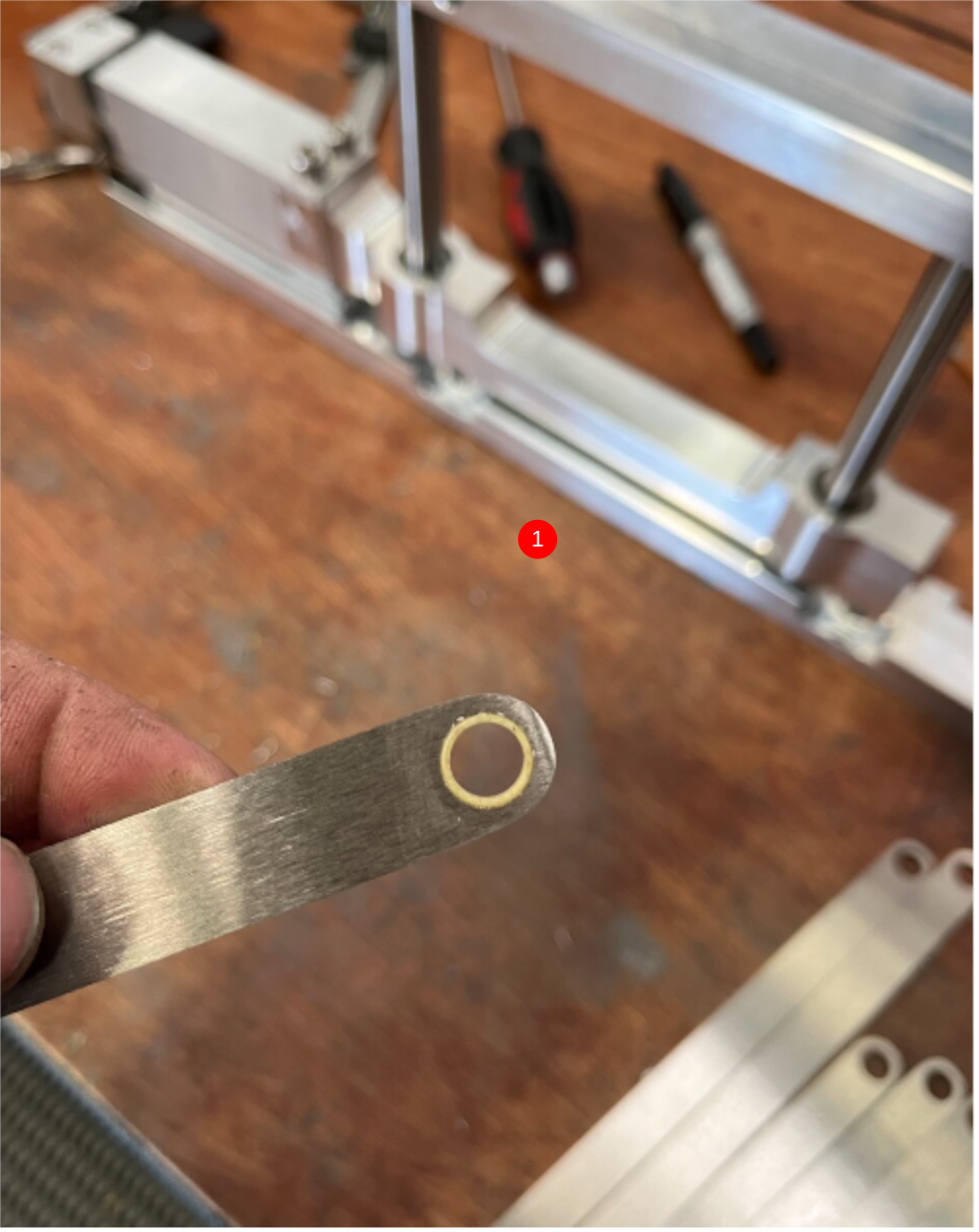
Étape 2 - Fit bushes and bearings
1 Fit bushes B0001106 (20 off) to
8 off D0015095 link bars
2 off D0015096 link bars
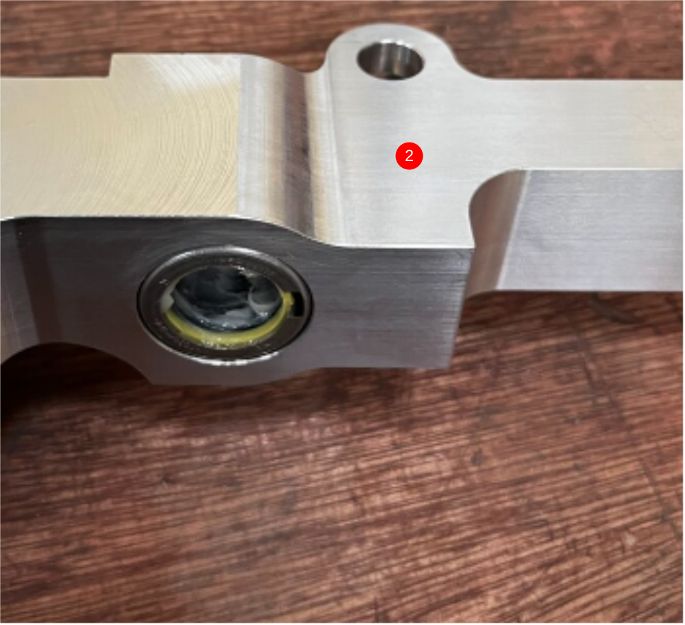
2 Fit bearings B0000034 x 2 into D00015086 grip slide body. Use grease to lubricate bearing before assembly
Étape 3 - check fitment of D0015084 shafts
Check shafts fit correctly into bores of D0015082 gripper bottom bar and D0015083 gripper upper bar

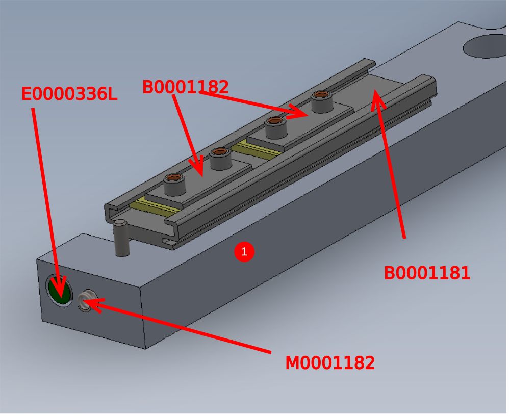
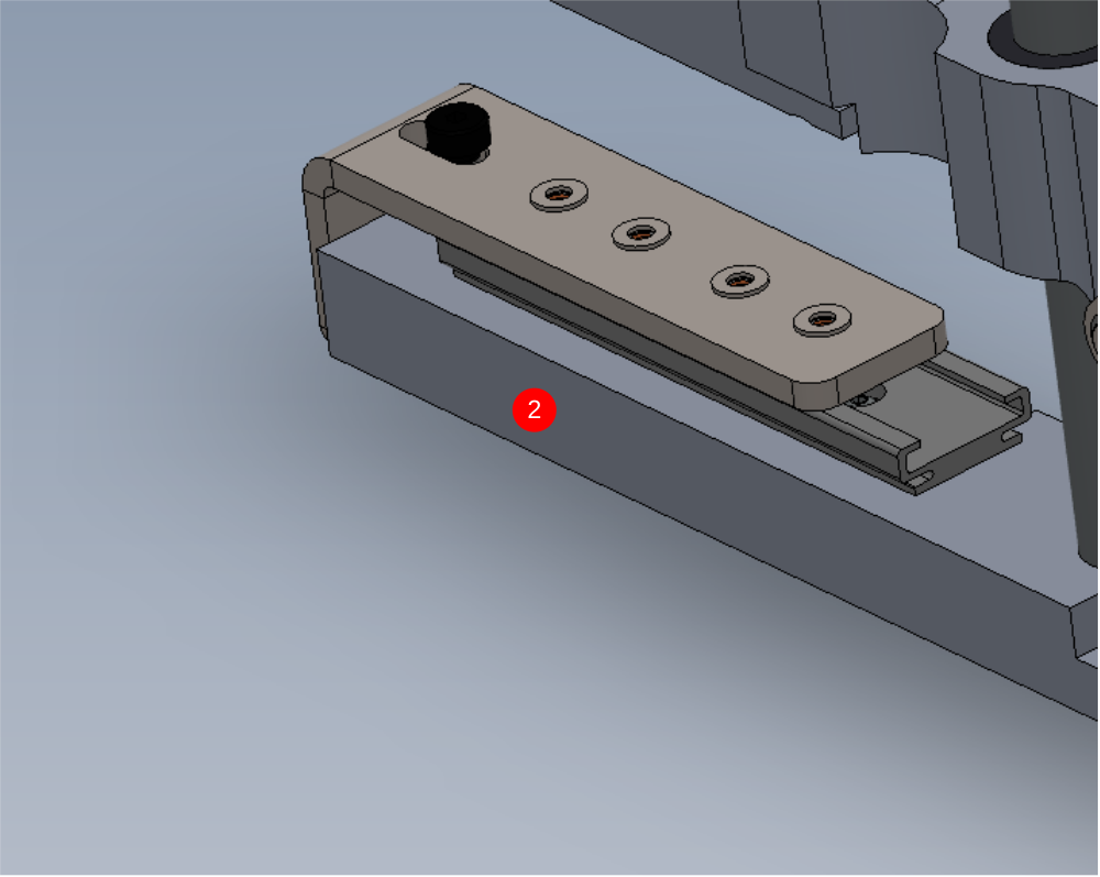
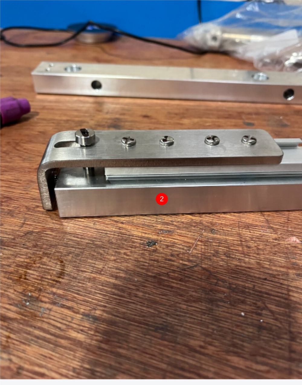
Étape 4 - Assemble load switch plate
1 Use M4 x 6 panhead to attach B0001181 rail to gripper base
Fit E0000336L sensor and M0001182 spring to main base
2 Use M5x 6 x 16 shoulder bolt and M4 x 6 pan heads to attach D0015756 lever to assembly
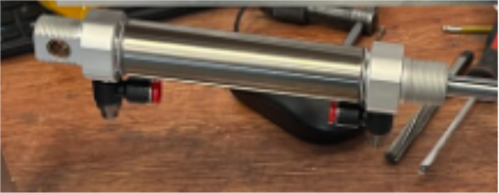
Étape 5 - Assemble cylinder P0001120
Fit air fitting P0001198 to cylinder
Remove 32mm nut from cylinder and discardd
Mount reed switch and band (P0001041 x 1 P0001047 x 1 P0001128 x 1) to cylinder in piston retracted position , mark as X283
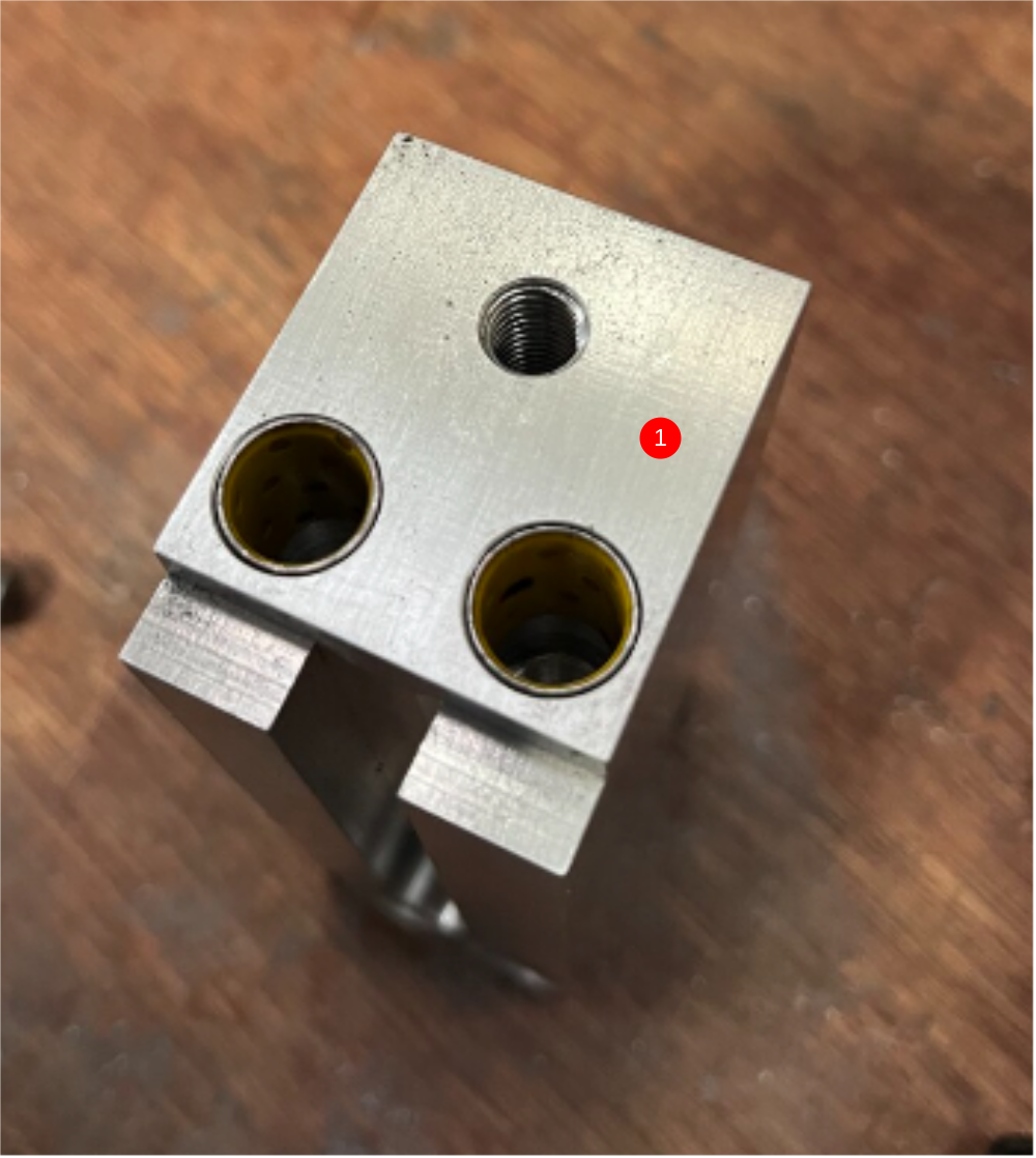
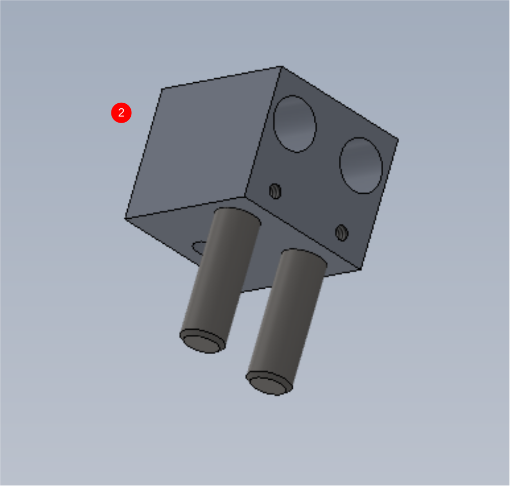
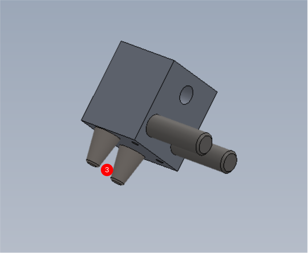
Étape 6 - Assemble grip pin assembly
1 Fit bushes B0000437 x2 to body D0015431
2 Use 2 off 10mm x 40mm dowel. Ensure dowels fit correctly in nose D0015430. Check dowels have pushed all the way to the bottom of the bore . Secure with 2 off M4 x 8 grubscrew
3 Fit D0015090 Grip pin x 2 and secure with M5x 16 socket cap
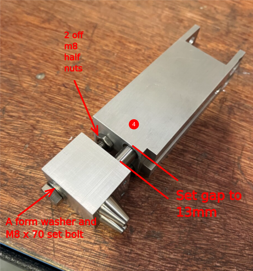
4 Combine together and use m8 x 70 set bolt, a form washer and 2 x m8 half nuts to secure. Set gap to 13mm and lock all fasteners
Correct gap set by set bolt and half nuts
correct length of bolt ?
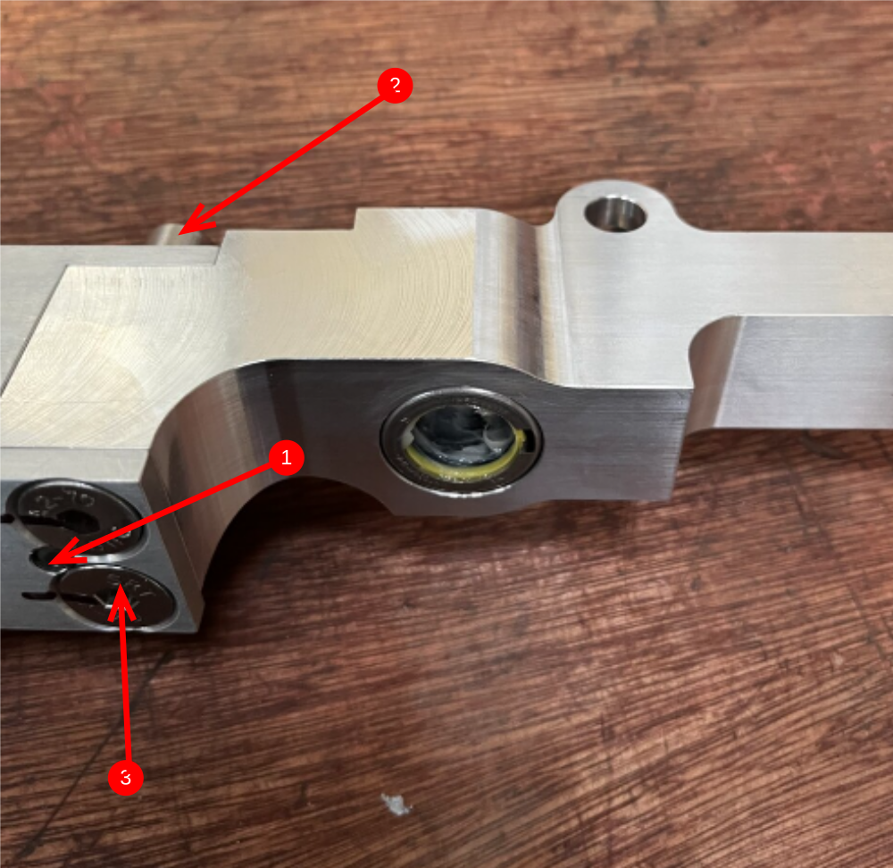
Étape 7 - Mount grip pin assembly to grip slide
Combine parts
1 Use 2 off 6mm x 16mm dowels to align ( 1 top and 1 bottom)
2 M8 x 16 socket cap and A form washer
3 M8 x 20 countersink


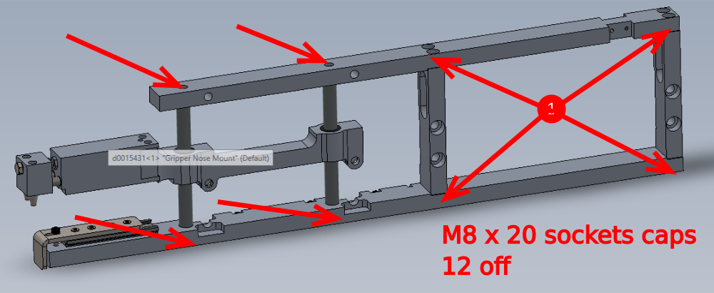
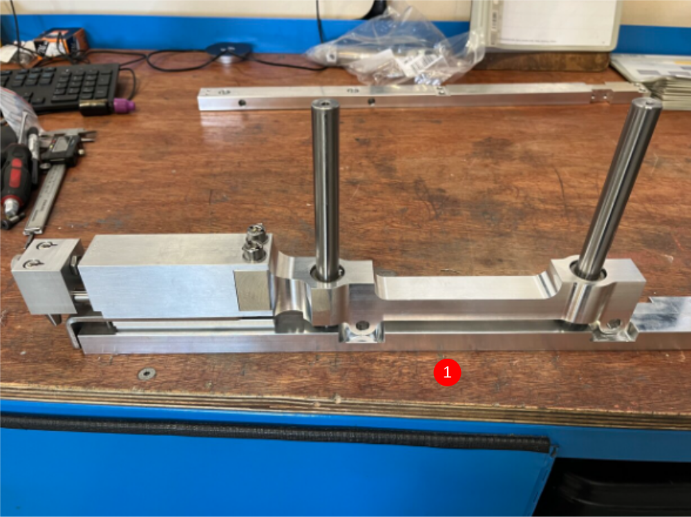
Étape 8 - Assemble main frame of gripper assembly
Use 2 off D0015085
1 Assemble as shown using 12 off M8 x 20 socket caps
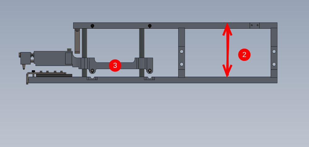
2 Check top and bottom bars are parallel
3 Check grip slide moves freely up and down
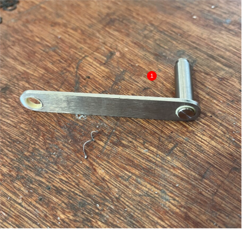
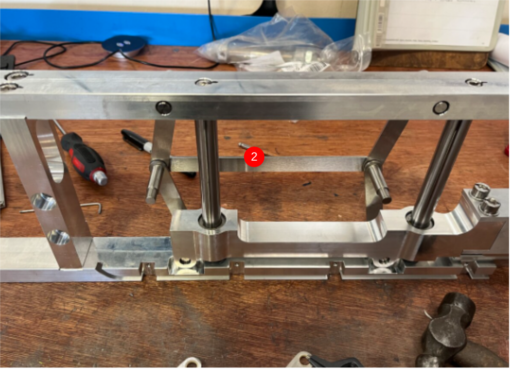
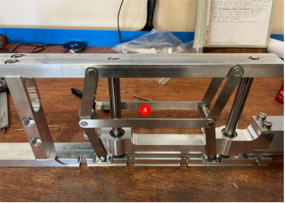
Étape 9 - Fit link bars to assembly
1 Use 2 off D0015103 and 8mm external circlips (B0000200) and assemble two off as shown
2 Use 2 off D0015102, 2 off D0015104 and assemble as shown with 8mm circlips
3 Use 2 off D0015170 gripper spacers and P0000049 spherical end and add as shown
4 Add remaining link shafts and circlips


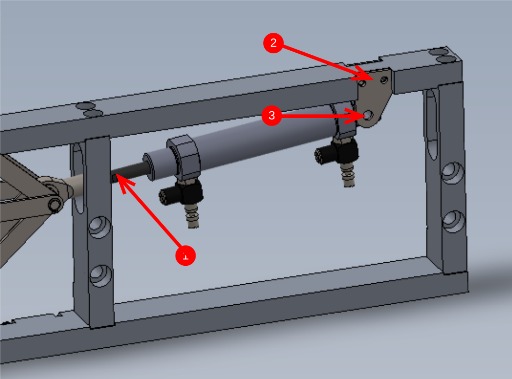
Étape 10 - Fit Cylinder assembly
Fit assembled cylinder unit to gripper frame
1 Wind cylinder thread into spherical bearing lock cylinder nut off with 1 thread of cylinder piston exposed behind lock nut
2 Use M5 x 10 with a form washer to secure D0015097 2 off mounting plates
3 Use M8 x 30 with M8 nyloc nut to secure cylinder to brackets
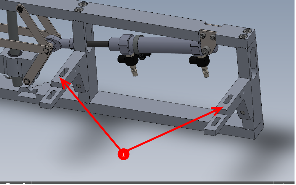
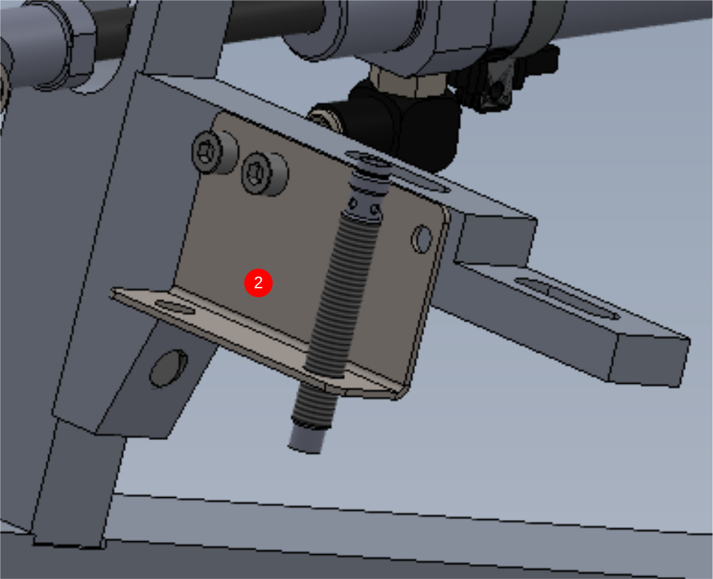
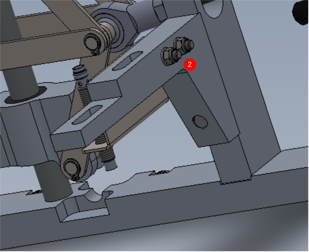
Étape 11 - Add mounting brackets
1 Fix as shown 2 off D0015100 brackets with 4 off M10 x 40 socket caps
2 Mount Sensor bracket D0015292 with 2 off M5 x 30 socket caps, A form washers and M5 Nyloc nuts. Mount E0000336 as shown using both lock nuts and shake proof washers provided with sensor
Draft
 Français
 English
 Deutsch
 Español
 Italiano
 Português