2nd stage of assembly of spindle assemblies


Difficulté
Moyen
Durée
2 heure(s)
Étape 1 - Mount single plunge spindle cylinder 2,4,6 and 8
Do not add final tension to bolts until alignment has been achieved
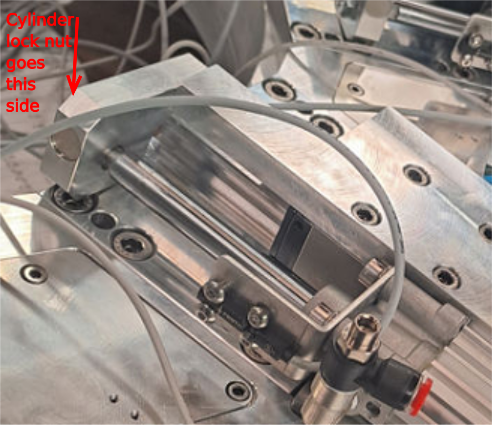
1 Attach pre built cylinder anchor to end of cylinder
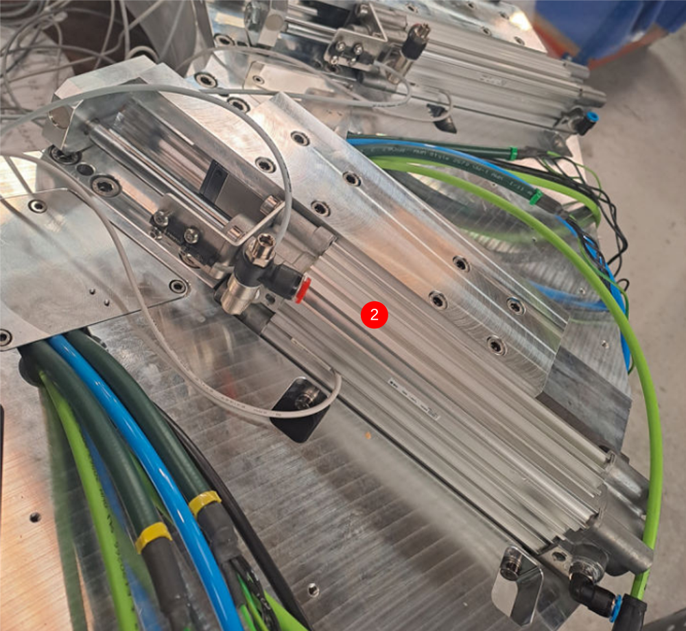
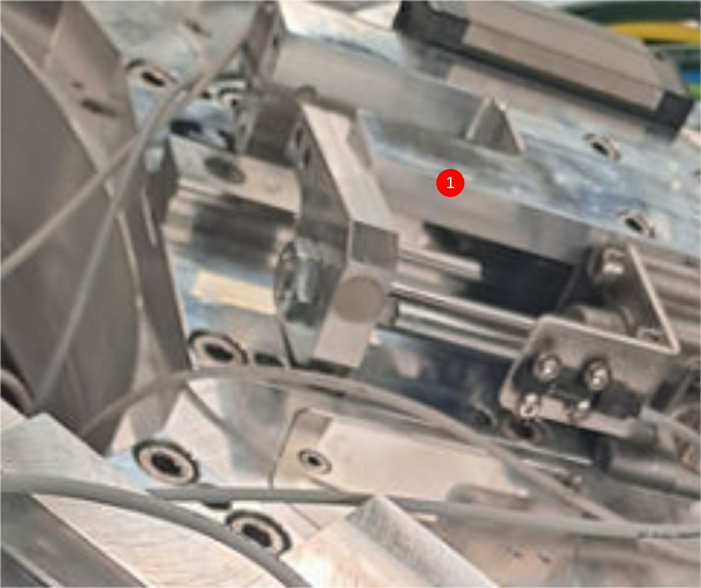
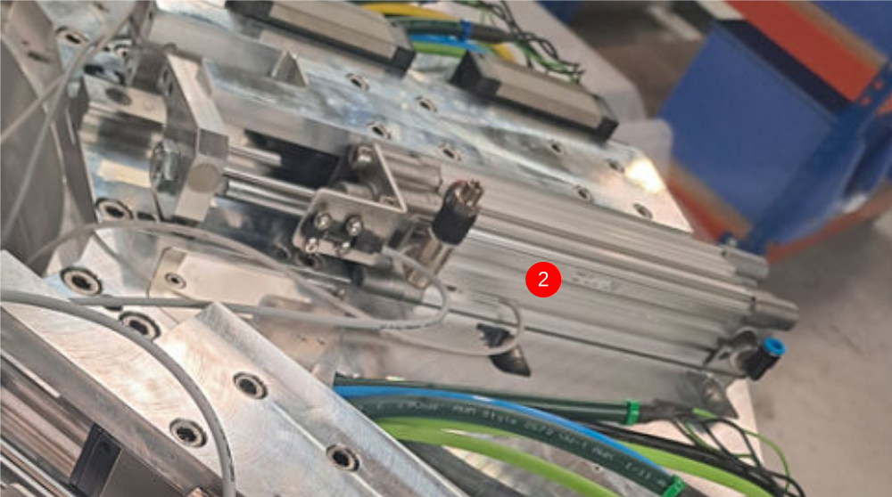
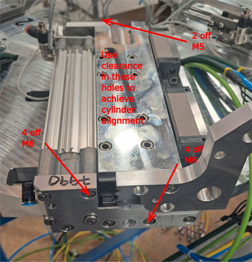
2 Position pre built cylinder on slide base assembly as shown
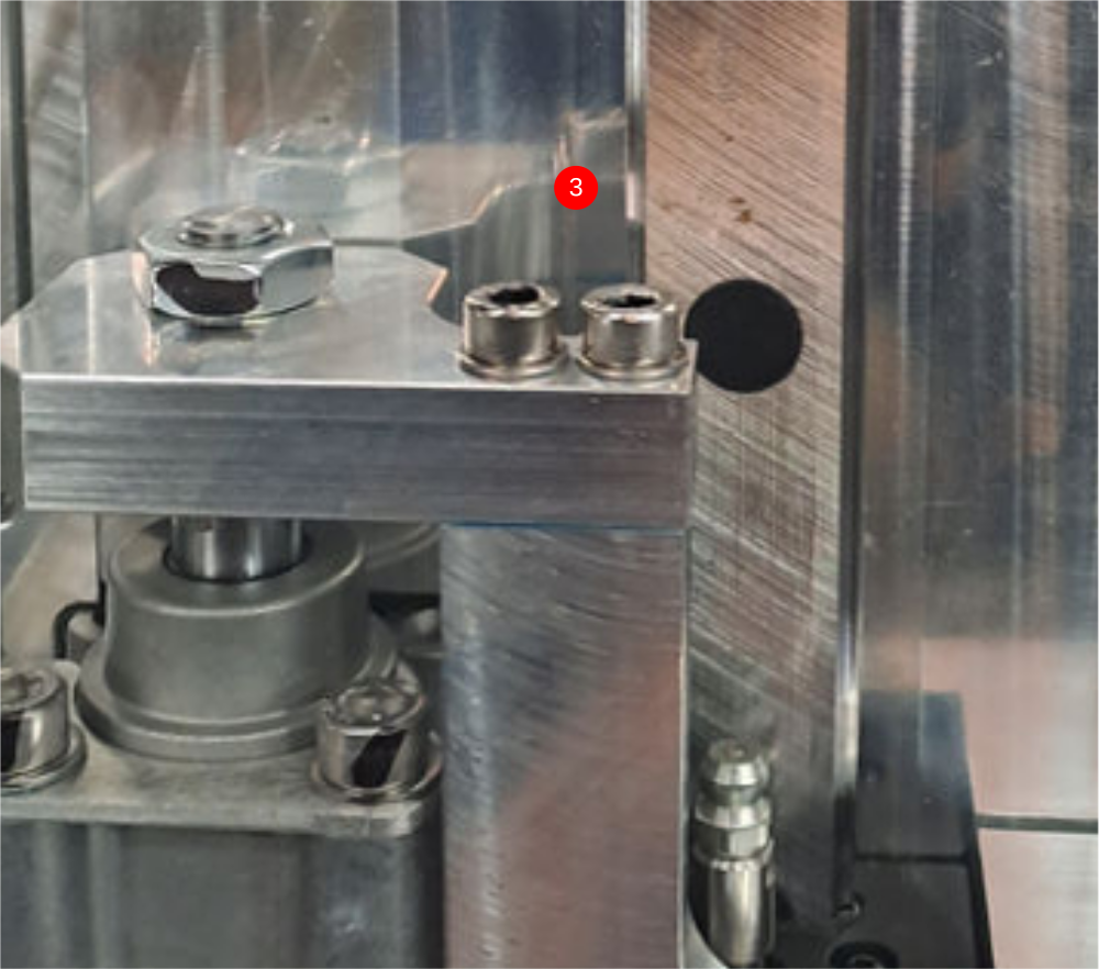
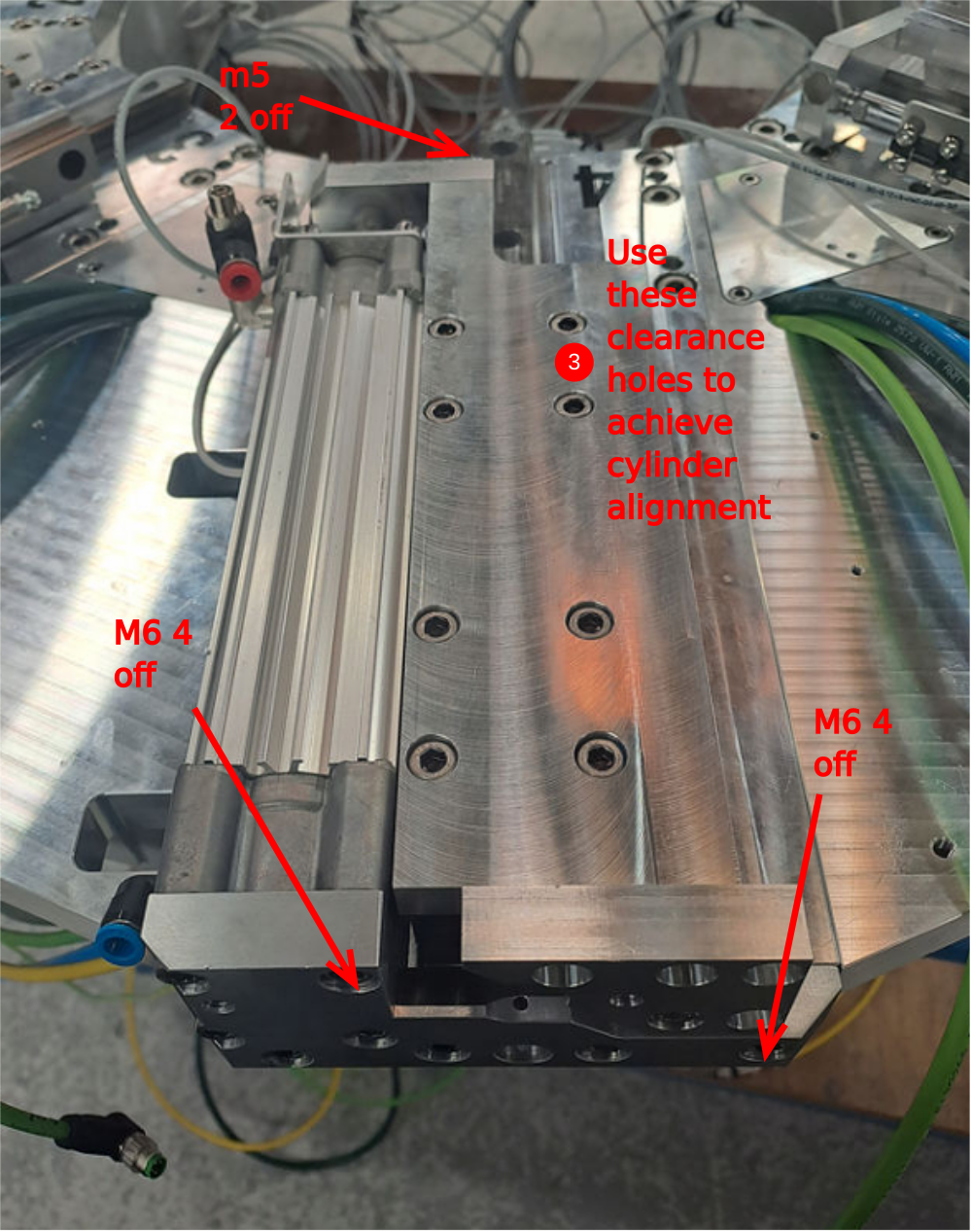
3 Use 2 off m5 x 25 socket caps with A form washers to attach to slide base
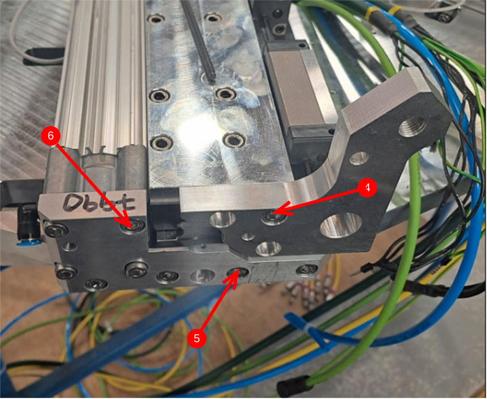
4 Temporarily mount D0007648 with 1 off m6 x 20 socket cap
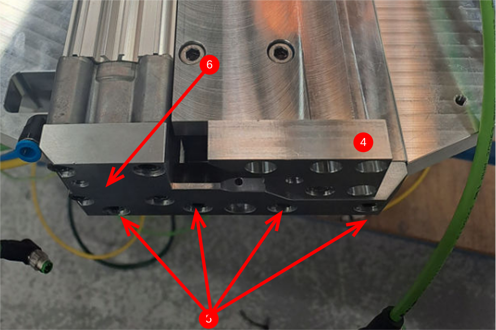
5 Attach D0007790 cylinder anchor with 4 off M6 x 20 socket caps
6 Attach Cylinder base to anchor with 4 off M6x 20 socket caps
Étape 2 - Align components and set position
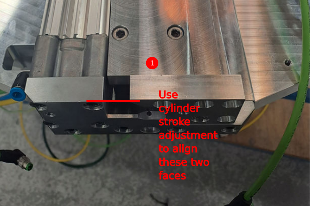
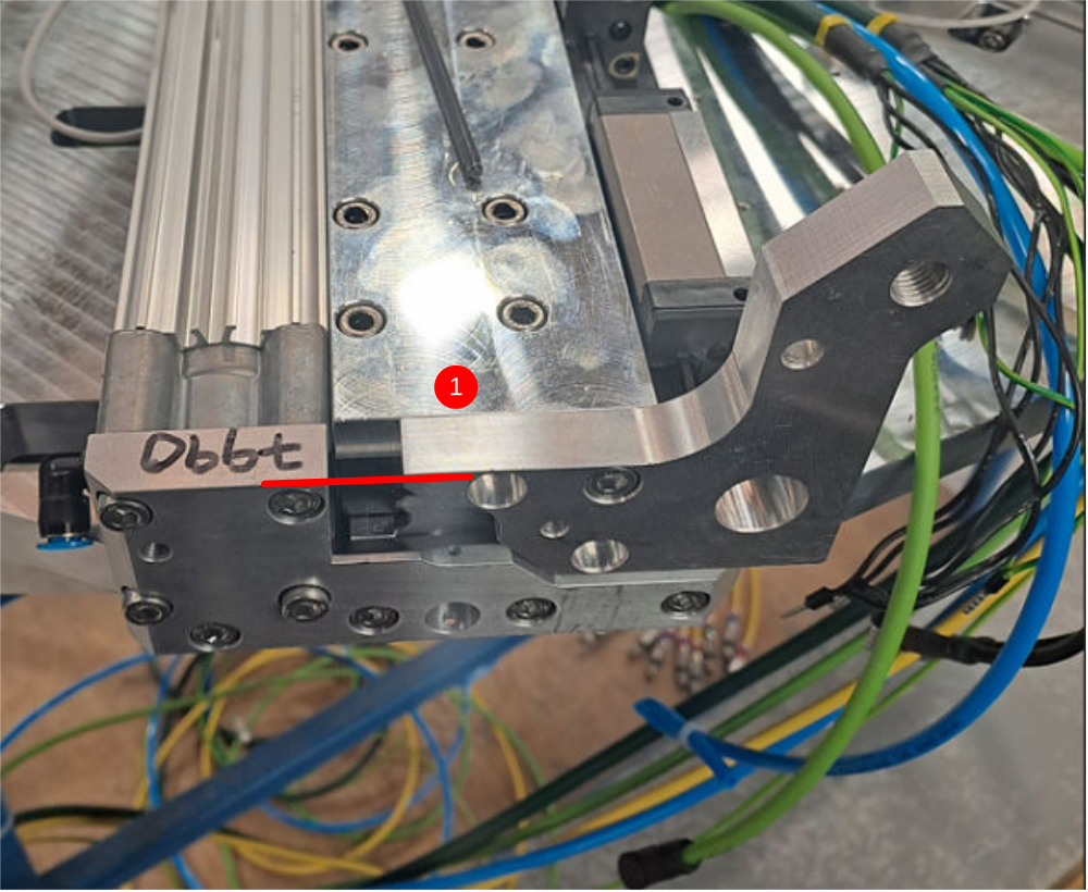
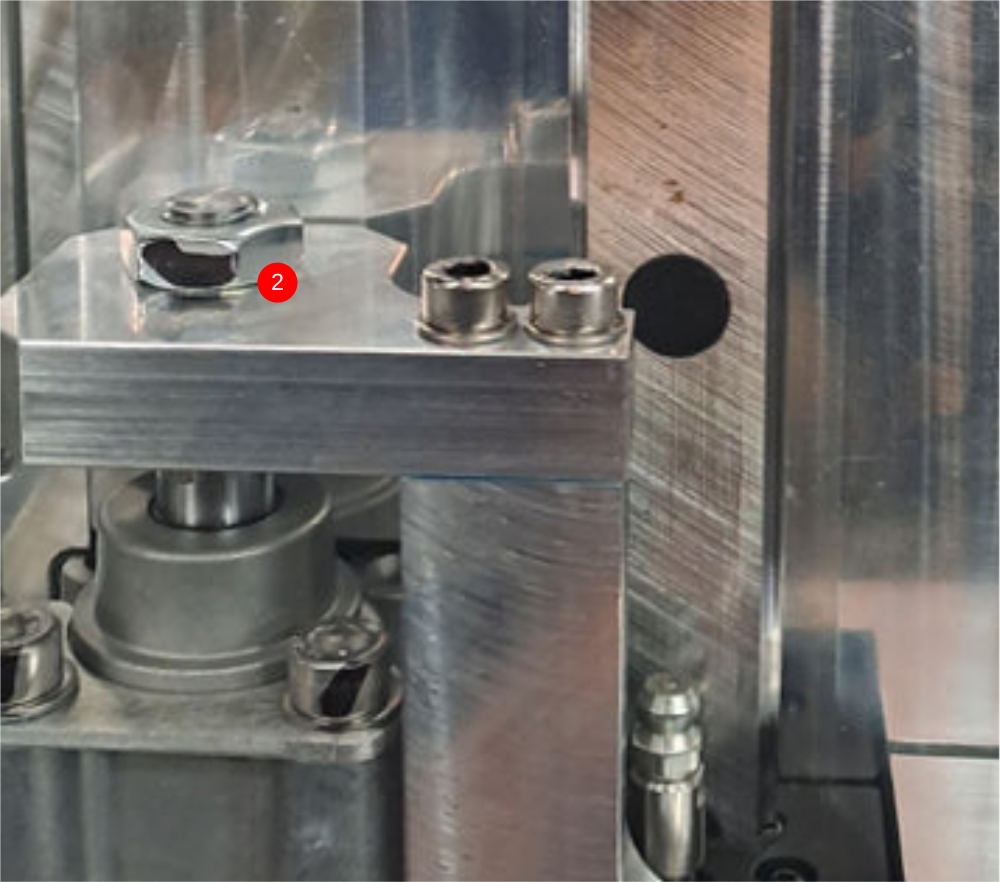
1 Use cylinder stroke adjustment to align these two faces
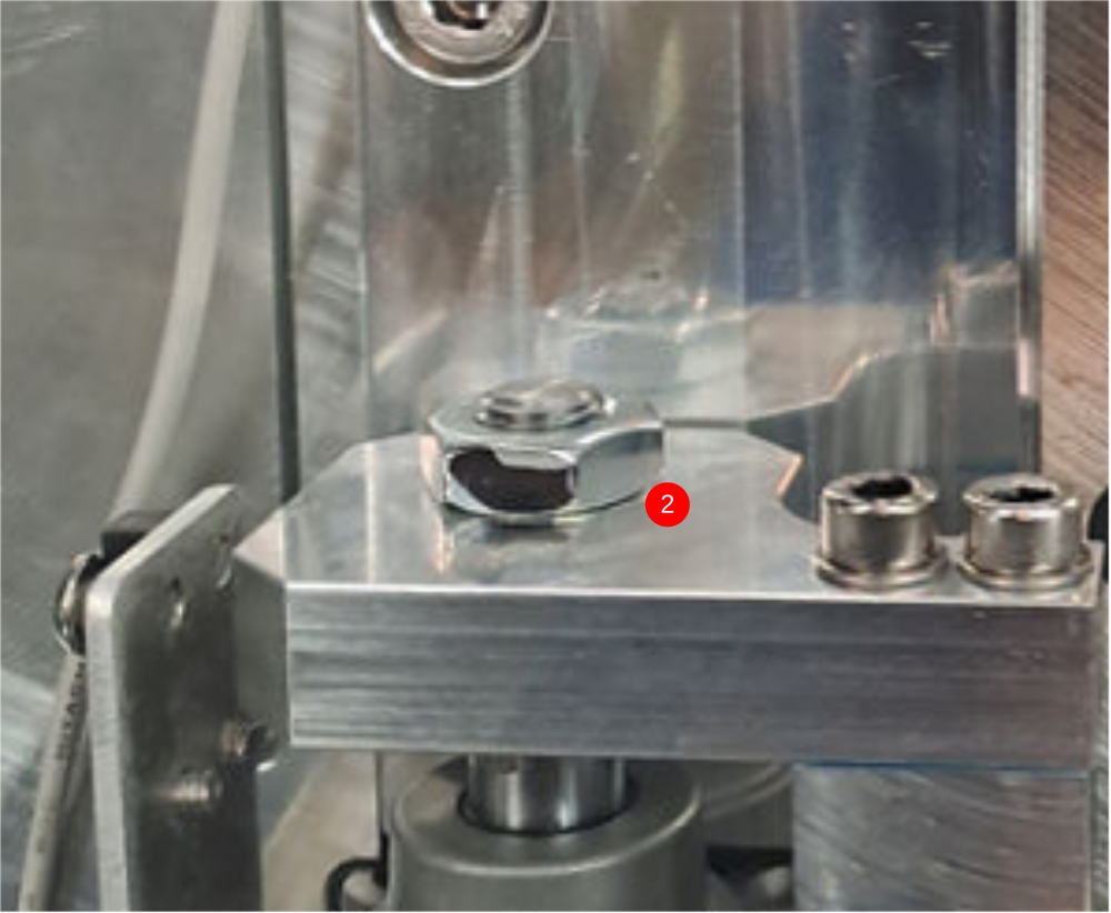
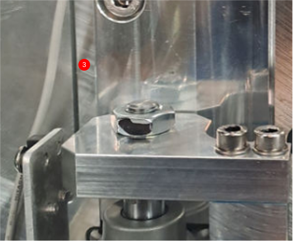
2 Apply Loctite 243 to cylinder nut and tighten
3 Use clearance in holes for mounting at points indicated to achieve cylinder alignment. Cylinder stroke should be even and free along entire stroke
4 Finalise bolts
Repeat on all four single spindles (2,4,6 and 8)
Étape 3 - Mount double plunge spindle cylinder 1,3,5 and 7
Do not add final tension to bolts until alignment has been achieved
1 Attach pre built cylinder anchor to end of cylinder
2 Position pre built cylinder on slide base assembly as shown
3 Use 2 off m5 x 25 socket caps with A form washers to attach to slide base
4 Temporarily mount D0007649 with 1 off m6 x 20 socket cap
5 Attach D0007790 cylinder anchor with 4 off M6 x 20 socket caps
6 Attach Cylinder base to anchor with 4 off M6x 20 socket caps
Étape 4 - Align components and set position
1 Use cylinder stroke adjustment to align these two faces
2 Apply Loctite 243 to cylinder nut and tighten
3 Use clearance in holes for mounting at points indicated to achieve cylinder alignment. Cylinder stroke should be even and free along entire stroke
4 Finalise bolts
Repeat on all four single spindles (1,3,5 and 7))
Étape 5 - Attach single plunge motor plate

Draft
 Français
 English
 Deutsch
 Español
 Italiano
 Português