| [version en cours de rédaction] | [version en cours de rédaction] |
(Page créée avec « {{Tuto Details |Main_Picture=Stage_2_spindle_assembly_Screenshot_47.png |Main_Picture_annotation={"version":"2.4.6","objects":[{"type":"image","version":"2.4.6","originX":... ») |
|||
| Ligne 13 : | Ligne 13 : | ||
{{Materials}} | {{Materials}} | ||
{{EPI}} | {{EPI}} | ||
| + | {{Tuto Step | ||
| + | |Step_Title=<translate>Unless otherwise stated</translate> | ||
| + | |Step_Content=<translate>Use Loctite 243 on all fasteners | ||
| + | |||
| + | Pen mark bolts when finalised</translate> | ||
| + | |Step_Picture_00=R0000712E_Rotary_Trunking_Screenshot_2023-05-31_084239.png | ||
| + | }} | ||
{{Tuto Step | {{Tuto Step | ||
|Step_Title=<translate>Mount single plunge spindle cylinder 2,4,6 and 8</translate> | |Step_Title=<translate>Mount single plunge spindle cylinder 2,4,6 and 8</translate> | ||
| Ligne 103 : | Ligne 110 : | ||
{{Tuto Step | {{Tuto Step | ||
|Step_Title=<translate>Attach single plunge motor plate</translate> | |Step_Title=<translate>Attach single plunge motor plate</translate> | ||
| − | |Step_Content=<translate></translate> | + | |Step_Content=<translate>4 off |
| + | |||
| + | |||
| + | 1 Attach D0007686 motor plate to elte motor using 4 off m6 x 12 socket caps and 2 off 6mmx 20 dowels | ||
| + | |||
| + | |||
| + | 2 Attach to single spindle using 4 off m6 x 20 socket caps | ||
| + | |||
| + | Ensure that motor plate butts up to indicated part and also register is aligned as shown | ||
| + | |||
| + | <br /></translate> | ||
|Step_Picture_00=Stage_2_spindle_assembly_Screenshot_59.png | |Step_Picture_00=Stage_2_spindle_assembly_Screenshot_59.png | ||
| + | |Step_Picture_00_annotation={"version":"2.4.6","objects":[{"type":"image","version":"2.4.6","originX":"left","originY":"top","left":0,"top":0,"width":657,"height":581,"fill":"rgb(0,0,0)","stroke":null,"strokeWidth":0,"strokeDashArray":null,"strokeLineCap":"butt","strokeDashOffset":0,"strokeLineJoin":"miter","strokeMiterLimit":4,"scaleX":0.91,"scaleY":0.91,"angle":0,"flipX":false,"flipY":false,"opacity":1,"shadow":null,"visible":true,"clipTo":null,"backgroundColor":"","fillRule":"nonzero","paintFirst":"fill","globalCompositeOperation":"source-over","transformMatrix":null,"skewX":0,"skewY":0,"crossOrigin":"","cropX":0,"cropY":0,"src":"https://stuga.dokit.app/images/7/79/Stage_2_spindle_assembly_Screenshot_59.png","filters":[]},{"type":"wfnumberedbullet","version":"2.4.6","originX":"left","originY":"top","left":283,"top":89,"width":25,"height":25,"fill":"rgb(0,0,0)","stroke":"#FF0000","strokeWidth":0,"strokeDashArray":null,"strokeLineCap":"butt","strokeDashOffset":0,"strokeLineJoin":"miter","strokeMiterLimit":4,"scaleX":1,"scaleY":1,"angle":0,"flipX":false,"flipY":false,"opacity":1,"shadow":null,"visible":true,"clipTo":null,"backgroundColor":"","fillRule":"nonzero","paintFirst":"fill","globalCompositeOperation":"source-over","transformMatrix":null,"skewX":0,"skewY":0,"objects":[{"type":"circle","version":"2.4.6","originX":"center","originY":"center","left":0,"top":0,"width":24,"height":24,"fill":"#FF0000","stroke":null,"strokeWidth":1,"strokeDashArray":null,"strokeLineCap":"butt","strokeDashOffset":0,"strokeLineJoin":"miter","strokeMiterLimit":4,"scaleX":1,"scaleY":1,"angle":0,"flipX":false,"flipY":false,"opacity":1,"shadow":null,"visible":true,"clipTo":null,"backgroundColor":"","fillRule":"nonzero","paintFirst":"fill","globalCompositeOperation":"source-over","transformMatrix":null,"skewX":0,"skewY":0,"radius":12,"startAngle":0,"endAngle":6.283185307179586},{"type":"text","version":"2.4.6","originX":"center","originY":"center","left":0,"top":0,"width":7.79,"height":15.82,"fill":"rgba(255,255,255,255)","stroke":null,"strokeWidth":1,"strokeDashArray":null,"strokeLineCap":"butt","strokeDashOffset":0,"strokeLineJoin":"miter","strokeMiterLimit":4,"scaleX":1,"scaleY":1,"angle":0,"flipX":false,"flipY":false,"opacity":1,"shadow":null,"visible":true,"clipTo":null,"backgroundColor":"","fillRule":"nonzero","paintFirst":"fill","globalCompositeOperation":"source-over","transformMatrix":null,"skewX":0,"skewY":0,"text":"1","fontSize":14,"fontWeight":"normal","fontFamily":"arial","fontStyle":"normal","lineHeight":1.16,"underline":false,"overline":false,"linethrough":false,"textAlign":"left","textBackgroundColor":"","charSpacing":0,"styles":{} }],"number":1}],"height":531,"width":600} | ||
| + | |Step_Picture_01=Stage_2_spindle_assembly_Screenshot_60.png | ||
| + | |Step_Picture_02=Stage_2_spindle_assembly_Screenshot_61.png | ||
| + | |Step_Picture_03=Stage_2_spindle_assembly_Screenshot_62.png | ||
}} | }} | ||
{{Notes}} | {{Notes}} | ||
{{PageLang | {{PageLang | ||
| + | |Language=en | ||
|SourceLanguage=none | |SourceLanguage=none | ||
|IsTranslation=0 | |IsTranslation=0 | ||
| − | |||
}} | }} | ||
{{Tuto Status | {{Tuto Status | ||
|Complete=Draft | |Complete=Draft | ||
}} | }} | ||
Version du 1 juin 2023 à 14:01
2nd stage of assembly of spindle assemblies


Difficulté
Moyen
Durée
2 heure(s)
Sommaire
- 1 Étape 1 - Unless otherwise stated
- 2 Étape 2 - Mount single plunge spindle cylinder 2,4,6 and 8
- 3 Étape 3 - Align components and set position
- 4 Étape 4 - Mount double plunge spindle cylinder 1,3,5 and 7
- 5 Étape 5 - Align components and set position
- 6 Étape 6 - Attach single plunge motor plate
- 7 Commentaires
Étape 1 - Unless otherwise stated
Use Loctite 243 on all fasteners
Pen mark bolts when finalised

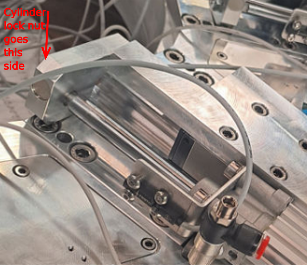
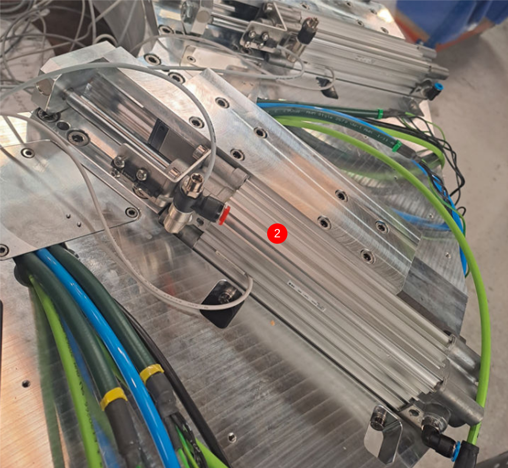
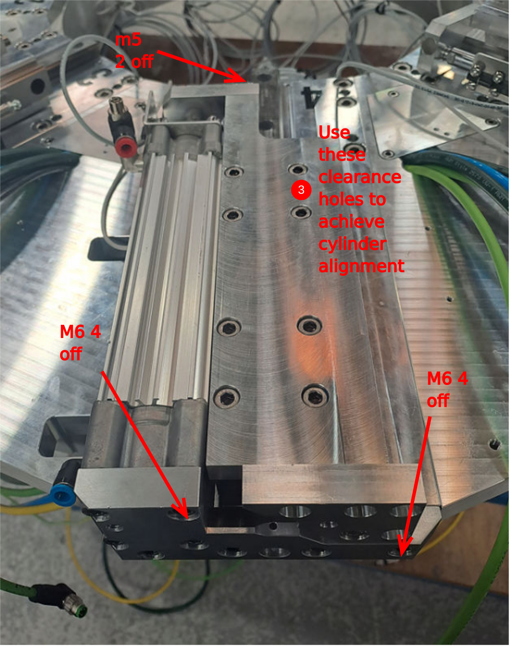
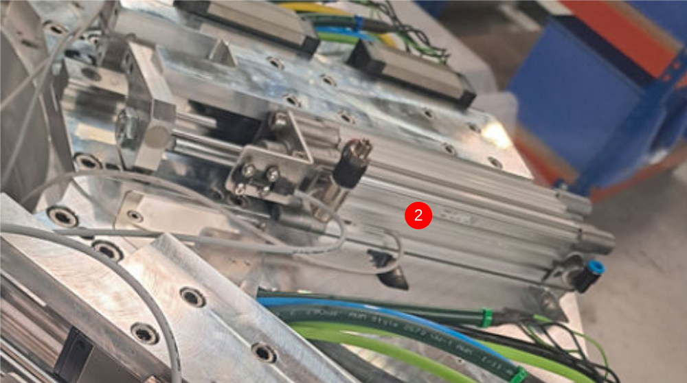
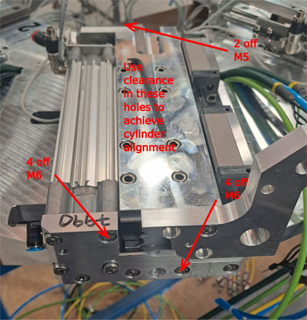
Étape 2 - Mount single plunge spindle cylinder 2,4,6 and 8
Do not add final tension to bolts until alignment has been achieved
1 Attach pre built cylinder anchor to end of cylinder
2 Position pre built cylinder on slide base assembly as shown
3 Use 2 off m5 x 25 socket caps with A form washers to attach to slide base
4 Temporarily mount D0007648 with 1 off m6 x 20 socket cap
5 Attach D0007790 cylinder anchor with 4 off M6 x 20 socket caps
6 Attach Cylinder base to anchor with 4 off M6x 20 socket caps
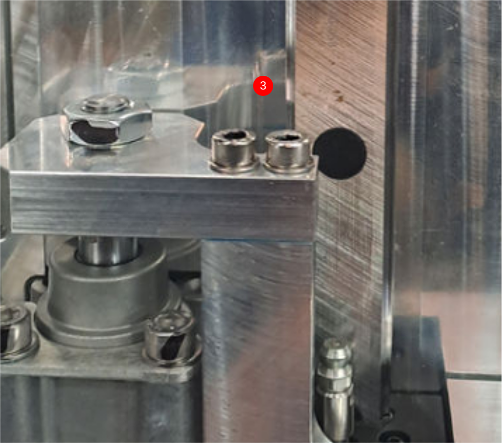
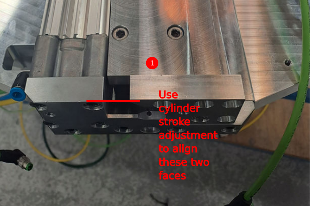
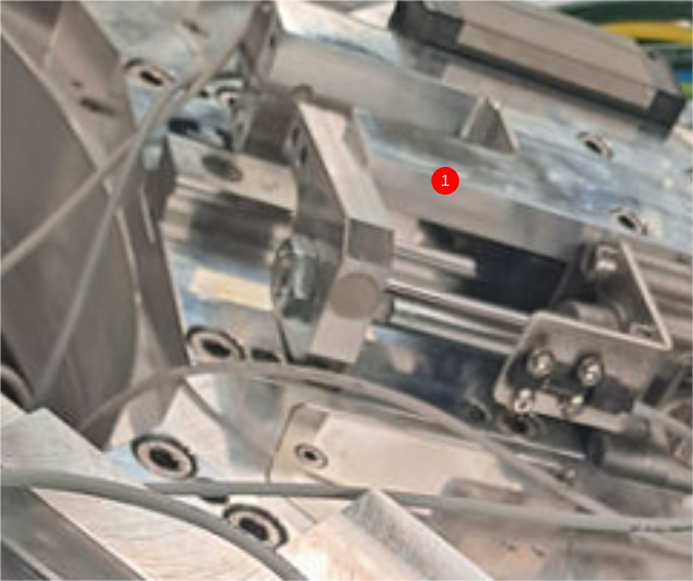
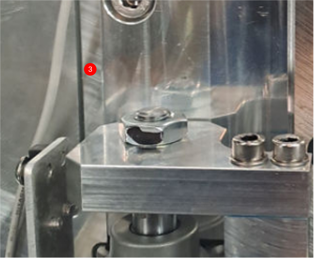
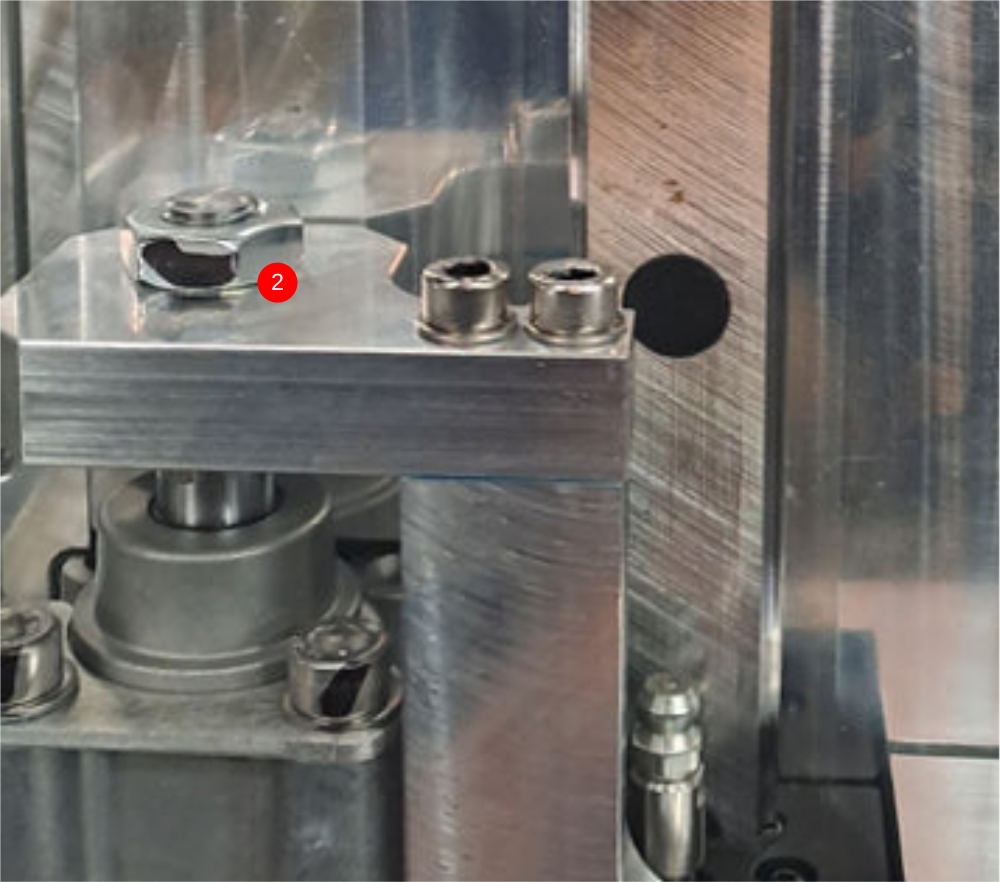
Étape 3 - Align components and set position
1 Use cylinder stroke adjustment to align these two faces
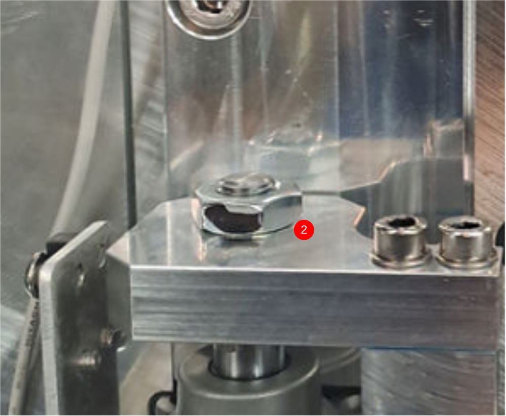
2 Apply Loctite 243 to cylinder nut and tighten
3 Use clearance in holes for mounting at points indicated to achieve cylinder alignment. Cylinder stroke should be even and free along entire stroke
4 Finalise bolts
Repeat on all four single spindles (2,4,6 and 8)
Étape 4 - Mount double plunge spindle cylinder 1,3,5 and 7
Do not add final tension to bolts until alignment has been achieved
1 Attach pre built cylinder anchor to end of cylinder
2 Position pre built cylinder on slide base assembly as shown
3 Use 2 off m5 x 25 socket caps with A form washers to attach to slide base
4 Temporarily mount D0007649 with 1 off m6 x 20 socket cap
5 Attach D0007790 cylinder anchor with 4 off M6 x 20 socket caps
6 Attach Cylinder base to anchor with 4 off M6x 20 socket caps
Étape 5 - Align components and set position
1 Use cylinder stroke adjustment to align these two faces
2 Apply Loctite 243 to cylinder nut and tighten
3 Use clearance in holes for mounting at points indicated to achieve cylinder alignment. Cylinder stroke should be even and free along entire stroke
4 Finalise bolts
Repeat on all four single spindles (1,3,5 and 7))
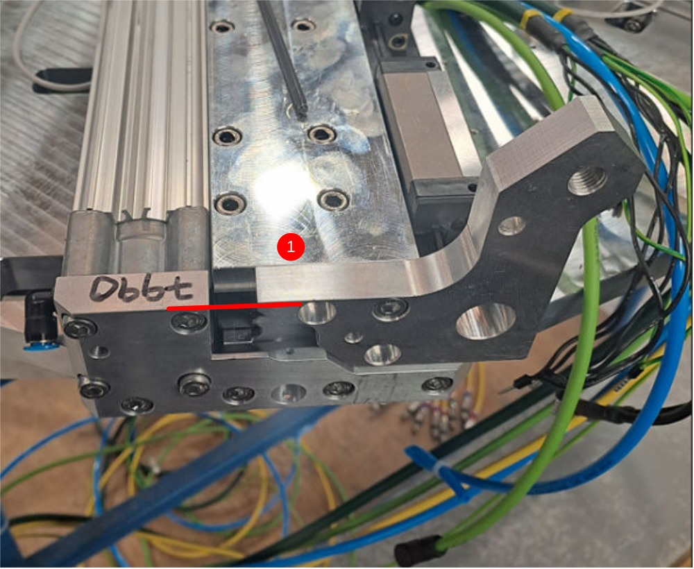
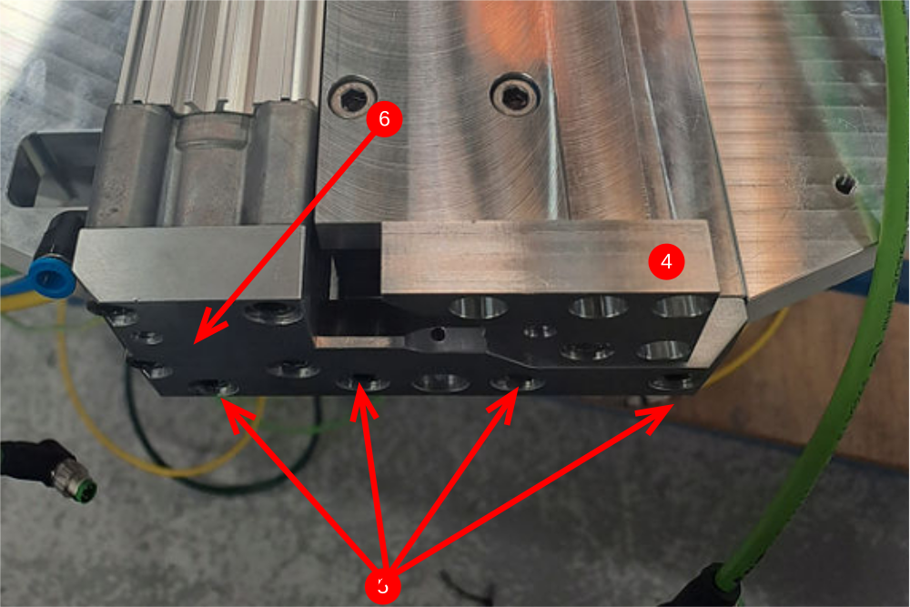
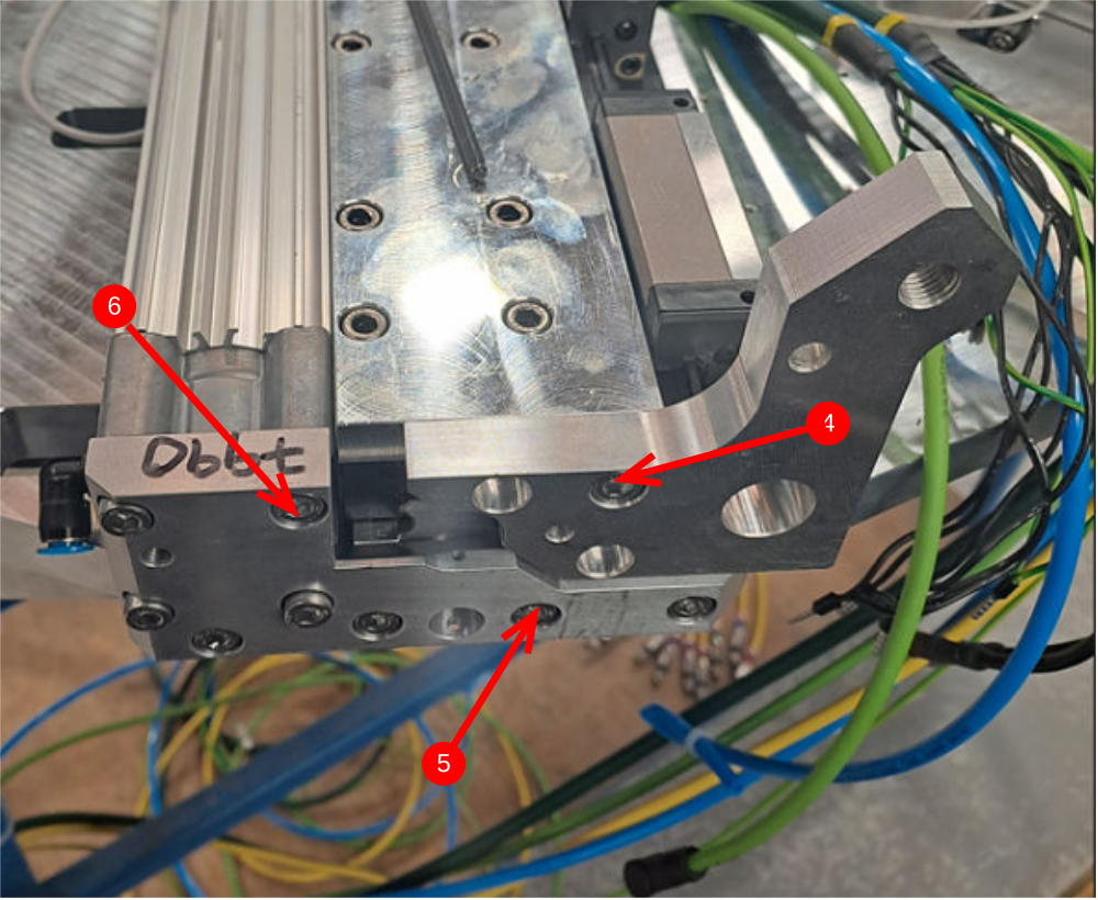
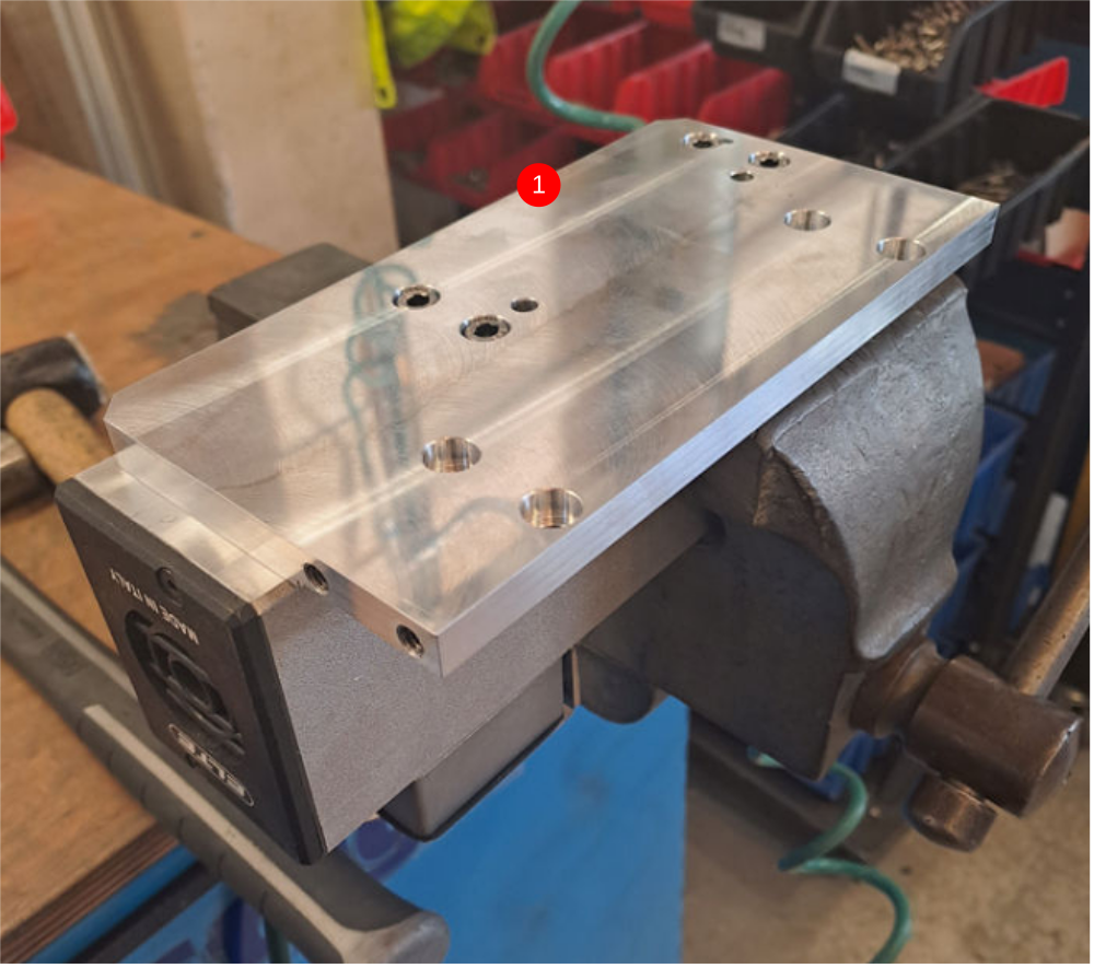
Étape 6 - Attach single plunge motor plate
4 off
1 Attach D0007686 motor plate to elte motor using 4 off m6 x 12 socket caps and 2 off 6mmx 20 dowels
2 Attach to single spindle using 4 off m6 x 20 socket caps
Ensure that motor plate butts up to indicated part and also register is aligned as shown


Draft
 Français
 English
 Deutsch
 Español
 Italiano
 Português