Instructions for correct mounting and set up of width sensor assembly

Difficulté
Moyen
Durée
1 heure(s)
Sommaire
- 1 Introduction
- 2 Étape 1 - Unless otherwise stated
- 3 Étape 2 - Ecr raised for spacer block
- 4 Étape 3 - Fit mounting brackets
- 5 Étape 4 - Fit linear sensor
- 6 Étape 5 - Fit captive magnet ball joint
- 7 Étape 6 - Attach magnet mounting block
- 8 Étape 7 - Set position of magnet ball joint
- 9 Étape 8 - Measure distance
- 10 Étape 9 - Cut M5 studding
- 11 Étape 10 - Connect Magnet block
- 12 Étape 11 - remove magnet mounting block
- 13 Étape 12 - Final fix magnet mounting block
- 14 Étape 13 - Test operation
- 15 Commentaires
Introduction
Tools Required
Standard Hex key set
Standard spanner set
Hack saw
Parts Required
D0000655 Magnet mounting block x 1
E0000461B Analogue linear sensor x 1
E0000463 Captive magnet with ball joint x 1
M5 studding (consumable stock )Étape 1 - Unless otherwise stated
Use locktite 243 on all fasteners
Use loctite 572 on all threaded pneumatic connection
Pen mark all fasteners to show finalised

Étape 2 - Ecr raised for spacer block
Ecr raised 15/08/23 to create new part for additional spacer block required
If not issued, part will require making until new parts are processed
See drawing for details
2 off required

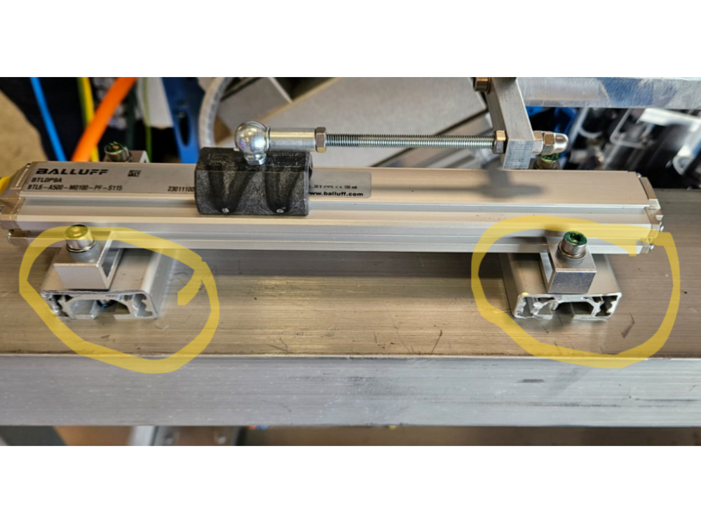
Étape 3 - Fit mounting brackets
Fit mounting brackets and spacers
Ensure to fit supplied top hat bushes
Use longer M5 socket caps to captivate bracket and spacer

Étape 4 - Fit linear sensor
Slide into position linear sensor
Ensure plug connection is facing towards trunking

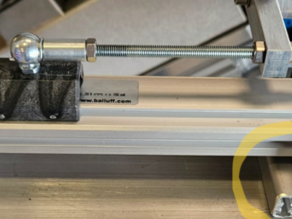
Étape 5 - Fit captive magnet ball joint
Slide on captive magnet ball joint
Ensure correct orientation
Part will indicate which face has to face towards the cable end of the sensor

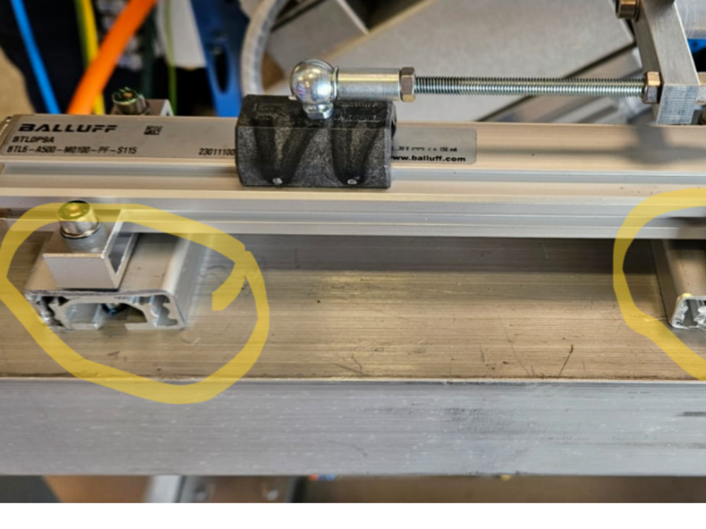
Étape 6 - Attach magnet mounting block
Dry fit magnet mounting block

Étape 7 - Set position of magnet ball joint
Set position of magnet ball joint to align with indicator mark on linear sensor
Ensure side clamp assembly is fully retracted
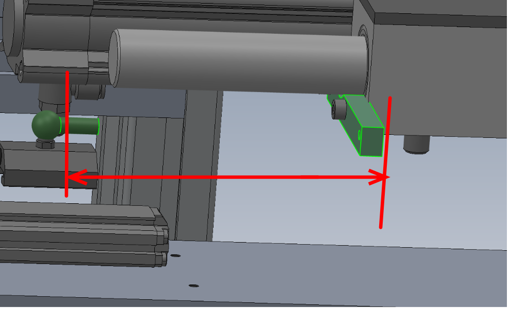
Étape 8 - Measure distance
Please add measurement of studding here to add to dokit please
measure indicated distance to determine M5 studding length required
+10mm to length for additional adjustment
Étape 9 - Cut M5 studding
Cut M5 studding to length calculated

Étape 10 - Connect Magnet block
Attach studding to magnet block, use loctite 243 and M5 nut to lock into position

Étape 11 - remove magnet mounting block
Remove magnet mounting block , add M5 nut to studding and attach magnet block to opposite end of studding
Adjust length to ensure magnet block is aligned with datum mark on linear sensor
Étape 12 - Final fix magnet mounting block
Final fit magnet mounting block to clamp assembly
Finalise locking nut on studding
Étape 13 - Test operation
Ensure side clamp movement is not hindered by attached width sensor assembly
Check when clamp is retracted magnet block aligns perfectly onto indicator mark on linear sensor
Check magnet block is orientated correctly ( cable indicator is facing cable )

Draft
 Français
 English
 Deutsch
 Español
 Italiano
 Português