Fitting the crank upgrade to Z065, Z066, Z067

Difficulté
Difficile
Durée
2 jour(s)
Sommaire
- 1 Introduction
- 2 Étape 1 - Program Eaton Drives before they leave
- 3 Étape 2 - Remove Link arm connecting to rack and pinion
- 4 Étape 3 - Remove pivot shaft and arm
- 5 Étape 4 - Undo clutch and remove Cam
- 6 Étape 5 - Add sprocket to clutch
- 7 Étape 6 - Fix idler plate to upright
- 8 Étape 7 - Fix split sprocket onto drive shaft
- 9 Étape 8 - Drill and pin split sprocket to shaft
- 10 Étape 9 - Add chain minimum length sprocket to sprocket
- 11 Étape 10 - Fit Module C Crank Home sensor plate to Arm 5
- 12 Étape 11 - Fit Module C Crank Out sensor plate to Arm 5
- 13 Étape 12 - Fit Module D Crank Home sensor plate to Arm 5
- 14 Étape 13 - Fit Module D Crank Out sensor plate to Arm 5
- 15 Étape 14 - Fit Module E Crank Out sensor plate to Arm 5
- 16 Étape 15 - Fit Module E Crank Home sensor plate to Arm 5
- 17 Étape 16 - Remove 2 off breaker and contactor Module C
- 18 Étape 17 - Add 2 off single pole breaker Module C
- 19 Étape 18 - Add 2 off Eaton Drive to Module C
- 20 Étape 19 - Add single pole breaker Module E
- 21 Étape 20 - Remove breaker and contactor Module E
- 22 Étape 21 - Add 1 Off Eaton drive to Module E
- 23 Étape 22 - For each Eaton Drive
- 24 Étape 23 - Wire Sensor Cables to EtherCAT boxes
- 25 Étape 24 - Latest software installed
- 26 Étape 25 - Map new Links
- 27 Étape 26 - Test
- 28 Commentaires
Introduction
This upgrade replaces the crank arm assemblies on Z065, Z066 and Z067 with a direct drive system to improve reliability
Étape 1 - Program Eaton Drives before they leave
Running frequency
Control mode
Accel time
Decel time
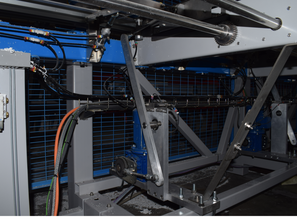
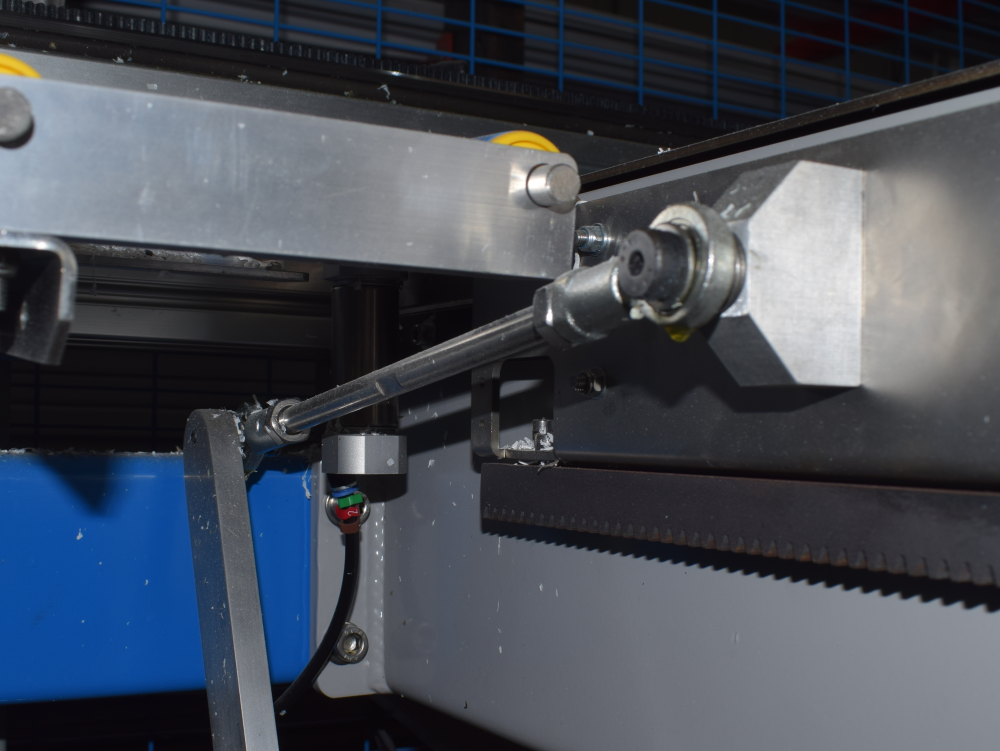
Étape 2 - Remove Link arm connecting to rack and pinion
Étape 3 - Remove pivot shaft and arm


Étape 4 - Undo clutch and remove Cam


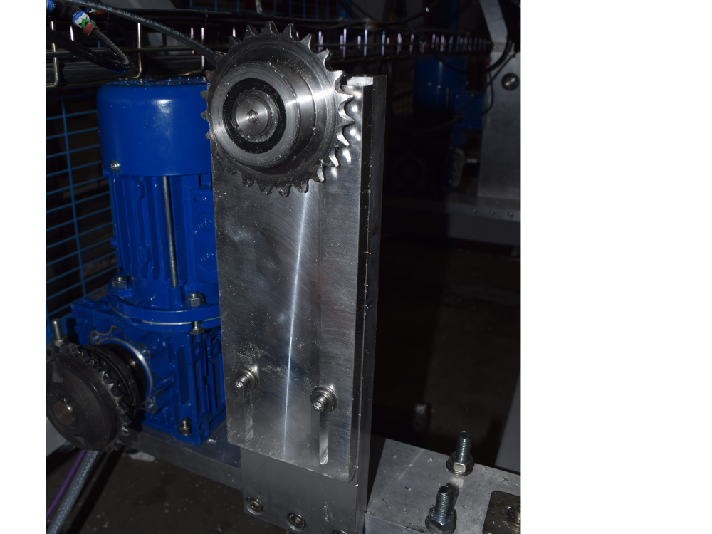
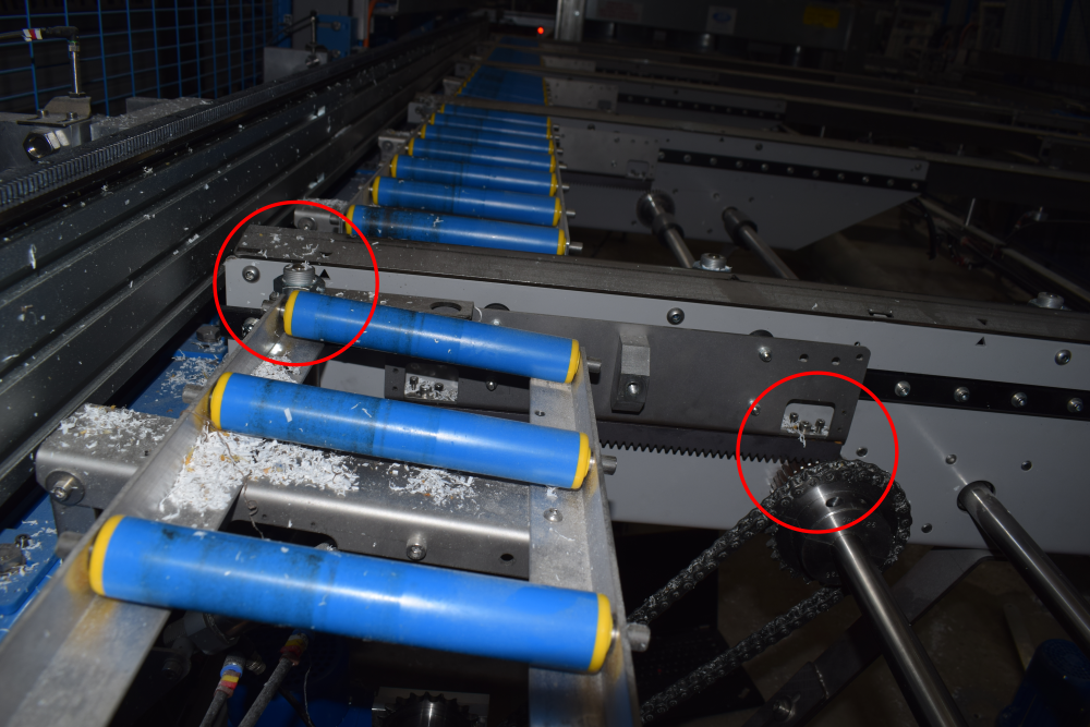
Étape 5 - Add sprocket to clutch
B0001166


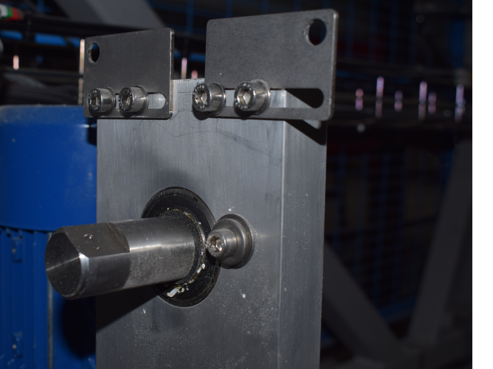
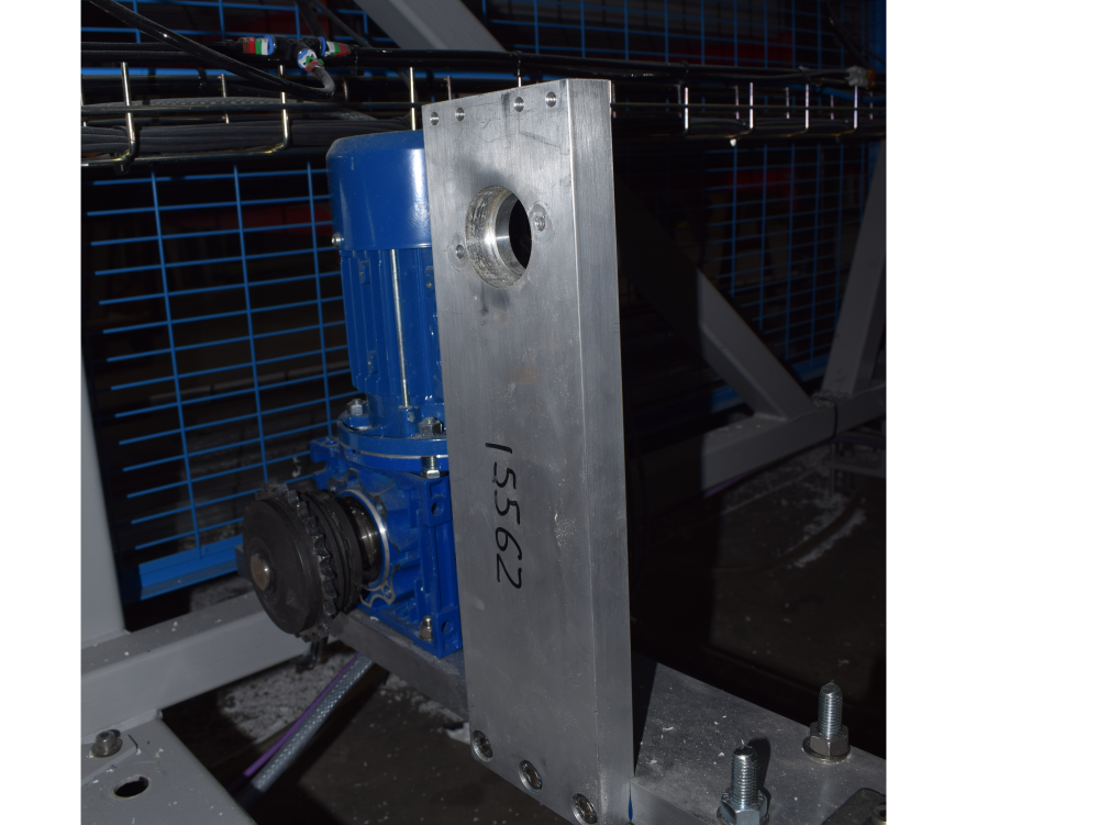
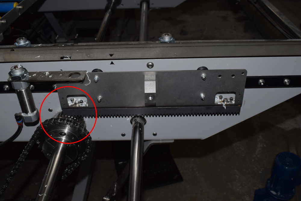
Étape 6 - Fix idler plate to upright
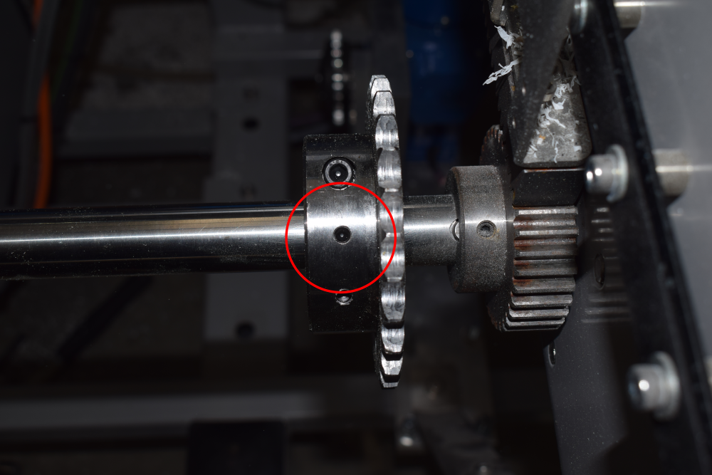
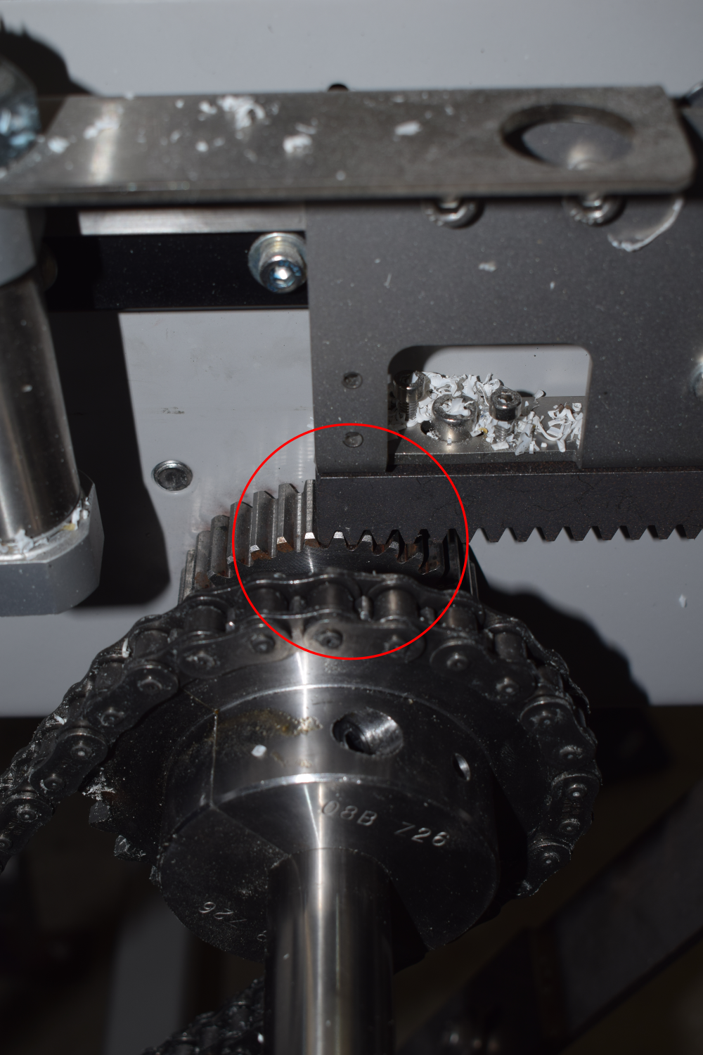
Étape 7 - Fix split sprocket onto drive shaft


Étape 8 - Drill and pin split sprocket to shaft
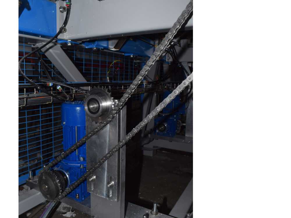
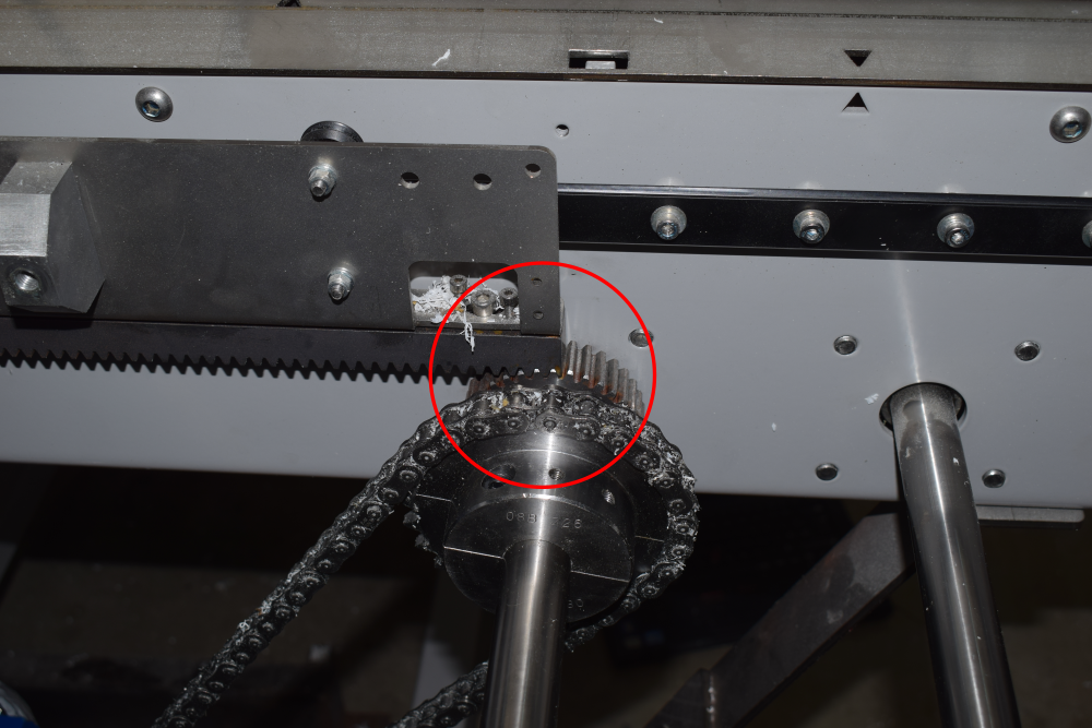
Étape 9 - Add chain minimum length sprocket to sprocket
Use idler to create tension
Étape 10 - Fit Module C Crank Home sensor plate to Arm 5
Sensor cables run to rear Module C cabinet - EtherCAT fieldbus boxes

Étape 11 - Fit Module C Crank Out sensor plate to Arm 5
This one has an extension that may or not be required. See Module D Crank Out Sensor for more info.
Sensor cables run to rear Module C cabinet - EtherCAT fieldbus boxes

Étape 12 - Fit Module D Crank Home sensor plate to Arm 5
Sensor cables run to rear Module C cabinet - EtherCAT fieldbus boxes

Étape 13 - Fit Module D Crank Out sensor plate to Arm 5
This one has an extension
Sensor cables run to rear Module C cabinet - EtherCAT fieldbus boxes


Étape 14 - Fit Module E Crank Out sensor plate to Arm 5
Sensor cables run to rear Module E cabinet - EtherCAT fieldbus boxes


Étape 15 - Fit Module E Crank Home sensor plate to Arm 5
This one has an extension
Sensor cables run to rear Module E cabinet - EtherCAT fieldbus boxes


Étape 16 - Remove 2 off breaker and contactor Module C


Étape 17 - Add 2 off single pole breaker Module C
Tidy wires away for the spare 2 phases
Étape 18 - Add 2 off Eaton Drive to Module C
May need to move trunking or mount directly to side of enclosure.
Étape 19 - Add single pole breaker Module E
Étape 20 - Remove breaker and contactor Module E
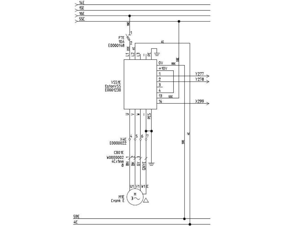
Étape 21 - Add 1 Off Eaton drive to Module E
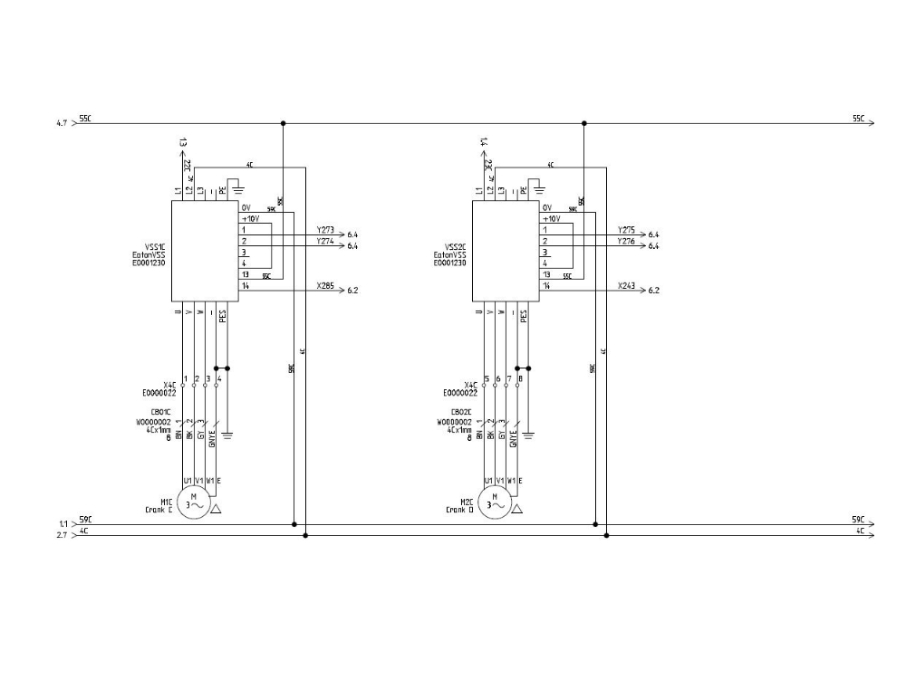
Étape 22 - For each Eaton Drive
- 1 phase
- Neutral
- Earth
- Fwd and Reverse signals
- Wire motor cables directly to bottom of drives
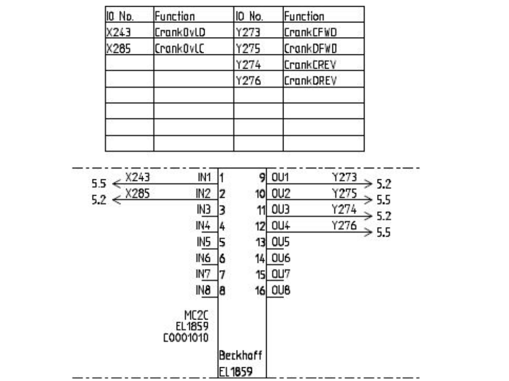
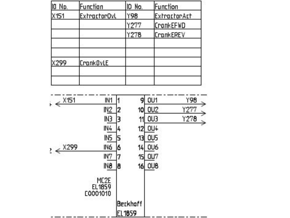
Étape 23 - Wire Sensor Cables to EtherCAT boxes
Module C and D cranks to back of Module C cabinet
Module E crank to back of Module E cabinet


Étape 24 - Latest software installed
Étape 25 - Map new Links
Étape 26 - Test
Draft
 Français
 English
 Deutsch
 Español
 Italiano
 Português