How to fit a Yaskawa Inverter as a replacement in the field

Sommaire
- 1 What is the Yaskawa inverter?
- 2 Mechanical Fitting Notes
- 3 Wiring the Yaskawa Inverter
- 4 Software Upgrades
- 5 Machine Applications
- 5.1 Autoflow TwinCAT 2 Notes
- 6 Checklist
- 7 Testing
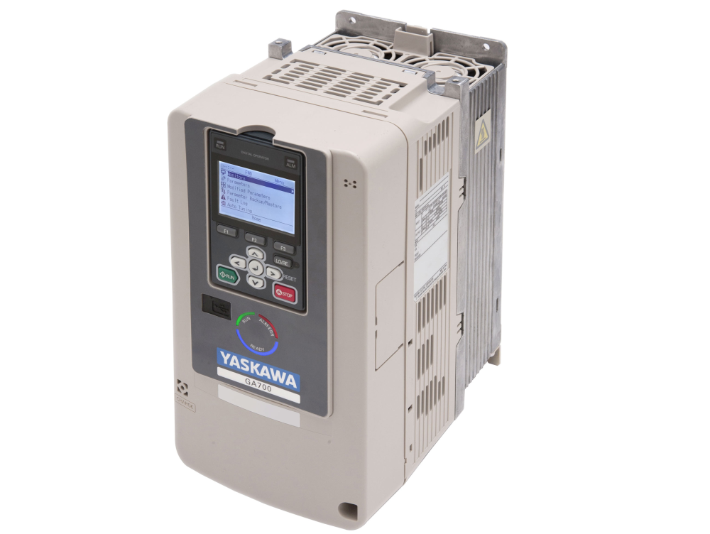
What is the Yaskawa inverter?
- Like the Delta inverter, it has an internal PLC. We have worked alongside Goodwin Electronics to write a PLC program specifically for the Stuga machines.
- Unlike the Delta inverters, when we receive an inverter from Goodwin Electronics, it will already be pre-programmed and ready to run on any machine.
- This inverter can replace the Jaguar and the Delta inverters. It has STO functionality which will be used on new builds and an also be retrospectively wired into machines in the field if needed.
- This inverter has shown to provide more protection in fault scenarios than the Delta inverter. One of the worries of the Delta was how it handled issues on the incoming supply. The Yaskawa inverter has shown resilience to shorts, missing phases, phases to earth and other issues on both incoming and outgoing supplies.
- The Yaskawa inverter adds extra functionality as well. We can now monitor the zero speed of the spindles. This means we can more accurately time when we switch spindle relays on and off. This will hopefully cause less arcing in spindle boxes and premature failure of spindle cards/relays.
Mechanical Fitting Notes
Fitting the Yaskawa inverter in place of a Delta inverter
The Yaskawa has a very similar outer body size to the Delta inverter. This means that it will fit into the same space that the Delta did. However, the hole centres are different. New holes will need to be drilled when first fitting a Yaskawa.
Fitting the Yaskawa inverter in place of a Jaguar inverter
The Yaskawa is much taller than the Jaguar inverter. This may mean that the Yaskawa will not fit in the same space that the Jaguar did. We had the same problem when replacing Jaguar with Delta. There has been occasions in some of the older style ZX cabinets where the plastic trunking had to be re-routed to allow the room for the new inverter to fit.
Wiring the Yaskawa Inverter
This is a general diagram for cabling into the different machine types - more details for each machine will follow

When the inverter is fitted, the screen needs to be removed via the clip on the top. If you do not do this, the connector that is behind the screen can be bent out of place and the screen will not reconnect. The main cover that is at the front of the inverter needs to be removed with the screw at the bottom right. You then have to pinch either side of the inverter and lift the cover up.
You can then start wiring in cables from the original inverter setup as per table in the electrical drawing.
There will be some wiring that needs to be added. The table show all extra wiring that is needed for the inverter. The extra wiring will need to splice off existing cables in the electrical cabinet. The Yaskawa inverter needs more IO than the Jaguar. If there is a Delta fitted, you will find that most of the IO will already be in.
Software Upgrades
Extra Functionality
The Yaskawa inverter has also been programmed to monitor the temperature of the dump resistor. If the machine has a dump resistor with a thermal overload on it, this needs to be wired into the inverter. The alarm for this input is only in fault state when the input is high. This means if you do not have a thermal overload, leave the input terminal empty.
The Yaskawa inverter also has an output to say the spindle is at zero speed. This will need to be wired back into the main machine PLC or IO slices. This will then need a software update from Stuga.
TwinCAT3 Notes
· Timing issues on switching the double plunge configuration means that another IO channel is needed – OuB_InvDP (Y271). This output used to directly control the inverter, not the Y376, Y377, Y58, Y62
· Version 6.2514 or later needed
· Mapping required for Y271
| Control System | Front End Version | Back End Version |
|---|---|---|
| Nextmove Mint | 5.4.4.0 (29/06/16) | 3.9997 (Feb 17) |
| TwinCAT2 | 5.4.4.0 (29/06/16) | See GG |
| TwinCAT3 | Any | 6.2514 (24/10/18) |
Machine Applications
Autoflow TwinCAT 2 Notes
Inverter
· Increase C1-01 accel time on 50Hz to 0.3
· Increase C1-05 accel time on 300Hz to 0.3
· Wire S1 to Module B Output Slice channel 1 (Y63)
· Wire S2 to Module B Output Slice channel 2 (Y63)
· Wire S3 and S4 to Module B Output Slice Channel 3 and 4 (Y376)
· 59a to 0v
· 24v link across 3 other inputs
· Inverter fault direct output (bypass the useless link through the overload relay)
· Inverter reset wire to output slice
· Inverter at zero wire to input slice channel 7 (X308)
· Resistor fault not working correctly, leave disconnected STO??! Inverter powers off on estop, works ok, leave links in HC, H1,H2
Back end
· Double link the double plunge outputs (Y271) 0> Channel 3 and 4
· Link inverter reset (X308) -> Channel 7
· Link inverter zero
· Latest software version
Front end
· Ensure inverter alarm is correct sense
· Parameter Invert300hz=1
· Check inverter display changes to 300hz / 50 HS when spindles are selected
Flowline Mk3 Refurb TwinCAT3
· The phase monitoring device is not needed any more, but it is inactive, so can be left in place.
· Remove the cable 127 connecting SIG to the Delta inverter
· 3 new wires required, Y63 (Inv_300), Y271(Inv_Dp) and X308 (Inv_Zero)
· Y63, Y271 and X308 will need mapping in TwinCAT3 and adding to IO Ref
· Parameter Invert300Hz needs to be true
· Latest Software needs to be added to sort timings and use of Y63, Y271 and X308
| Function | Wire Number / Colour | Yaskawa Terminal |
| Mains In L1, L2, L3 | 26, 27,28 | L1, L2, L3 |
| Motor Out U, V, W | 126, 127, 128 | T1, T2, T3 |
| Input: Select 50Hz #1 | Y63
Wire to MC4 Ou7 |
S1 |
| Input: Select 50Hz #2 | Link to S1 | S2 |
| Input: Double Plunge #1 | Y271
Wire To MC4 Ou8 |
S3 |
| Input: Double Plunge #2 | Link to S3 | S4 |
| Input: Motor Run | Y358 | S5 |
| Input: Inverter Reset | Y374 | S6 |
| Input: Resistor Thermal Ovl | n/c | S7 |
| Input: Motor 2 Safety | Link to M4 | S8 |
| Inverter OK 24v | 24v (Yellow) | MC |
| Inverter OK Output | X342 | MB |
| Output 24v Supply | 24v (Yellow) | M1, M3 |
| Output: Spindle At Zero | New Wire X308
To io slice MC5 Input channel 8 |
M2 |
| Output: Motor 2 Safety | Link to S8 | M4 |
| STO Override | Link | H1, H2, HC |
| External 0v | 0v (White) | SC |
| Braking Resistor | 1,2 | B1, B2 |
IODef.mul additions
Inv_Zero,308,1,0,0,0,0,1,12,0
Inv_DP  ,271,2,0,0,0,0,1,10,0
Inv_300 ,63,2,0,0,0,0,1,11,0
ZX4 Mk5/6 (Beckhoff) Retrofitting in place of Delta
Electrical Highlights:
· Ensure 24v connected to M1 and M3
· Y271(OuB_InvDp) uses the existing cabling in S4, currently labelled Y377
o A link will need to be added up to S3, where there currently is a cable labelled Y376
· Using Y376 cable, remove the labelling and label as X308 (InA_InvZero)
o The other end of this currently goes to the beckhoff slice MC3B pin 15 (OU1). This now needs to be moved to pin 4 (IN4), and relabelled.
· A link wire between M4 and S8 needs to be added
· Remove Wire 60B (From Aux contact on F5 to RC1 on Delta Inverter). Not needed because Inverter OK signal does not need to be in series with F5 overload
· Remove wire 61B from Phase monitor to Delta MI6. Not needed because Yaskawa does phase monitoring internally
· 2 additional 24v control relays needed for interfacing TwinSafe to the STO inputs as per diagram

| Function | Wire Number / Colour | Yaskawa Terminal |
| Mains In L1, L2, L3 | 21B, 22B, 23B | L1, L2, L3 |
| Motor Out U, V, W | 70B, 71B, 72B | T1, T2, T3 |
| Input: Select 50Hz #1 | n/c | S1 |
| Input: Select 50Hz #2 | n/c | S2 |
| Input: Double Plunge #1 | Y271 -Wire To MC4 Ou8 | S3 |
| Input: Double Plunge #2 | Link to S3 | S4 |
| Input: Motor Run | Y358 | S5 |
| Input: Inverter Reset | Y374 | S6 |
| Input: Resistor Thermal Ovl | n/c | S7 |
| Input: Motor 2 Safety | Link to M4 | S8 |
| Inverter OK 24v | 24v (Yellow) | MC |
| Inverter OK Output | X342 | MB |
| Output 24v Supply | 24v (Yellow) | M1, M3 |
| Output: Spindle At Zero | New Wire X308 -To io slice MC3B IN4 | M2 |
| Output: Motor 2 Safety | Link to S8 | M4 |
| STO Override | Add 2 relays as per diagram.
Relay control via Beckhoff safety slices |
H1, H2, HC |
| External 0v | 0v (White) | SC |
| Braking Resistor | 1,2 | B1, B2 |
IODef.mul additions
Inv_Zero,308,1,0,0,0,0,19,5,0
Inv_DP  ,271,2,0,0,0,0,19,6,0
ZX5 Retrofitting in place of Delta
Electrical Highlights:
- Ensure 24v connected to M1 and M3
- Y271(OuB_InvDp) uses the existing cabling in S4, currently labelled Y377
- A link will need to be added up to S3, where there currently is a cable labelled Y376
- Using Y376 cable, remove the labelling and label as X308 (InA_InvZero)
- The other end of this currently goes to the beckhoff slice MC2B pin 15 (OU7). This now needs to be moved to pin 4 (IN4), and relabelled.
- A link wire between M4 and S8 needs to be added
- 2 additional 24v control relays needed for interfacing TwinSafe to the STO inputs as per diagram
| Function | Wire Number / Colour | Yaskawa Terminal |
| Mains In L1, L2, L3 | 21B, 22B, 23B | L1, L2, L3 |
| Motor Out U, V, W | 70B, 71B, 72B | T1, T2, T3 |
| Input: Select 50Hz #1 | n/c | S1 |
| Input: Select 50Hz #2 | n/c | S2 |
| Input: Double Plunge #1 | Y271 -Wire To MC2B Ou8 | S3 |
| Input: Double Plunge #2 | Link to S3 | S4 |
| Input: Motor Run | Y358 | S5 |
| Input: Inverter Reset | Y374 | S6 |
| Input: Resistor Thermal Ovl | n/c | S7 |
| Input: Motor 2 Safety | Link to M4 | S8 |
| Inverter OK 24v | 24v (Yellow) | MC |
| Inverter OK Output | X342 | MB |
| Output 24v Supply | 24v (Yellow) | M1, M3 |
| Output: Spindle At Zero | New Wire X308 -To io slice MC2B IN4 | M2 |
| Output: Motor 2 Safety | Link to S8 | M4 |
| STO Override | Add 2 relays as per diagram.
Relay control via Beckhoff safety slices |
H1, H2, HC |
| External 0v | 0v (White) | SC |
| Braking Resistor | 1,2 | B1, B2 |
IODef.mul additions
Inv_Zero,308,1,0,0,0,0,19,3,0
Inv_DP  ,271,2,0,0,0,0,19,4,0
Flowline Mk3 Refurb Notes (Nextmove E100)
Electrical Highlights:
- To create space for the new inverter, remove the contactor and timer for delaying the drive switching (If they exist) – these are normally located under the old inverter. This switching was only necessary when a DOS PC was used, the contactor can be bypassed.
- The supply to the new inverter needs to be wired directly rather than via the estop contactor. The new drive has “STO” (Safe Torque Off) inputs that are wired through two 24v dc relays (supplied). This means when ESTOP is pressed, the drive does not power off, it goes into safe torque off mode. This is a much more reliable system than “crash” shutting off the inverter on estop.
- The phase monitoring device (if fitted) is not needed any more, but it is inactive, so can be left in place.
- The 50Hz relays for RY1 and RY4 should be removed and the wires RY1, RY4 wired directly to the inverter inputs S1 and S2. This removes the relays as a potential point of failure.
- Ensure 24v connected to MC, M1 and M3
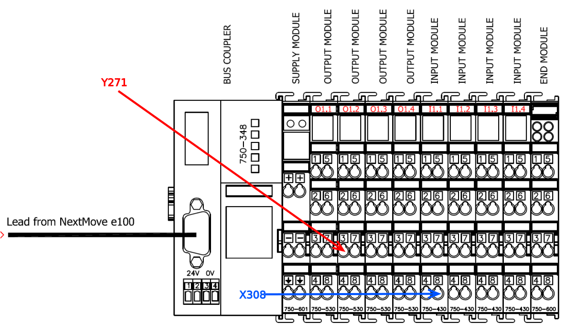
- New cable for Y271(OuB_InvDp) from S3 and S4 (link), connect to Output channel 8 on 1st IO slice. Note: the SPDP wire (Y99) may be numbered Y58 and in the output channel 8. For consistency, make:
- Ou7 - SPDP – Y99
- Ou8 – Inv_DP – Y271
- New Cable X308 (InA_InvZero) from M2, connect to Input channel 7 on 4th IO slice.
- A link wire between M4 and S8 needs to be added
- 2 additional 24v control relays needed for interfacing Estop to the STO inputs as per diagram
- The Inverter OK signal (X27) should be wired directly from the inverter to the input slice – it is probably wired via the inverter overload relay auxiliary contact – this is now redundant and will cause confusion
- Remove the link SP to SC. This is for grounding an internal PSU that is not used
- Remove X99 wire, this was a feedback check to ensure the 50Hz relays had switched, no not required
| Function | Wire Number / Colour | Yaskawa Terminal |
| Mains In L1, L2, L3 | 26, 27, 28 | L1, L2, L3 |
| Motor Out U, V, W | 26B, 27B, 28B | T1, T2, T3 |
| Input: Select 50Hz #1 | RY1 | S1 |
| Input: Select 50Hz #2 | RY4 | S2 |
| Input: Double Plunge #1 | Y271 -Wire To Output channel 8 on 1st IO slice | S3 |
| Input: Double Plunge #2 | Link to S3 | S4 |
| Input: Motor Run | Y9 | S5 |
| Input: Inverter Reset | Y6 | S6 |
| Input: Resistor Thermal Ovl | n/c | S7 |
| Input: Motor 2 Safety | Link to M4 | S8 |
| Inverter OK 24v | 24v (Yellow) | MC |
| Inverter OK Output | X27 | MB |
| Output 24v Supply | 24v (Yellow) | M1, M3 |
| Output: Spindle At Zero | New Wire X308 - connect to Input channel 7 on 4th IO slice. | M2 |
| Output: Motor 2 Safety | Link to S8 | M4 |
| STO Override | Add 2 relays as per diagram. | H1, H2, HC |
| External 0v | 0v (White) | SC |
| Braking Resistor | 1,2 | B1, B2 |
IODef.mul additions
INVDP   ,616,2,8,7,0,0,1,7,1
InZRO   ,608,1,8,14,0,0,2,11,1

Ensure SPDP is:
SPDP   ,569,2,8,6,0,0,1,6,V

Delete any reference to IS300 input
Alarms.mul
Ensure the alarms are set for each individual spindle:
41,MOVL,False,SPIN1,True,0,4,Spindle 1 Alarm,True,False
42,MOVL,False,SPIN2,True,0,4,Spindle 2 Alarm,True,False
43,MOVL,False,SPIN3,True,0,4,Spindle 3 Alarm,True,False
44,MOVL,False,SPIN4,True,0,4,Spindle 4 Alarm,True,False
45,MOVL,False,SPIN5,True,0,4,Spindle 5 Alarm,True,False
46,MOVL,False,SPIN6,True,0,4,Spindle 6 Alarm,True,False
The MOVL should be High when the inverter is OK.
Remove any alarms relating to IS300 input
Front end
- Ensure inverter alarm is correct sense
- Parameter Invert300hz=1
- Parameter InverterOKHigh=1
- Parameter psInvDecel300Hz=400
- Check inverter display changes to 300hz / 50 HS when spindles are selected
Other software
Download and install Yaskawa DriveWizard
Ensure the Yaskawa USB is connected to the PC
Find the COM port it is connected to (use Device Manager Ports) – this is usually COM3. If there are other connections on the same COM port, right click and uninstall them (EDG). This will need a reboot after uninstalling
Using DriveWizard, or via the physical keypad on the device, change the following parameters
| No | Description | New Value |
| C1-01 | 50Hz Accel Time | 0.5 |
| C1-02 | 50Hz Decel Time | 0.5 |
| C1-05 | 300Hz Accel Time | 0.4 |
| C1-06 | 300Hz Decel Time | 0.4 |
ZX3/Microline Replace VXR Notes (Nextmove E100)

Electrical Highlights:
- The inverter will need to be located on the side of the cabinet, as the Yaskawa is taller than the VXR
- The supply to the new inverter needs to be wired directly rather than via the estop contactor. The new drive has “STO” (Safe Torque Off) inputs that are wired through two 24v dc relays (supplied). This means when ESTOP is pressed, the drive does not power off, it goes into safe torque off mode. This is a much more reliable system than “crash” shutting off the inverter on estop.
- The phase monitoring device (if fitted) is not needed any more, but it is inactive, so can be left in place.
- Ensure 24v connected to MC, M1 and M3
- The Zx3 and Microline have a set of switchover contactors to select 50Hz (Mains) or 300Hz (Inverter). Therefore, the inverter does not need to do the 50 / 300Hz switching as on later machine models.
- New cable for Y271 (InvDp) from S3 and S4 (link), connect Output channel 5 on 2nd Output slice (labelled 5)
- New Cable X308 (InA_InvZero) from M2, connect to input channel 8 on 1st IO slice (labelled 8)..
- A link wire between M4 and S8 needs to be added
- 2 additional 24v control relays needed for interfacing Estop to the STO inputs as per diagram

- The Inverter OK signal (X48) should be wired directly from the inverter to the input slice – it is probably wired via the inverter overload relay auxiliary contact – this is now redundant and will cause confusion
- Remove the link SP to SC. This is for grounding an internal PSU that is not used
- Inverter Reset function is done with Y34 SRST. The VXR inverter was powered off on estop, so did not need a reset function. Tag in to a Y34 cable on any servo drive (PL4 pin 2)
| Function | Wire Number / Colour | Yaskawa Terminal |
| Mains In L1, L2, L3 | 60, 61, 62 | L1, L2, L3 |
| Motor Out U, V, W | 53, 54, 55 | T1, T2, T3 |
| Input: Select 50Hz #1 | Not connected (constant 300Hz) | S1 |
| Input: Select 50Hz #2 | Not connected (constant 300Hz) | S2 |
| Input: Double Plunge #1 | Y271 -Wire To Output channel 5 on 2nd Output slice (labelled 3) | S3 |
| Input: Double Plunge #2 | Link to S3 | S4 |
| Input: Motor Run | Y31 – extend to run directly
Remove the relay R58 and wires 51, 52 |
S5 |
| Input: Inverter Reset | Y34 – Splice into servo reset – loops across each of the servo drives | S6 |
| Input: Resistor Thermal Ovl | n/c | S7 |
| Input: Motor 2 Safety | Link to M4 | S8 |
| Inverter OK 24v | 24v (Yellow) | MC |
| Inverter OK Output | X48
Remove wire 30A |
MB |
| Output 24v Supply | 24v (Yellow) | M1, M3 |
| Output: Spindle At Zero | New Wire X308 - connect to Input channel 8 on 1st IO slice (labelled 8). | M2 |
| Output: Motor 2 Safety | Link to S8 | M4 |
| STO Override | Add 2 relays as per diagram. | H1, H2, HC |
| External 0v | 0v (White) | SC |
| Braking Resistor | Br+, Br- | B1, B2 |


IODef.mul additions
INVDP,616,2,8,12,0,0,18,1,1
InZRO,608,1,8,7,0,0,18,2,1

Edit the following iodefs to put the all the spindle control on the spindle IO screen – makes testing much easier

INVOK,542,1,8,23,0,0,18,6,0
HZ50,578,2,0,4,0,0,18,7,D
HZ300,579,2,0,5,0,0,18,8,E
SMOT,558,2,8,15,0,1,18,3,Z
RST,574,2,8,18,0,0,18,4,F
Alarms.mul
Ensure the alarms are set for each individual spindle:
41,INVOK,False,SPIN1,True,0,4,Spindle 1 Alarm,True,False
42,INVOK,False,SPIN2,True,0,4,Spindle 2 Alarm,True,False
43,INVOK,False,SPIN3,True,0,4,Spindle 3 Alarm,True,False
44,INVOK,False,SPIN4,True,0,4,Spindle 4 Alarm,True,False
45,INVOK,False,SPIN5,True,0,4,Spindle 5 Alarm,True,False
46,INVOK,False,SPIN6,True,0,4,Spindle 6 Alarm,True,False
47,INVOK,False,SPIN7,True,0,4,Spindle 7 Alarm,True,False
The INVOK should be High when the inverter is OK.
Remove any alarms relating to IS300 input
Front end
- Parameter Invert300hz=1
- Parameter InverterOKHigh=1
- Parameter psInvDecel300Hz=400
- Check inverter display is 300hz
Other software
Download and install Yaskawa DriveWizard
Ensure the Yaskawa USB is connected to the PC
Find the COM port it is connected to (use Device Manager Ports) – this is usually COM3. If there are other connections on the same COM port, right click and uninstall them (EDG). This will need a reboot after uninstalling
Using DriveWizard, or via the physical keypad on the device, change the following parameters
| No | Description | New Value |
| C1-01 | 50Hz Accel Time | 0.5 |
| C1-02 | 50Hz Decel Time | 0.5 |
| C1-05 | 300Hz Accel Time | 0.5 |
| C1-06 | 300Hz Decel Time | 0.5 |
Checklist
| Item | Tick |
|---|---|
| Inverter Replaced | |
| Phase Detect Relay Removed | |
| M4 to S8 Link | |
| Inverter OK signal bypasses overload relay and configured so InvOK signal is High when OK | |
| Inverter FWD signal wired in | |
| Inverter 50Hz select wired in and link | |
| Inverter Double Plunge Input and link wired in | |
| Inverter Reset Input Wired In | |
| Inverter At Zero Output wired back to controller | |
| STO Relays Fitted and wired | |
| Mains Connections and Earth Safely wired | |
| Front End updated if required | |
| Back End updated if required |
|
| IO Def reconfigured | |
| Alarms Reconfigured | |
| Yaskawa Drive Wizard installed | |
| Check Inverter accel and decel parameters | |
| Check Inverter DC Injection parameters set to zero | |
| Test InverterOK signal (high when OK)
Ensure alarm triggers on InvOK low |
Testing
For this machine type, testing a spindle should follow this process
50Hz V notch motor
1. Select a spindle 1 or 2
2. Set HZ50 to run
3. Set Hz50 off
Single 300Hz Elte Motor
1. Select a spindle 3 to 7
2. Set HZ300
3. Set SMOT to accellerate
4. Ensure InZRO goes off and InvOK stays on
5. Reset SMOT to decelerate
6. Reset HZ300
7. Reset Spindle
Double 300Hz Elte Motor
Same as single, but select double plunge spindles and set InvDP to tell inverter to double the output power
Draft
 Français
 English
 Deutsch
 Español
 Italiano
 Português