| [version en cours de rédaction] | [version en cours de rédaction] |
(Page créée avec « {{Tuto Details |Description=<translate>How to access the IO page and IO channel function</translate> |Categories=Maintenance |Tags=Autocut, IO, Output, Input }} <translate... ») |
|||
| (Une révision intermédiaire par le même utilisateur non affichée) | |||
| Ligne 1 : | Ligne 1 : | ||
{{Tuto Details | {{Tuto Details | ||
| + | |Main_Picture=Autocut_IO_Definitions_Annotation_2019-11-01_152236.jpg | ||
| + | |Main_Picture_annotation={"version":"2.4.6","objects":[{"type":"image","version":"2.4.6","originX":"left","originY":"top","left":-19,"top":-108,"width":1002,"height":582,"fill":"rgb(0,0,0)","stroke":null,"strokeWidth":0,"strokeDashArray":null,"strokeLineCap":"butt","strokeDashOffset":0,"strokeLineJoin":"miter","strokeMiterLimit":4,"scaleX":1.83,"scaleY":1.83,"angle":0,"flipX":false,"flipY":false,"opacity":1,"shadow":null,"visible":true,"clipTo":null,"backgroundColor":"","fillRule":"nonzero","paintFirst":"fill","globalCompositeOperation":"source-over","transformMatrix":null,"skewX":0,"skewY":0,"crossOrigin":"","cropX":0,"cropY":0,"src":"https://stuga.dokit.app/images/9/9c/Autocut_IO_Definitions_Annotation_2019-11-01_152236.jpg","filters":[]}],"height":450,"width":600} | ||
|Description=<translate>How to access the IO page and IO channel function</translate> | |Description=<translate>How to access the IO page and IO channel function</translate> | ||
|Categories=Maintenance | |Categories=Maintenance | ||
|Tags=Autocut, IO, Output, Input | |Tags=Autocut, IO, Output, Input | ||
}} | }} | ||
| − | <translate>= Outputs = | + | <translate>=Accessing IO page= |
| + | The I/O page is accessed by pressing the Service button on the Settings tab. This displays a form with the Inputs and Outputs displayed as below{{#annotatedImageLight:Fichier:Autocut IO Definitions Annotation 2019-11-01 152236.jpg|0=600px|hash=|jsondata=|mediaClass=Image|type=frameless|align=center|src=https://stuga.dokit.app/images/9/9c/Autocut_IO_Definitions_Annotation_2019-11-01_152236.jpg|href=./Fichier:Autocut IO Definitions Annotation 2019-11-01 152236.jpg|resource=./Fichier:Autocut IO Definitions Annotation 2019-11-01 152236.jpg|caption=|size=600px}} | ||
| + | |||
| + | |||
| + | Inputs are the feedback from sensors, buttons and switches and have a code beginning with "X". The state of an input is displayed as: | ||
| + | |||
| + | Green - Input inactive | ||
| + | |||
| + | Red - Input active | ||
| + | |||
| + | |||
| + | Outputs are used to control valves or other electrical devices on and off and have a code beginning with "Y". The output is toggeled on and off by touching the square on the screen relating to the output number. | ||
| + | |||
| + | Green - Output off | ||
| + | |||
| + | Red - Output On | ||
| + | |||
| + | =Outputs In Detail= | ||
{| class="wikitable" border="0" cellspacing="0" cellpadding="0" | {| class="wikitable" border="0" cellspacing="0" cellpadding="0" | ||
| width="66" valign="top" |Output No | | width="66" valign="top" |Output No | ||
| Ligne 75 : | Ligne 94 : | ||
|} | |} | ||
| − | === Y6 - Side Clamp === | + | ===Y6 - Side Clamp=== |
The side clamp is brought in when cutting mitres. It holds the material square against the backfence when it is being pushed through. It is pressure controlled with a regulator to give friction to the pusher arm. This friction is needed because the arm does not grip the material, the friction stops the material running away when the arm decelerates. | The side clamp is brought in when cutting mitres. It holds the material square against the backfence when it is being pushed through. It is pressure controlled with a regulator to give friction to the pusher arm. This friction is needed because the arm does not grip the material, the friction stops the material running away when the arm decelerates. | ||
| Ligne 88 : | Ligne 107 : | ||
Clamp is towards front of machine, i.e. Clamp off. | Clamp is towards front of machine, i.e. Clamp off. | ||
| − | === Y8 - Load Clear === | + | ===Y8 - Load Clear=== |
When the auto loader loads the material, it was observed that the material would sometimes rest against the backfence. When it was pushed, the friction would sometimes be too great and the pusher would stall. To overcome this problem, the Load Clear cylinders were added to give a false backfence 10 mm away from the real one. | When the auto loader loads the material, it was observed that the material would sometimes rest against the backfence. When it was pushed, the friction would sometimes be too great and the pusher would stall. To overcome this problem, the Load Clear cylinders were added to give a false backfence 10 mm away from the real one. | ||
| Ligne 97 : | Ligne 116 : | ||
Retracted. | Retracted. | ||
| − | === Y14 - Eject === | + | ===Y14 - Eject=== |
After the second saw cut, the profile is cut to length and must be extracted out of the way on to the outfeed table. This is the function of eject. | After the second saw cut, the profile is cut to length and must be extracted out of the way on to the outfeed table. This is the function of eject. | ||
| Ligne 104 : | Ligne 123 : | ||
Left | Left | ||
| − | === Y16 - Mullion Centre === | + | ===Y16 - Mullion Centre=== |
This controls the most innovative part of the saw - the centring mechanism. Using the side clamp assembly, this output Centres the pivot point of the saw to the exact centre of the material in the machine. This means that in order to hold the material, the machine must be using Y6 the side clamp, or Y16 mullion centre. Y6 is used for mitre cuts, where the saw pivot point is a set distance from the backfence, Y16 is used when cutting arrowheads, where the pivot point must be in the exact centre of the material. | This controls the most innovative part of the saw - the centring mechanism. Using the side clamp assembly, this output Centres the pivot point of the saw to the exact centre of the material in the machine. This means that in order to hold the material, the machine must be using Y6 the side clamp, or Y16 mullion centre. Y6 is used for mitre cuts, where the saw pivot point is a set distance from the backfence, Y16 is used when cutting arrowheads, where the pivot point must be in the exact centre of the material. | ||
| Ligne 121 : | Ligne 140 : | ||
Clamp positioners are towards back of machine. | Clamp positioners are towards back of machine. | ||
| − | === Y18 - Saw Cut === | + | ===Y18 - Saw Cut=== |
The cutting head up / down movement. | The cutting head up / down movement. | ||
| Ligne 128 : | Ligne 147 : | ||
Velocity damper D2 controls the speed of the cut. There must be a balance between the fastest cutting speed and the quality of the cut. Quality of the cut unfortunately deteriorates with cut speed. | Velocity damper D2 controls the speed of the cut. There must be a balance between the fastest cutting speed and the quality of the cut. Quality of the cut unfortunately deteriorates with cut speed. | ||
| − | === Y20 Y22 - Saw to 90 and Saw to 135 === | + | ===Y20 Y22 - Saw to 90 and Saw to 135=== |
Used for positioning the head to 45°, 90° and 135°. Two cylinders are mounted back to back to give 4 possible permutations, allowing 3 positions: | Used for positioning the head to 45°, 90° and 135°. Two cylinders are mounted back to back to give 4 possible permutations, allowing 3 positions: | ||
{| class="wikitable" border="1" cellspacing="0" cellpadding="0" | {| class="wikitable" border="1" cellspacing="0" cellpadding="0" | ||
| Ligne 159 : | Ligne 178 : | ||
Head at 45°. | Head at 45°. | ||
| − | === Y24 - Next Bar === | + | ===Y24 - Next Bar=== |
Activates the autoloading crossfeed belts. Two cylinders are used side by side to give the required force to move the belts when they are fully laden with material. | Activates the autoloading crossfeed belts. Two cylinders are used side by side to give the required force to move the belts when they are fully laden with material. | ||
| Ligne 166 : | Ligne 185 : | ||
Retracted. | Retracted. | ||
| − | === Y26 - Eject Clamp === | + | ===Y26 - Eject Clamp=== |
Activates the clamp attached to the ejector mechanism on the right hand side of the saw blade. | Activates the clamp attached to the ejector mechanism on the right hand side of the saw blade. | ||
| Ligne 177 : | Ligne 196 : | ||
Clamp off. | Clamp off. | ||
| − | === Y28 - Eject Push === | + | ===Y28 - Eject Push=== |
Activates the pusher bar that pushes the last cut piece out of the way of the ejector mechanism. These cut pieces then stack up on the outfeed table. | Activates the pusher bar that pushes the last cut piece out of the way of the ejector mechanism. These cut pieces then stack up on the outfeed table. | ||
| Ligne 188 : | Ligne 207 : | ||
Pusher is back. | Pusher is back. | ||
| − | === Y30 - Z Support === | + | ===Y30 - Z Support=== |
Activates the Z support blocks. These blocks emerge from the backfence when Z sections are being cut. They act to support the section and prevent it from twisting over when the side clamp comes in. | Activates the Z support blocks. These blocks emerge from the backfence when Z sections are being cut. They act to support the section and prevent it from twisting over when the side clamp comes in. | ||
| Ligne 195 : | Ligne 214 : | ||
Retracted. | Retracted. | ||
| − | === Y32 - Saw Clamp === | + | ===Y32 - Saw Clamp=== |
Activates the clamp on the left hand side of the saw blade. | Activates the clamp on the left hand side of the saw blade. | ||
| Ligne 206 : | Ligne 225 : | ||
Clamp off. | Clamp off. | ||
| − | === Y10 - Clamp Pos === | + | ===Y10 - Clamp Pos=== |
Activates the clamp positioners to come out to the central position. This was found to be useful when wide sections are used, to give them more support. The wide section limit is defined as on of the parameters - widewidth. | Activates the clamp positioners to come out to the central position. This was found to be useful when wide sections are used, to give them more support. The wide section limit is defined as on of the parameters - widewidth. | ||
| Ligne 213 : | Ligne 232 : | ||
Retracted. | Retracted. | ||
| − | === Y34 Clamp HIP === | + | ===Y34 Clamp HIP=== |
Clamp high / low pressure switch. When the material is pushed though, a pressure is needed on the top to prevent some Z sections from rolling over. The saw clamp does this (Y32) and the pressure is alternated between full saw clamp pressure and low feed pressure by this output. A 3 port 2 position valve uses air to switch another 3/2 valve to make the switch. The air is amplified like this because at low pressure, the solenoid pilot cannot work. | Clamp high / low pressure switch. When the material is pushed though, a pressure is needed on the top to prevent some Z sections from rolling over. The saw clamp does this (Y32) and the pressure is alternated between full saw clamp pressure and low feed pressure by this output. A 3 port 2 position valve uses air to switch another 3/2 valve to make the switch. The air is amplified like this because at low pressure, the solenoid pilot cannot work. | ||
| − | === Y36 Blowers === | + | ===Y36 Blowers=== |
Two Air blowers situated on the chute. | Two Air blowers situated on the chute. | ||
| − | === Y40 Z-Turret Stop === | + | ===Y40 Z-Turret Stop=== |
This indexes the Z-turret stop around ¼ turn with each press of any key.</translate> | This indexes the Z-turret stop around ¼ turn with each press of any key.</translate> | ||
{{PageLang | {{PageLang | ||
| + | |Language=en | ||
|SourceLanguage=none | |SourceLanguage=none | ||
|IsTranslation=0 | |IsTranslation=0 | ||
| − | |||
}} | }} | ||
{{AddComments}} | {{AddComments}} | ||
Version actuelle datée du 1 novembre 2019 à 17:30
How to access the IO page and IO channel function

Sommaire
- 1 Accessing IO page
- 2 Outputs In Detail
- 2.1 Y6 - Side Clamp
- 2.2 Y8 - Load Clear
- 2.3 Y14 - Eject
- 2.4 Y16 - Mullion Centre
- 2.5 Y18 - Saw Cut
- 2.6 Y20 Y22 - Saw to 90 and Saw to 135
- 2.7 Y24 - Next Bar
- 2.8 Y26 - Eject Clamp
- 2.9 Y28 - Eject Push
- 2.10 Y30 - Z Support
- 2.11 Y32 - Saw Clamp
- 2.12 Y10 - Clamp Pos
- 2.13 Y34 Clamp HIP
- 2.14 Y36 Blowers
- 2.15 Y40 Z-Turret Stop
- 2.16 Commentaires
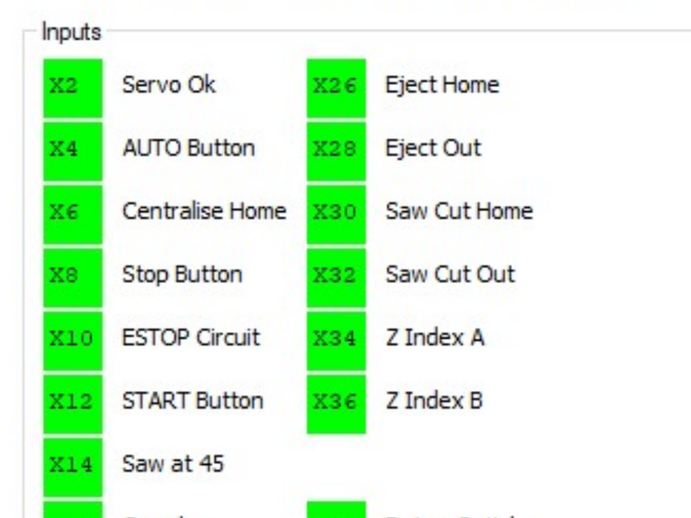
Accessing IO page
The I/O page is accessed by pressing the Service button on the Settings tab. This displays a form with the Inputs and Outputs displayed as below

Inputs are the feedback from sensors, buttons and switches and have a code beginning with "X". The state of an input is displayed as:
Green - Input inactive
Red - Input active
Outputs are used to control valves or other electrical devices on and off and have a code beginning with "Y". The output is toggeled on and off by touching the square on the screen relating to the output number.
Green - Output off
Red - Output On
Outputs In Detail
| Output No | Name | Function |
| Y6 | Side Clamp | Brings in the guiding clamp under low pressure. |
| Y8 | Load Clear | Keeps the loading material 10 mm away from the backfence. This stops the material getting jammed. |
| Y10 | Clamp Position | Brings clamps to a central position when cutting wide sections. |
| Y14 | Eject | Extracts the cut piece from the right hand side of the saw. |
| Y16 | Mullion Centre | Centres up the pivot point of the saw blade on the material. Also brings the clamps into a central position. |
| Y18 | Saw Cut | Saw blade rises. |
| Y20 | Saw to 90 | Saw blade to 90-degree position. |
| Y22 | Saw to 135 | Saw blade to 135-degree position. Note: Y20 must also be on to achieve this. |
| Y24 | Next Bar | Activates material loading crossfeed belts. These are on a ratchet mechanism, so can only go one way. |
| Y26 | Eject Clamp | Clamp on right hand side of blade. |
| Y28 | Eject Push | Pusher arm for clearing cut material out of the way. |
| Y30 | Z Roller | Brings in support for Z-sections to prevent them tipping over. |
| Y32 | Saw Clamp | Clamp on left hand side of blade. |
| Y34 | Clamp HIP | Activates High pressure clamping on the saw clamp. The low pressure helps to keep the material from tipping when it is pushed through. |
| Y36 | Blowers | Air Blowers to prevent swarf build-up. |
| Y40 | Z-turret Stop | Rotates the Z-turret stop through up to 360 degrees. |
Y6 - Side Clamp
The side clamp is brought in when cutting mitres. It holds the material square against the backfence when it is being pushed through. It is pressure controlled with a regulator to give friction to the pusher arm. This friction is needed because the arm does not grip the material, the friction stops the material running away when the arm decelerates.
Adjustment
Pressure regulator PR1 adjusts the amount of clamp pressure and hence friction.
Damper D1 regulates the speed that the clamp comes across.
Home Position
Clamp is towards front of machine, i.e. Clamp off.
Y8 - Load Clear
When the auto loader loads the material, it was observed that the material would sometimes rest against the backfence. When it was pushed, the friction would sometimes be too great and the pusher would stall. To overcome this problem, the Load Clear cylinders were added to give a false backfence 10 mm away from the real one.
The cylinders come out as the material is loaded, and retract when the pusher arm starts to push. This gives the material a generous amount of clearance as it is pushed through.
Home Position
Retracted.
Y14 - Eject
After the second saw cut, the profile is cut to length and must be extracted out of the way on to the outfeed table. This is the function of eject.
Home Position
Left
Y16 - Mullion Centre
This controls the most innovative part of the saw - the centring mechanism. Using the side clamp assembly, this output Centres the pivot point of the saw to the exact centre of the material in the machine. This means that in order to hold the material, the machine must be using Y6 the side clamp, or Y16 mullion centre. Y6 is used for mitre cuts, where the saw pivot point is a set distance from the backfence, Y16 is used when cutting arrowheads, where the pivot point must be in the exact centre of the material.
In addition, the clamping position is changed hence this output also controls the clamp positioning cylinders.
Adjustment
Pressure regulator PR2 controls the pressure applied to the side clamp, and so the friction. It should be set to roughly the same as PR1, as it does the same job.
Velocity damper D1 controls the speed that the side clamp moves across, described under ‘Y6’.
Home Position
Side clamp is towards front of machine (i.e. clamp off, not centralised).
Clamp positioners are towards back of machine.
Y18 - Saw Cut
The cutting head up / down movement.
Adjustment
Velocity damper D2 controls the speed of the cut. There must be a balance between the fastest cutting speed and the quality of the cut. Quality of the cut unfortunately deteriorates with cut speed.
Y20 Y22 - Saw to 90 and Saw to 135
Used for positioning the head to 45°, 90° and 135°. Two cylinders are mounted back to back to give 4 possible permutations, allowing 3 positions:
| Y20 | Y22 | Position |
| Off | Off | 45° |
| On | Off | 90° |
| Off | On | Unpredictable - not used |
| On | On | 135° |
Adjustment
Flow control valves, mounted on the ports of the cylinders, control the speed of the rotation. Ensure all cylinders are adjusted to the same position.
Home Position
Head at 45°.
Y24 - Next Bar
Activates the autoloading crossfeed belts. Two cylinders are used side by side to give the required force to move the belts when they are fully laden with material.
Home Position
Retracted.
Y26 - Eject Clamp
Activates the clamp attached to the ejector mechanism on the right hand side of the saw blade.
Adjustment
A flow restrictor restricts the rate at which the clamp comes down, so that it will not damage the material.
Home Position
Clamp off.
Y28 - Eject Push
Activates the pusher bar that pushes the last cut piece out of the way of the ejector mechanism. These cut pieces then stack up on the outfeed table.
Adjustment
The speed of the push is controlled with a flow restrictor.
Home Position
Pusher is back.
Y30 - Z Support
Activates the Z support blocks. These blocks emerge from the backfence when Z sections are being cut. They act to support the section and prevent it from twisting over when the side clamp comes in.
Home Position
Retracted.
Y32 - Saw Clamp
Activates the clamp on the left hand side of the saw blade.
Adjustment
A flow restrictor restricts the rate at which the clamp comes down, so that it will not damage the material.
Home Position
Clamp off.
Y10 - Clamp Pos
Activates the clamp positioners to come out to the central position. This was found to be useful when wide sections are used, to give them more support. The wide section limit is defined as on of the parameters - widewidth.
Home Position
Retracted.
Y34 Clamp HIP
Clamp high / low pressure switch. When the material is pushed though, a pressure is needed on the top to prevent some Z sections from rolling over. The saw clamp does this (Y32) and the pressure is alternated between full saw clamp pressure and low feed pressure by this output. A 3 port 2 position valve uses air to switch another 3/2 valve to make the switch. The air is amplified like this because at low pressure, the solenoid pilot cannot work.
Y36 Blowers
Two Air blowers situated on the chute.
Y40 Z-Turret Stop
This indexes the Z-turret stop around ¼ turn with each press of any key.
Draft
 Français
 English
 Deutsch
 Español
 Italiano
 Português