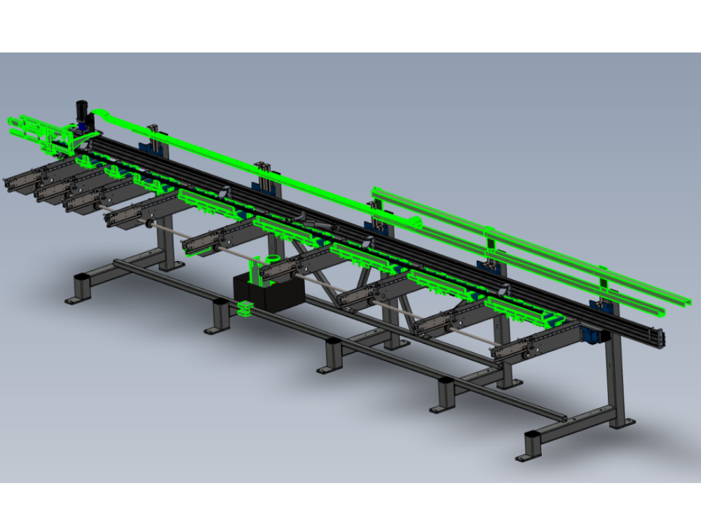
Second page of instructions To complete R0015278 assembly mounting

Difficulté
Moyen
Durée
1 heure(s)
Sommaire
- 1 Introduction
- 2 Étape 1 - This is section two
- 3 Étape 2 - Unless otherwise stated
- 4 Étape 3 - Clean threads
- 5 Étape 4 - Mount 1st take up arm
- 6 Étape 5 - Mount 2nd,3rd and 4th arms
- 7 Étape 6 - Mount channel bars
- 8 Étape 7 - Mount cylinder assembly
- 9 Étape 8 - Adjust cylinder position on hepco beam
- 10 Étape 9 - Adjust take up arms
- 11 Commentaires
Introduction
Tools Required
Standard Hex key set
Standard spanner set
300 mm rule
1000mm rule
Parts Required
D0008288 Takeup Pad Left (D7339) (Wet/P F Matt) x 1
D0015583 Take Up Beam Joiner x 1
D0015598 Datum Flag: Saw Infeed x 1
D0015717 Energy Chain Angle Bracket Lower x 5
D0015718 Energy Chain Angle Bracket Upper x 2
D0015718B Energy Chain Angle Bracket Double Deck x 3
D0015720 Carriage Bracket x 1
D0015721 Energy Chain Tray Deep Long x 1
D0015723 Energy Chain Tray Shallow x 1
D0015724 Energy Chain Tray Deep x 2
D0015725 Energy Chain Tray Shallow Medium x 1
D0015742 Takeup Pad Right ZX5 x 1
D0015862 Energy Chain Tray Deep Long x 1
E0000336 Sensor: M8; 2mm, PNP N/O, M8 conn x 1
R0015011 Bench Assemble Gripper
R0015063 Bench Assemble Roller Tables
R0015096 Bench Assemble Transfer Drive Assembly
R0015101 Bench assembly take up assembly
R0015286 Bench Assemble X axis components and energy chainÉtape 2 - Unless otherwise stated
Use loctite 243 on all fasteners
Use Loctite 572 on all threaded pneumatic connections
Pen mark all fasteners to show finalised

Étape 3 - Clean threads
Clean threads in parts
D0015742 Takeup Pad Right ZX5 x 1
D0008288 Takeup Pad Left (D7339) (Wet/P F Matt) x 1


Étape 4 - Mount 1st take up arm
Use 4 off F0000299 M6 d nuts and 4 off M6 x 20 socket caps to mount takeup arm at position shown
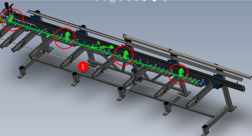
Étape 5 - Mount 2nd,3rd and 4th arms
Mount remaining 3 take up arms as shown using fasteners stated in previous step

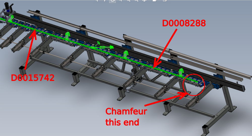
Étape 6 - Mount channel bars
Mount bars
D0015742 Takeup Pad Right ZX5 x 1
D0008288 Takeup Pad Left (D7339) (Wet/P F Matt) x 1
Use M6 x 25 socket caps and penny washers to secure
Join together with
D0015583 Take Up Beam Joiner x 1
Use M6 x 30 socket caps 4 off
Chamfeur to positioned as indicated


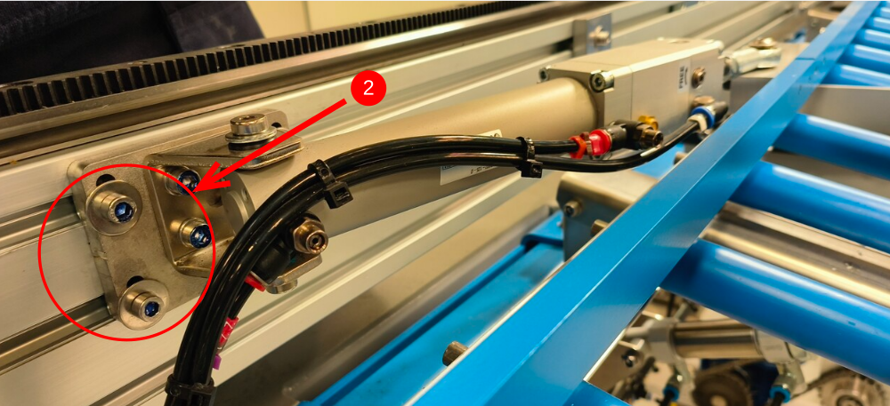
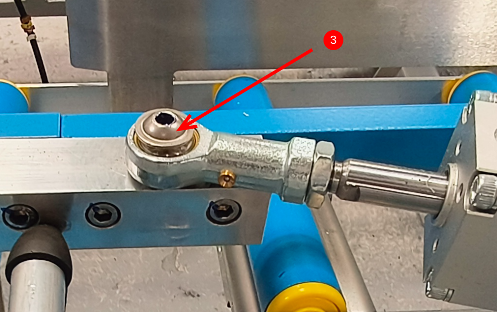
Étape 7 - Mount cylinder assembly
1 Over ride lock function so piston on cylinder can move freely
2 Mount in position shown . Do Not apply adhesive to these fasteners yet .
use M6 x 20 socket caps and penny washers to secure
3 Attach rod end using M8 x 25 Flanged button head

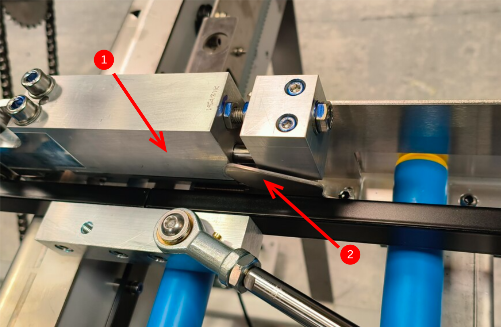
Étape 8 - Adjust cylinder position on hepco beam
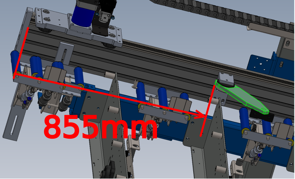
1 Bring gripper to position shown
2 Add 2.5mm shim between gripper and channel bar as indicated
3 Adjust position of cylinder mount so fully extended cylinder piston leaves the 2.5mm gap between gripper and channel bar

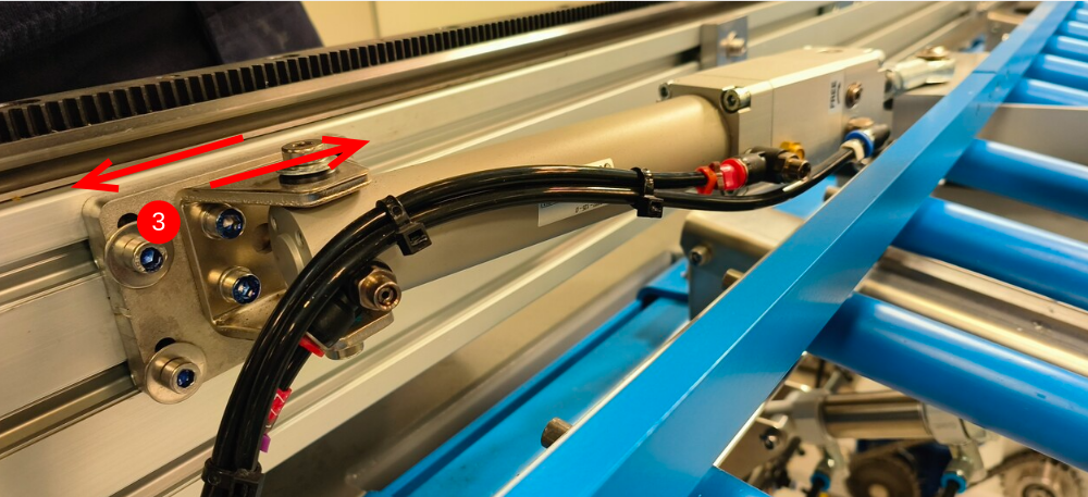
Étape 9 - Adjust take up arms
1 Repeat above step at take up arm positions to set channel bar parallel to gripper
Use slots in nylon blocks to adjust position
If more movement is required . take up arm mounting point on hepco can be adjusted in same directions as previous step
Draft
 Français
 English
 Deutsch
 Español
 Italiano
 Português