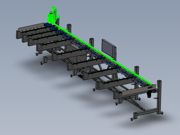
Instructions to mount pre built assemblies to frame
Introduction
Tools Required
Standard hex key set
Parts Required
D0015432 Spacer: Ø25.4 x 100mm (12.7mm ID) x 10
D0015479 Sensor Mount Rail 1450 mm Long x 4
D0015480 Sensor Mount Rail 825 Long x 1
F0000299 T Nut Sub Insert M6 (Fat) x 16
R0015030B Bench Assembly Loader Wheel
R0015080 Bench assemble sensor rail
R0015271 Mount buffer bars ( pre fitted to frame )
R0015351 Mount monitor to frame (pre fitted to frame)Étape 1 - Unless otherwise stated
Use loctite 243 on all fasteners
Use Loctite 572 on all threaded pneumatic connections
Pen mark all bolts to show finalised
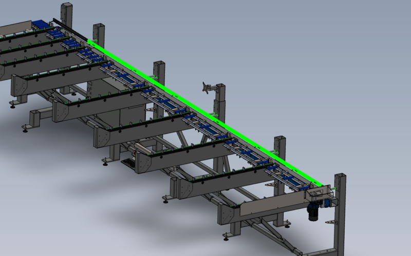
Étape 2 - Attach sensor rail 1
Use M10 x 120 socket caps to secure sensor rail parts to frame
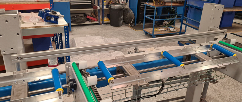
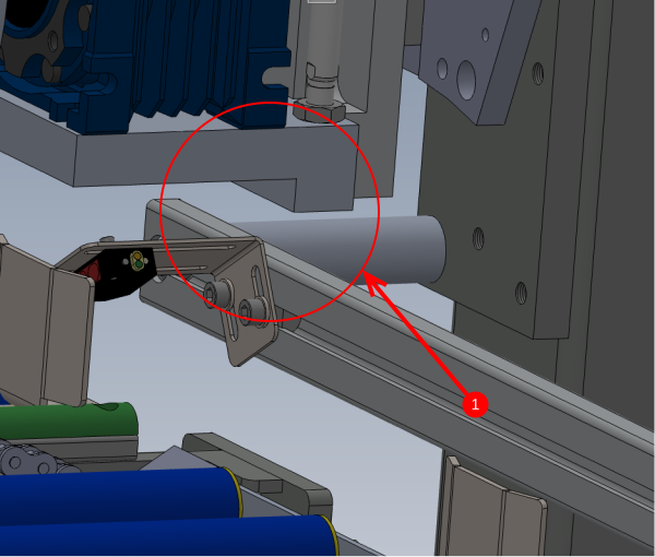
Attach D0015480 Sensor Mount Rail 825 Long with 2 off D0015432 Spacer: Ø25.4 x 100mm (12.7mm ID)
Étape 3 - Attach sensor rails
Use M10 x 120 socket caps to secure sensor rail parts to frame
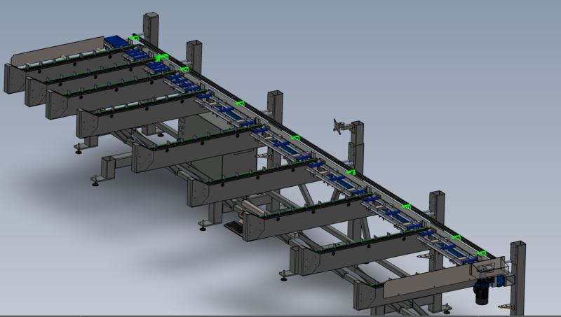
Attach 4 off D0015479 Sensor Mount Rail 1450 mm Long with 8 off D0015432 Spacer: Ø25.4 x 100mm (12.7mm ID)
Étape 4 - Mount sensors
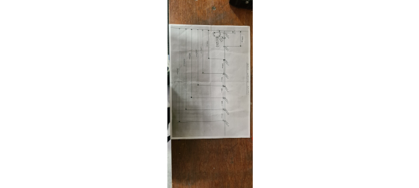
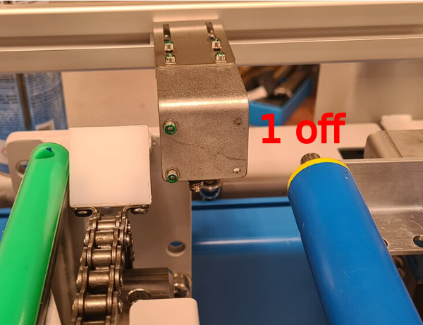
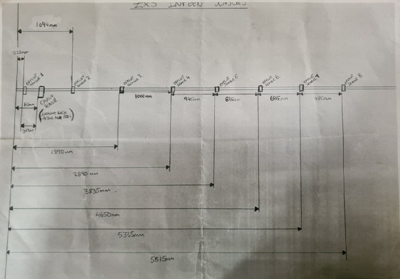
Mount sensors from assembly R0015080 with F0000299 M6 D nuts and M6 x 12 socket caps with A form washers
Use Drawing shown for positions , and images for orientation
Étape 5 - Mount Loader wheel assembly
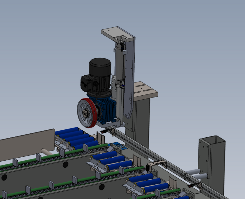
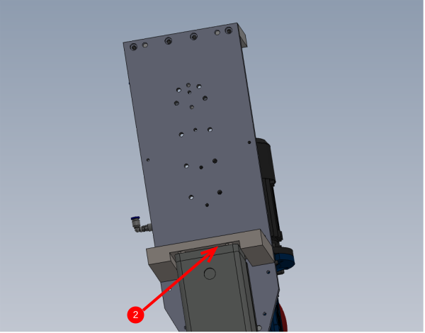
Mount loader wheel assemble to frame Using socket caps (size required)
Quality check
1 When loader wheel pulley is in its lowest position it must not hit the sensor rail assembly. If contact is evident follow step 2
2 Use Washers as spacers ( size required ) to lift the assembly up from the frame mounting point and create clearance between the loader wheel and the sensor rail
Draft



 Français
 English
 Deutsch
 Español
 Italiano
 Português