instructions for installing main drive shafts to support arm assembly

Difficulté
Moyen
Durée
2 heure(s)
Introduction
Tools Required
Standard Hex key set
Parts Required
Previously assembled parts from R0015287 Bench Assemble Shafts, Bearings and Pinions
B0001100 x 12
B0001153 x 1
B0001165 x 1Étape 1 - Unless otherwise stated
Use Loctite 243 on all fasteners
Use Loctite 572 on all threaded pneumatic connections
Pen mark all bolts to show finalised

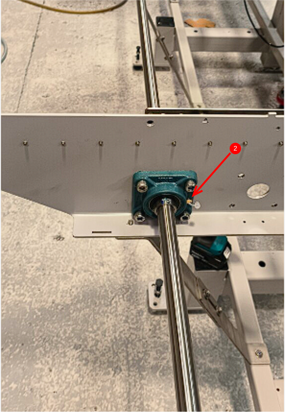
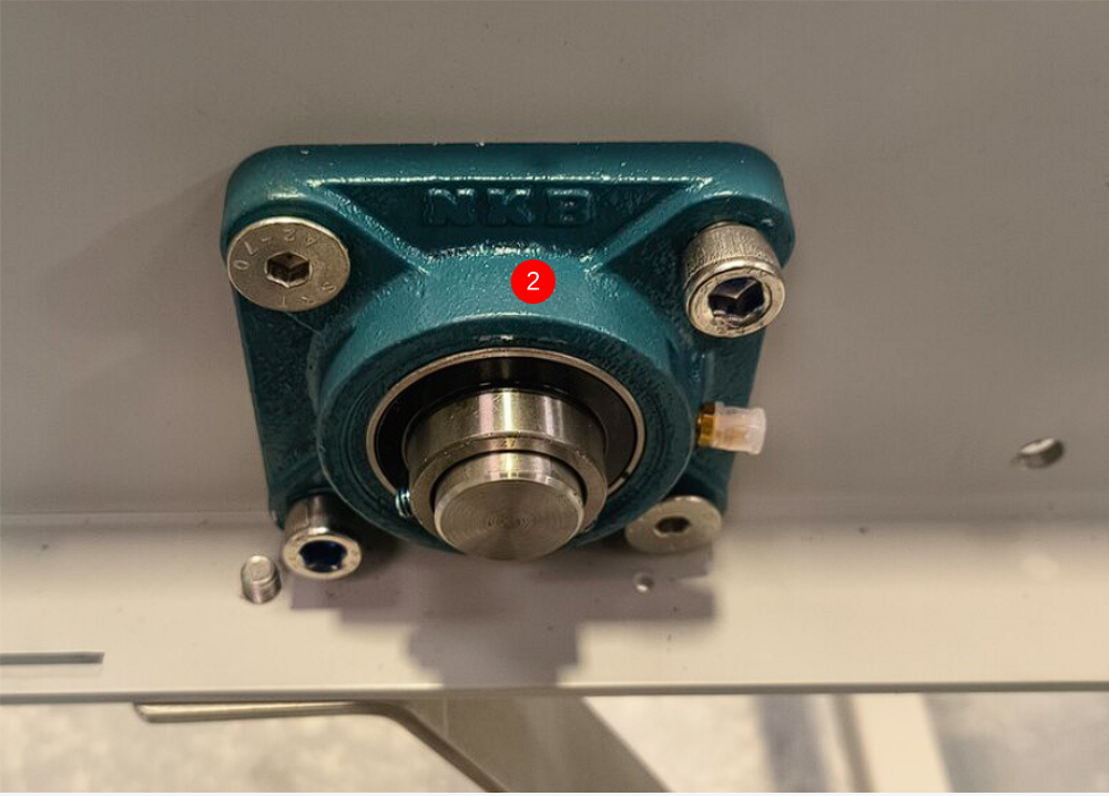
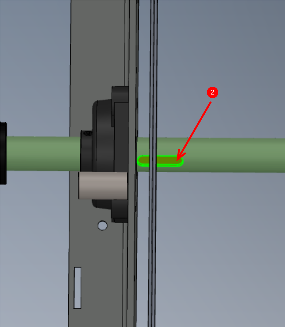
Étape 2 - Bearing position Clarification
1 Bearings should be located as shown on each arm
2 Grease nipples to face as shown

Étape 3 - Attach Bearings
1 Use 2 off M10 x 40 Countersunk bolts to centralise position of bearing block
2 Add 2 off M10 x 20 socket cap and fix in two holes indicated and tighten.
3 Replace M10 counter sunk bolts with another 2 off M10 x 20 socket caps
repeat for all bearing mounting positions


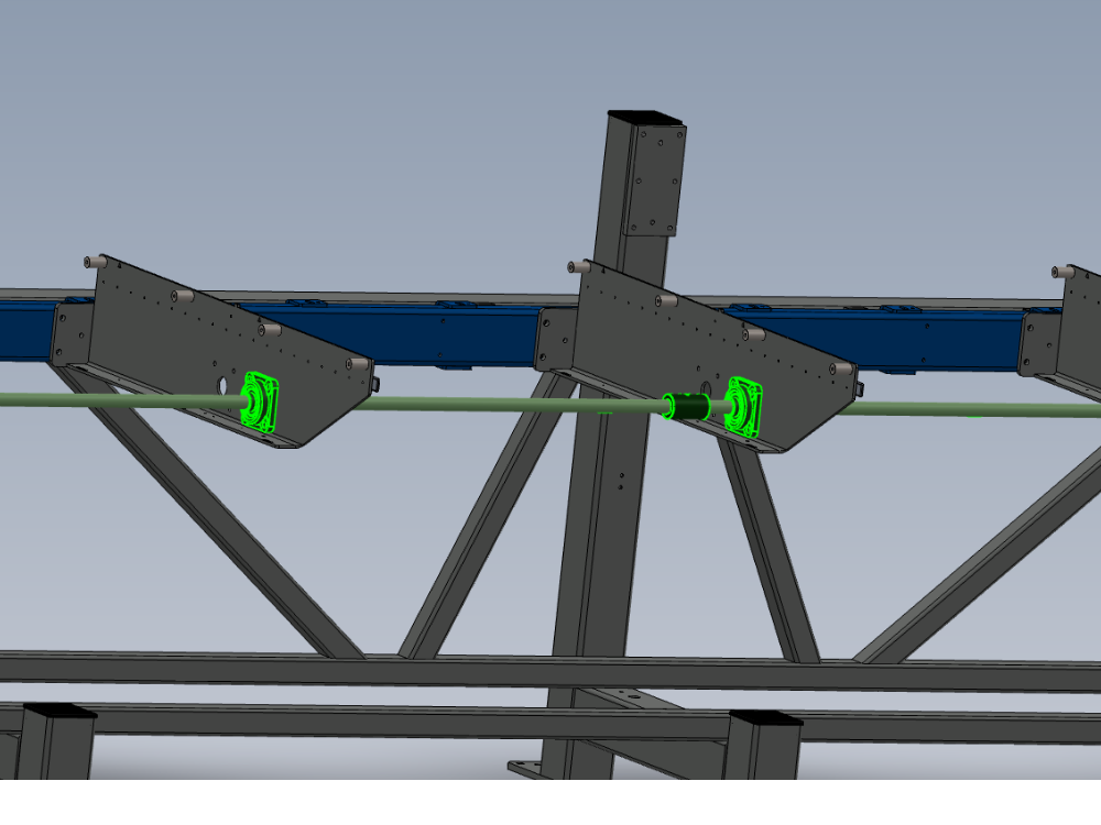
Étape 4 - Location of shafts
1 Shafts need to be correctly orientated
2 Each arm should have a key positioned as shown for drive pinions
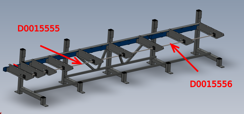
Étape 5 - Fit shafts and pinions
1 Shafts should be slid through bearing blocks to install. Drive pinions should be added to shaft between each arm as the shaft is fitted.
2 B0001165 2 off drive sprockets will also require adding to shafts as they are fitted . See images for location
3 B0001165 should be orientated as shown
Draft
 Français
 English
 Deutsch
 Español
 Italiano
 Português