Pre Assembly of drive cylinders with sensors

Difficulté
Moyen
Durée
2 heure(s)
Sommaire
- 1 Introduction
- 2 Étape 1 - Mount single plunge home sensor
- 3 Étape 2 - Attach air fittings to single plunge cylinders
- 4 Étape 3 - Attach sensor bracket to Single plunge cylider
- 5 Étape 4 - Fit single out sensor
- 6 Étape 5 - Attach air fittings to double plunge cylinders
- 7 Étape 6 - Mount double plunge cylinder sensors
- 8 Étape 7 - Mount magnet to cylinder anchor
- 9 Commentaires
Introduction
Tools Required
Standard spanner set
Small screwdriver set
Reed switch test box
Araldite 2 part adhesive
Parts Required
D0015540 sensor bracket x 8
P0000488 Sensor x 8
P0001098 elbow adapter x 12
P0000238 6mm elbow x 8
P0001198 6mm flow elbow x 8
P0000459 4mm elbow x 4
P0000629 4mm flow elbow x 4
P0001200 cylinder x 8
P0001201 cylinder x 4
P0001047 reed switch x 16
D0007630 cylinder anchor x 8
M0001170 magnet x 8
Étape 1 - Mount single plunge home sensor
8 off
1 Remove OEM sensor locking nut from sensors P0000488
2 Label sensors at trailing end SH
3 Use m4 x 6 button heads and attach sensor to D0015540 as shown
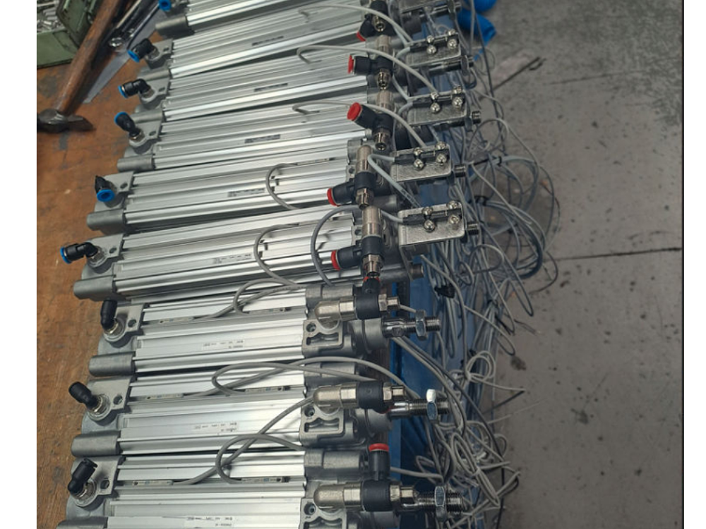
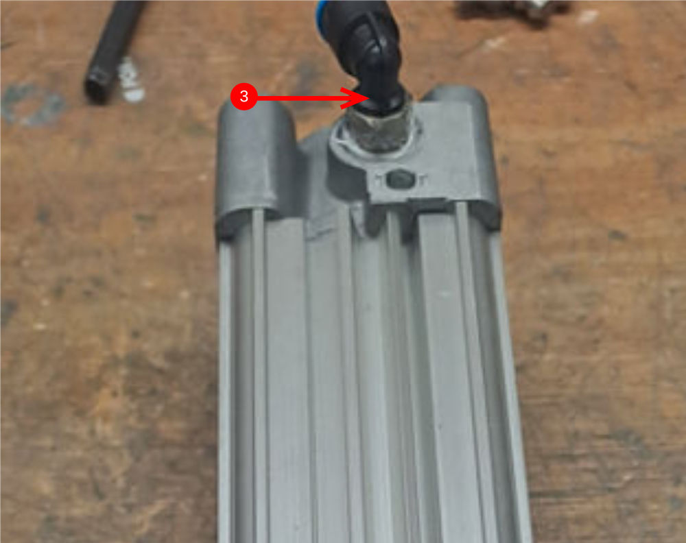
Étape 2 - Attach air fittings to single plunge cylinders
8 off P0001200 cylinder
Use Loctite 572 on all air fittings
1 Attach P0001098 elbow as shown
2 Attach P0001198 elbow
3 Attach P0000238 elbow
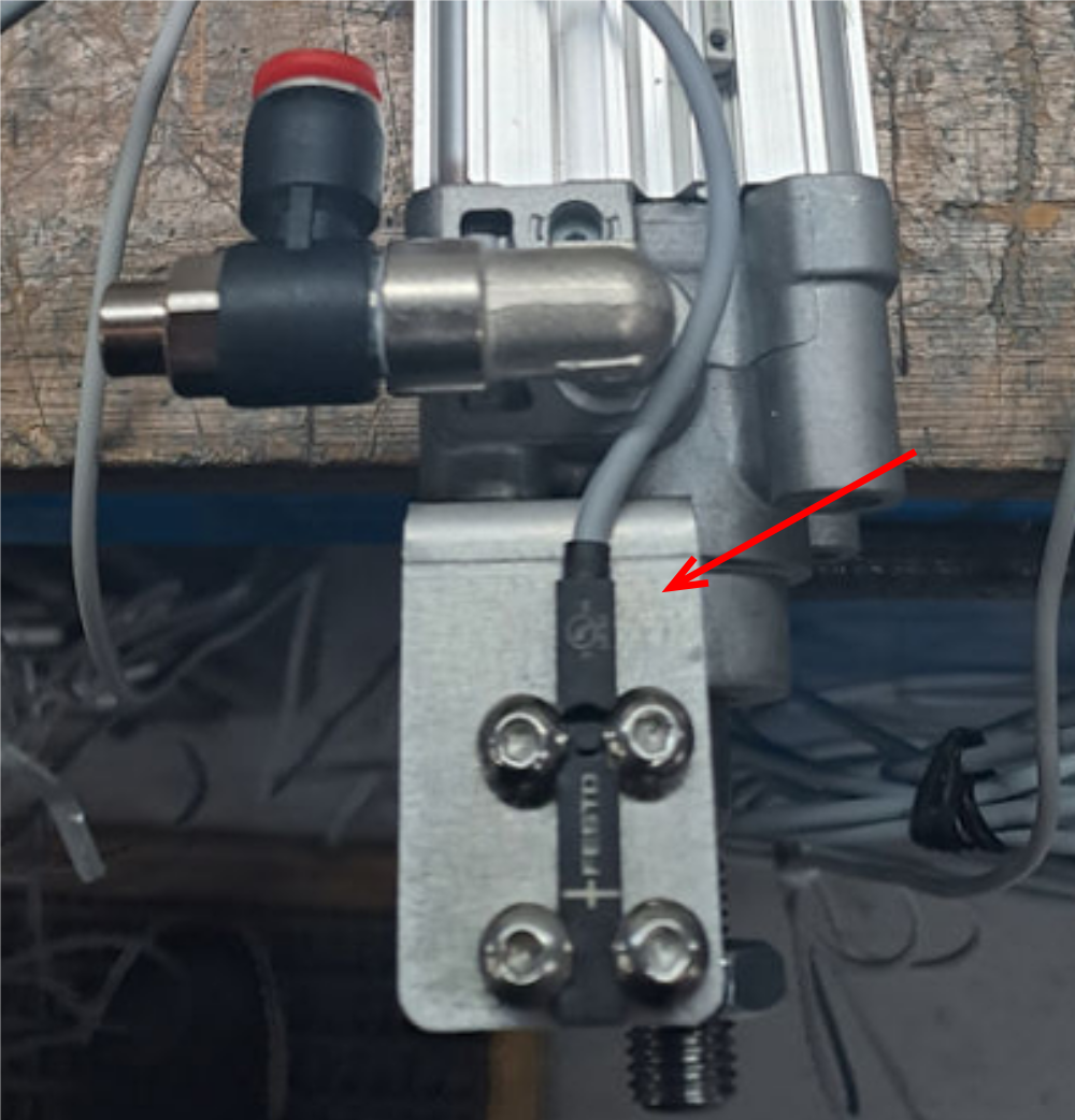
Étape 3 - Attach sensor bracket to Single plunge cylider
8 off
Use 2 off m6 x 16 socket caps to attach sensor bracket to cylinder
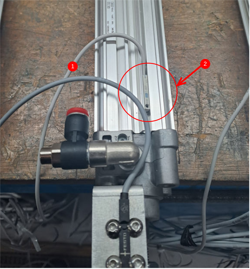
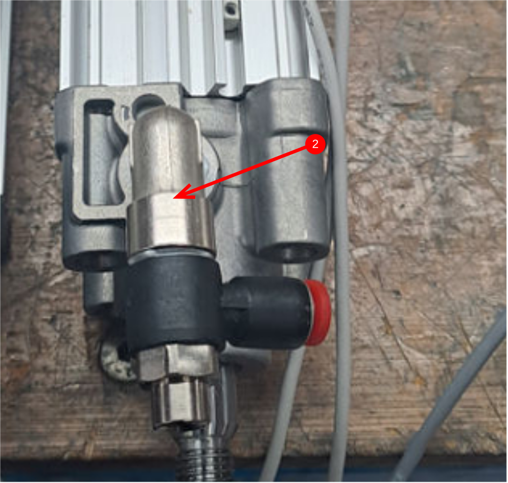
Étape 4 - Fit single out sensor
8 off
1 label 8 off P0001047 sensor SO at connection end
2 Use test box and connect sensor and set position on cylinder with piston extended out of cylinder
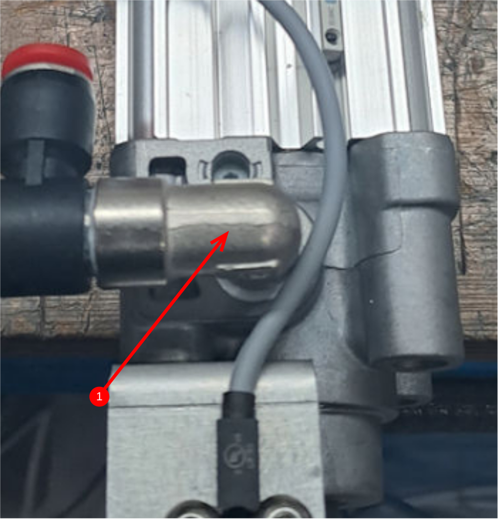
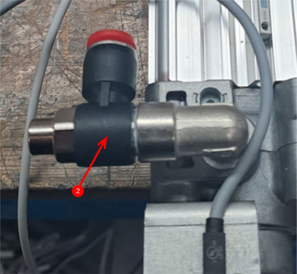
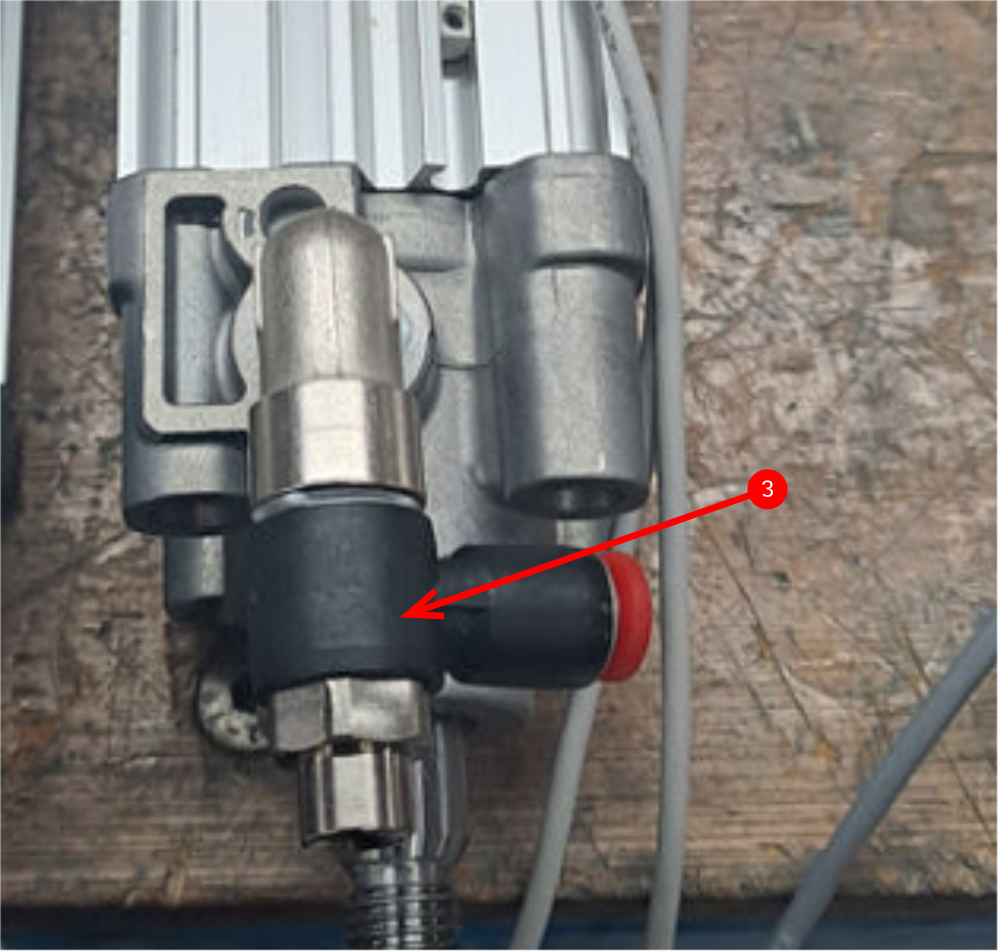
Étape 5 - Attach air fittings to double plunge cylinders
Use Loctite 572 on all air fittings
4 off Cylinder P0001201
1 Attach P0000459 4mm elbom
2 Attach P0001098 elbow
3 Attach P0001198 flow regulator elbow

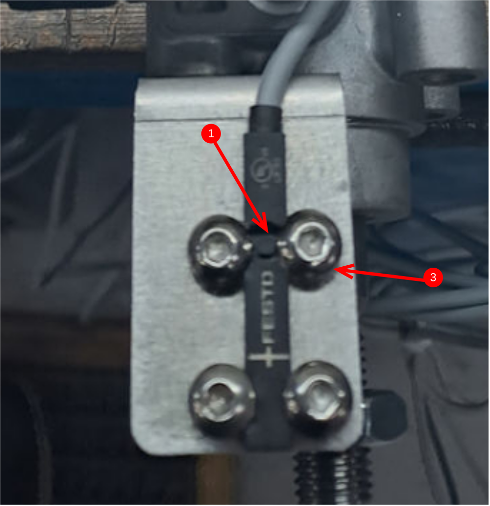
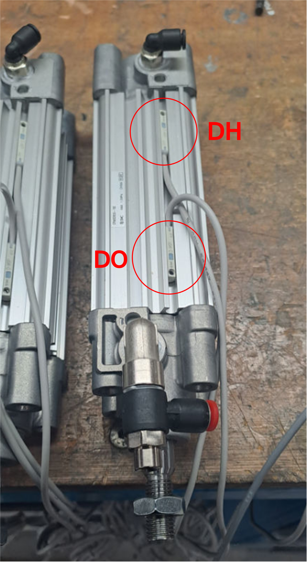
Étape 6 - Mount double plunge cylinder sensors
Mark 4 off sensors P0001047 at connection end DO
Mark 4 off sensors P0001047 at connection end DH
Use test box and set reed switches in position on cylinders orientated as shown in picture
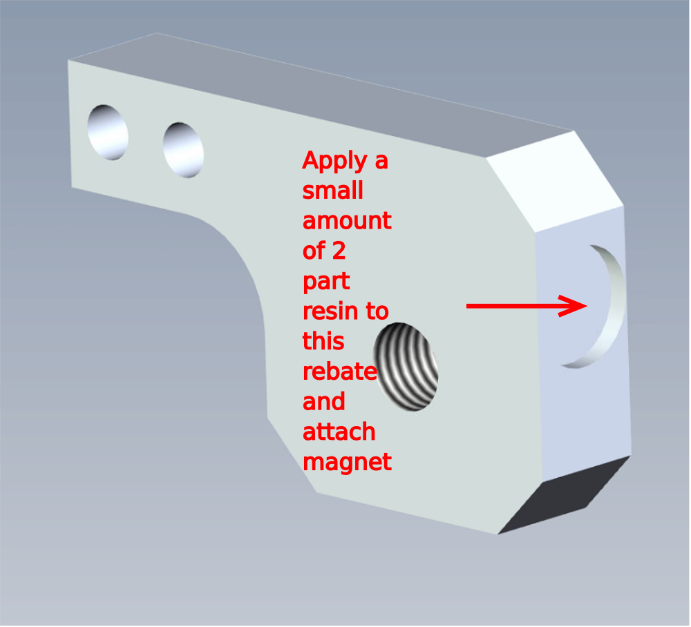
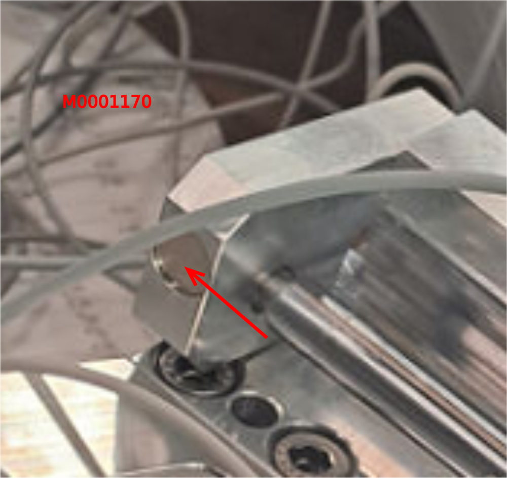
Étape 7 - Mount magnet to cylinder anchor
M0001170 magnet must have additional adhesive applied to be adequately attached to D0007630 cylinder anchor
Draft
 Français
 English
 Deutsch
 Español
 Italiano
 Português