Instructions for correct assembly of Notching gearboxes


Difficulté
Difficile
Durée
1 heure(s)
Sommaire
- 1 Introduction
- 2 Étape 1 - Q/C Bevel Gears
- 3 Étape 2 - Q/C Hardened parts
- 4 Étape 3 - Degreasing of components
- 5 Étape 4 - Assemble 1st bevel gear assembly
- 6 Étape 5 - Fit key and spacer
- 7 Étape 6 - Fit bevel gear and top bearing
- 8 Étape 7 - Fit Castle nut
- 9 Étape 8 - Fit 1st bevel gear assembly to housing
- 10 Étape 9 - Check rotation of assembly.
- 11 Commentaires
Introduction
For longevity and correct running , it is imperative these units are assembled to the correct tolerances and assembled in the way detailed by this procedure
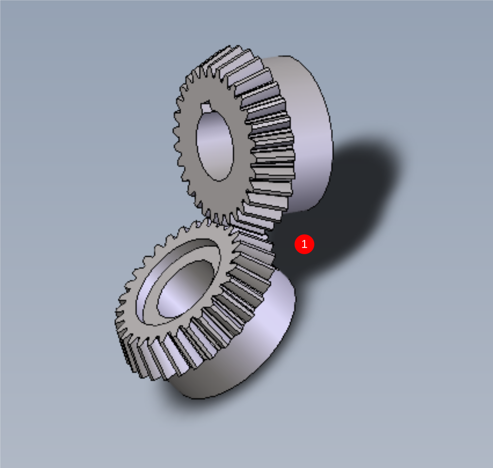
Étape 1 - Q/C Bevel Gears
1 Supplied drive gears should be inspected for the following
- Evidence of damage to drive gear teeth, such as burrs or impact points.
- Cleanliness check. There should be no contaminants on the gears
Report any damage to gears through NCR system to log and retrieve replacement gears
Any rust/ surface contaminate should be removed with a wire brush
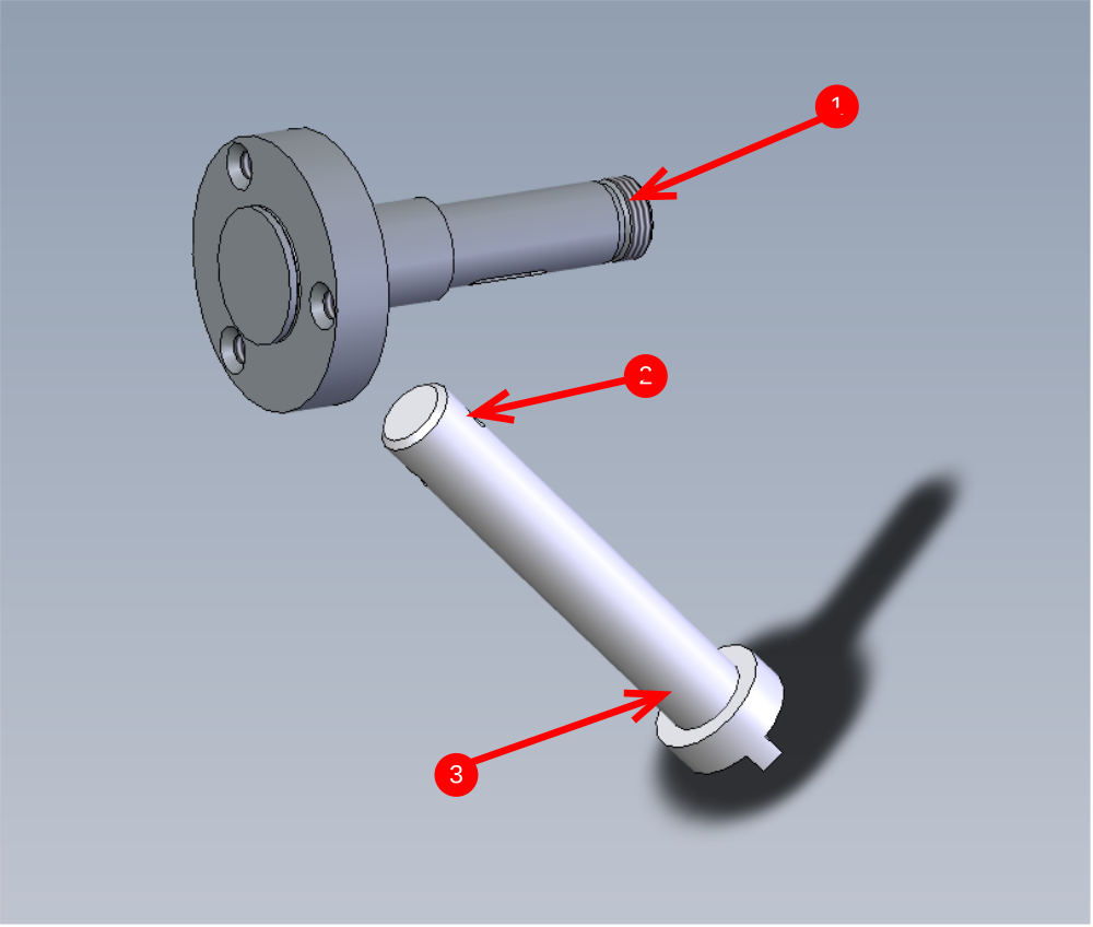
Étape 2 - Q/C Hardened parts
Drive shafts should be inspected for the following
1 Damage to indicated thread
2 Presence of burrs on roll pin hole
3 Contaminates from hardening
Damage to thread should be reported by NCR system and replacement sourced
Burrs should be removed by file
Contaminates should be removed with Scotch brite pad
Étape 3 - Degreasing of components
It is vital for correct function that all the shown components are thoroughly degreased before assembly .
To do this, wash all parts with FE10 solvent spray and dry with airline.


Étape 4 - Assemble 1st bevel gear assembly
1 Check plate D0008158 for any number etching. If it is present it should always be assembled with the etching to be on the face shown
2 Mount plate over drive dog, and then press bearing onto shaft to encapsulate the plate. When the bearing is fitted the plate should still be free to move in the gap left

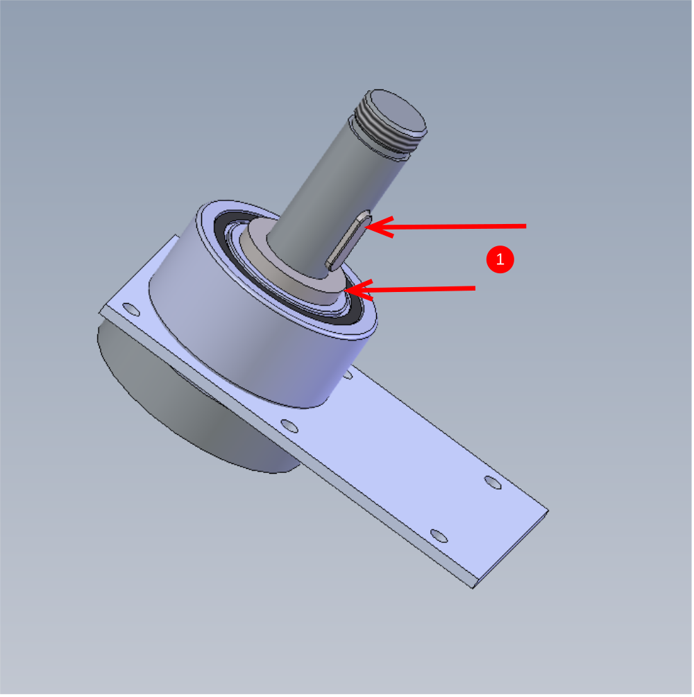
Étape 5 - Fit key and spacer
Fit Spacer on top of bearing and then fit key to keyway on shaft
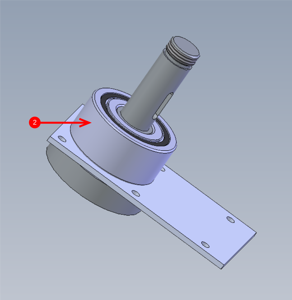
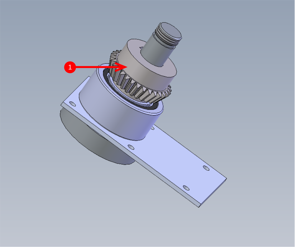
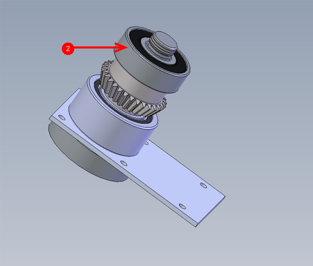
Étape 6 - Fit bevel gear and top bearing
1 Fit bevel gear onto assembly orientated as shown
2 Fit Bearing to top of shaft as indicated remembering to check fit of bearing
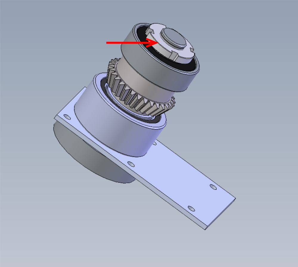
Étape 7 - Fit Castle nut
Castle nut will need fair tension to correctly hold the assembly together
It is best to hold the assembly in a vice to enable the nut to be tensioned correctly.
Use loctite 243 on castle nut and use correct castle nut spanner to tension.
Ensure castle nut is fitted in the orientation shown. Larger flat face should facing outwards, smaller face should contact bearing
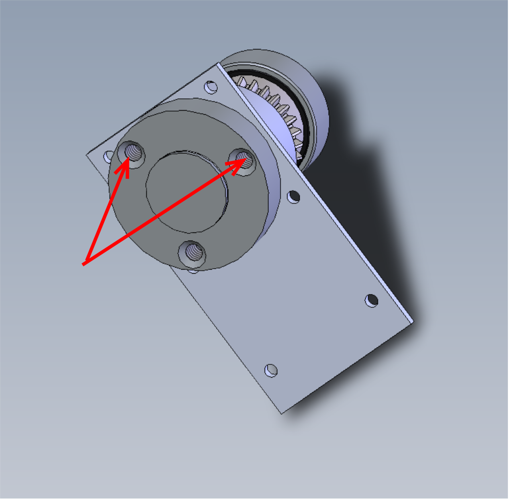

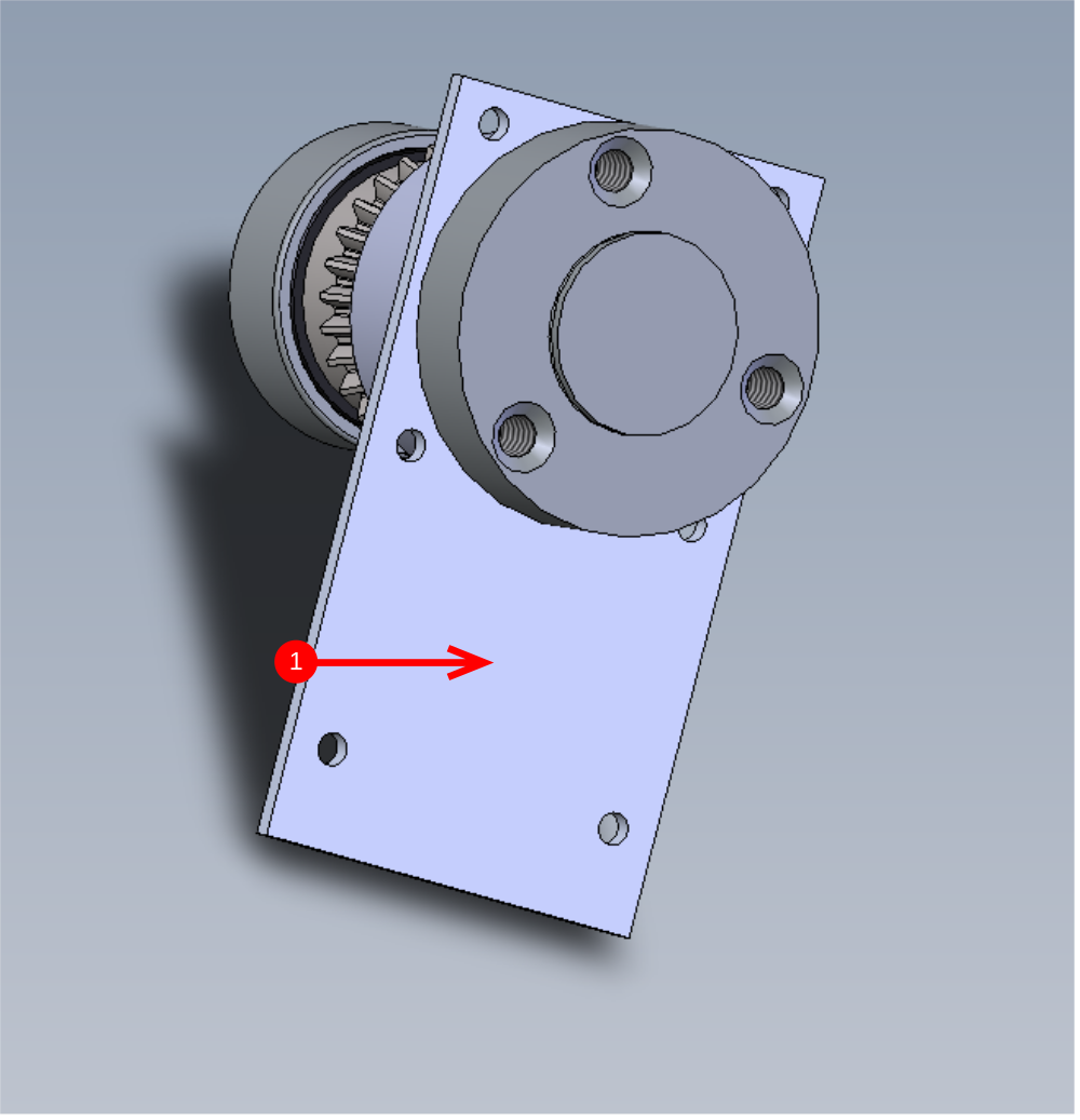
Étape 8 - Fit 1st bevel gear assembly to housing
1 Add 3 match head sized drops of bearing fit to indicated bore and smear around
2 Add 3 match head sized drops of bearing fit to indicated bore and smear around
3 Insert by hand 1st bevel gear assembly into bore, there should be slight resistance but no more pressure than hand pressure should be required. 4 Ensure assembly is pushed fully in then captivate with 6 off m3x10 cap head bolts with no washers with loctite 243. Once tight pen mark bolts to shown completed


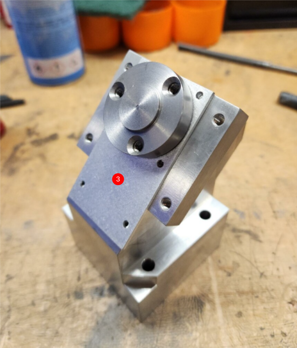

Étape 9 - Check rotation of assembly.
Once all fitted rotation of assembly in housing should be checked . Rotation should be smooth and consistent with no high spots or lumps

Draft
 Français
 English
 Deutsch
 Español
 Italiano
 Português