Instructions to bench assemble gripper
Sommaire
- 1 Introduction
- 2 Étape 1 - Fit bushes and bearings
- 3 Étape 2 - check fitment of D0015084 shafts
- 4 Étape 3 - Assemble load switch plate
- 5 Étape 4 - Assemble cylinder
- 6 Étape 5 - Assemble grip pin assembly
- 7 Étape 6 - Mount grip pin assembly to grip slide
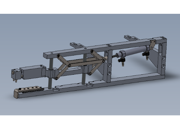
- 8 Étape 7 - Assemble main frame of gripper assembly
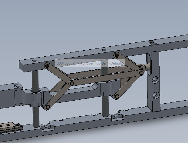
- 9 Étape 8 - Fit link bars to assembly
- 10 Étape 9 - Fit Cylinder assembly
- 11 Étape 10 - Add mounting brackets
- 12 Commentaires
Introduction
Étape 1 - Fit bushes and bearings
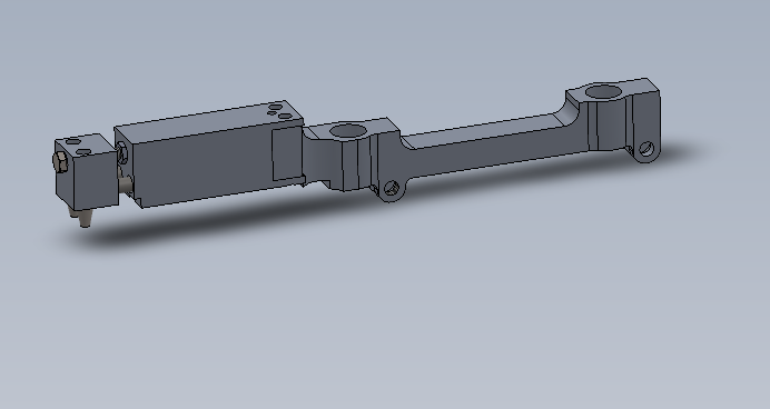
Fit bushes to gripper link bars
Fit bearings to gripper slide and grease
Étape 2 - check fitment of D0015084 shafts
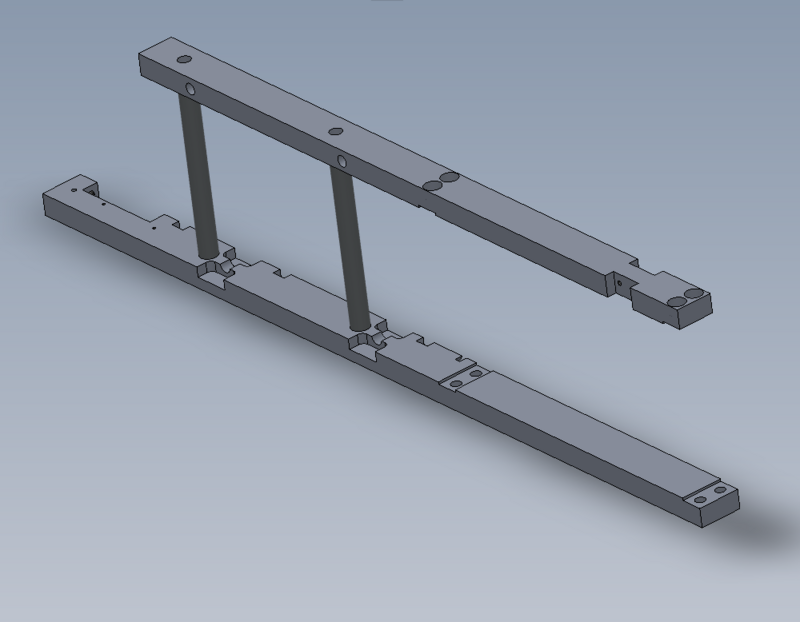
check shafts fit correctly into bores of D0015082 gripper bottom bar and D0015083 gripper upper bar
Étape 3 - Assemble load switch plate
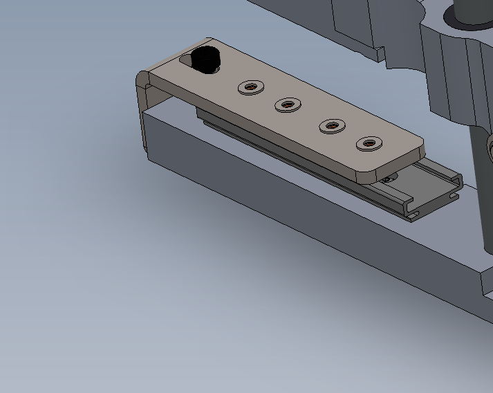
Check for correct type of sensor- Fit sensor Fit cable and cleats
Fit load switch assembly
Quality checks?
Étape 4 - Assemble cylinder
Fit air fitting to cylinder
Mount reed switches and bands to cylinder
Correct orientation of bands required
Étape 5 - Assemble grip pin assembly
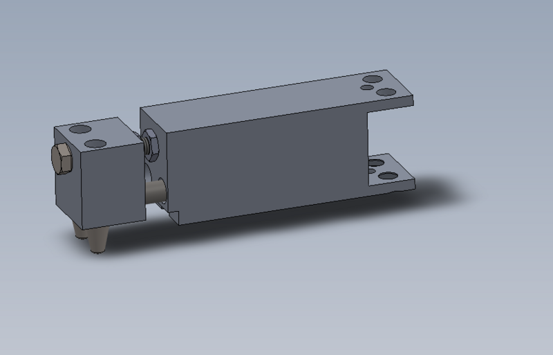
Fit bushes to body
ensure dowels fit correctly in nose
Correct gap set by set bolt and half nuts
correct length of bolt ?
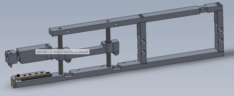
Étape 7 - Assemble main frame of gripper assembly
correct bolts
how to position D0015085 blocks to top and bottom bars
Check top and bottom bars are parallel
Check grip slide moves freely
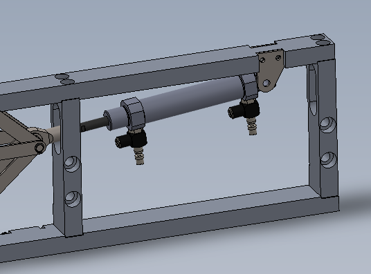
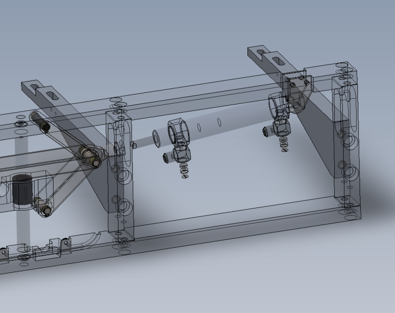
Étape 9 - Fit Cylinder assembly
Fit assembled cylinder unit to gripper frame
Bolts to use and setting for rod end on cylinder shaft
Draft
 Français
 English
 Deutsch
 Español
 Italiano
 Português