Alignment and mounting procedure for main x axis drive rail

Difficulté
Difficile
Durée
6 heure(s)
Sommaire
- 1 Introduction
- 2 Étape 1 - Mount Levelling jigs to blue section
- 3 Étape 2 - Level jigs
- 4 Étape 3 - Align Jigs
- 5 Étape 4 - Position Hepco rail
- 6 Étape 5 - Assemble carriage plate and fit to hepco rail
- 7 Étape 6 - Checking Levels and adjusting
- 8 Étape 7 - Laser checks on straightness
- 9 Étape 8 - Mounting brackets
- 10 Étape 9 - Remove set up jigs
- 11 Commentaires
Introduction
Alignment and check procedure for mounting of hepco rail To main frame
Parts required
B0001102 hepco rail
D0015492 5 off vertical adjustment plate
D0015493 5 off Lateral adjustment plate
D0015072 1 off Carriage Plate
B0000184 journal wiper 4 off
B0000185 journal 2 off
B0000186 journal 2off
Hepco Levelling Jig
Hepco rail v block jigs
Hepco rail Drive rack pitching jigÉtape 1 - Mount Levelling jigs to blue section
Locations of jigs required
mounting method
Étape 2 - Level jigs
Levelling jigs
1st level jigs individually
2nd level jigs to each other
Étape 3 - Align Jigs
Use wire to align jigs to each other
Double checks ensure levels are correct after wire alignment
Q/C
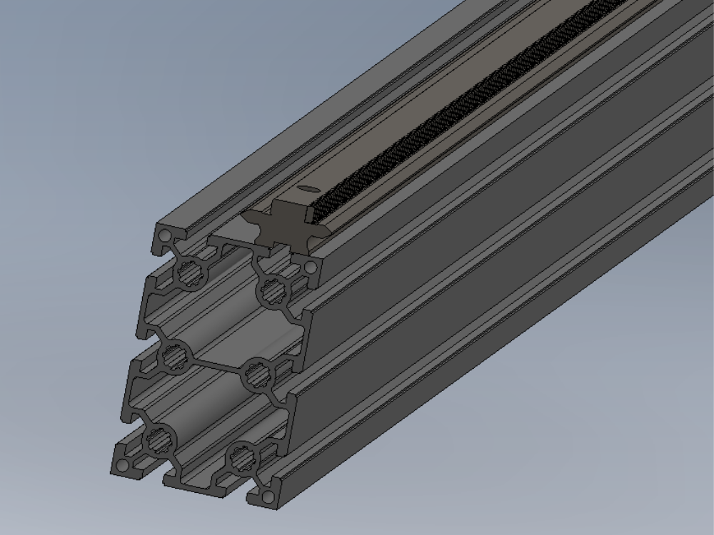
Étape 4 - Position Hepco rail
Orientation
Measurement from end of frame
Correct joining procedure for hepco. V blocks tooth pitching
Q/c when hepco assembled and sat on jigs
Étape 5 - Assemble carriage plate and fit to hepco rail
Correct orientation of journals in relation to rack
Correct setting of journals a multiple points on rack (dokit required for journal setting)
Fit journal wipers
Étape 6 - Checking Levels and adjusting
Quality check of hepco beam on set up jigs
Use carriage plate to check Y axis and X axis levels
Adjustment of axis if not correct
Étape 7 - Laser checks on straightness
Use laser to check straightness of hepco beam on the Y and Z axis
Étape 8 - Mounting brackets
Fitment of mounting brackets to secure hepco beam to frame
Correct fasteners
Q/C check
Dowels?
Étape 9 - Remove set up jigs
Removal of setup jigs
Quality check once jigs removed
Draft
 Français
 English
 Deutsch
 Español
 Italiano
 Português