This dokit details the method of disassembly and list of parts that can be salvaged from a faulty R0000164 spindle assembly
Sommaire
- 1 Introduction
- 2 Étape 1 - Remove drive pulley
- 3 Étape 2 - Remove Grubscrew and extract internal assembly
- 4 Étape 3 - remove quill coupling
- 5 Étape 4 - Remove m6 stud from tooling spindle
- 6 Étape 5 - Remove components from tooling shaft
- 7 Étape 6 - Parts Required to be reused
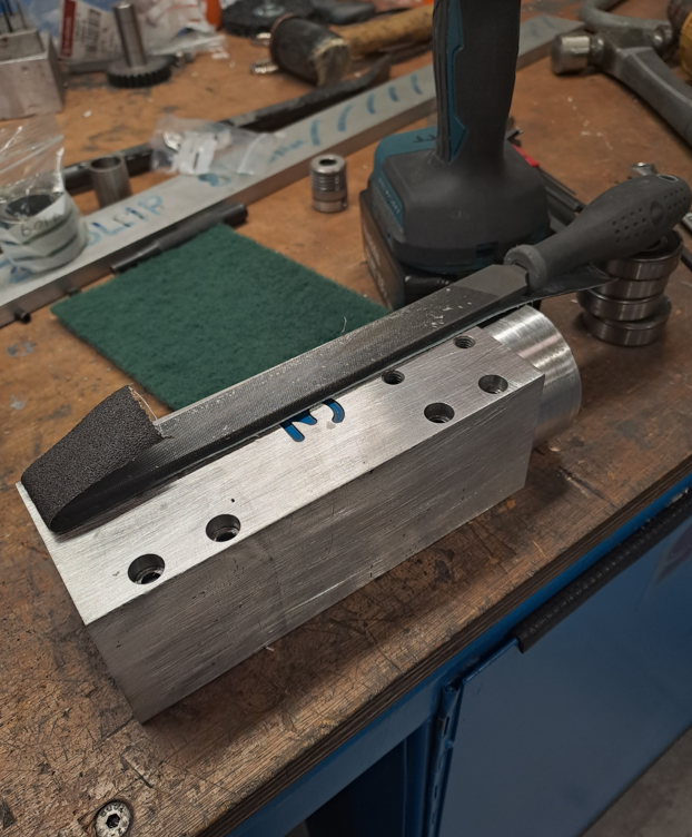
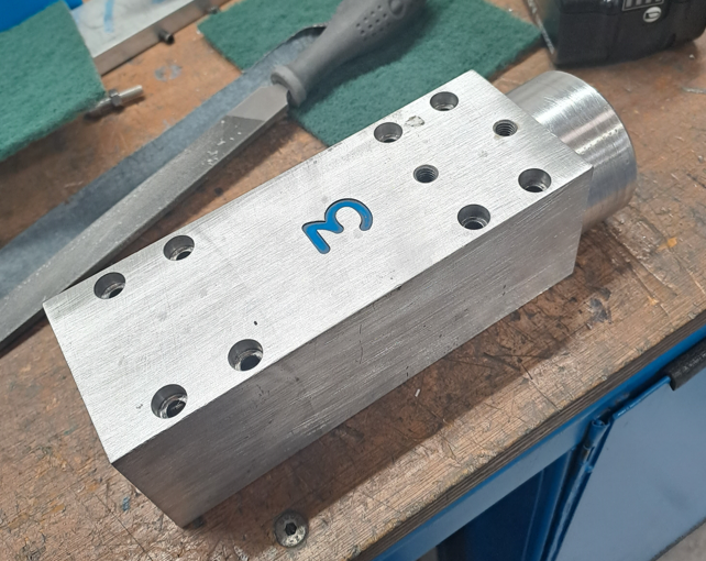
- 8 Étape 7 - Refurbishing D0006018
- 9 Commentaires
Introduction
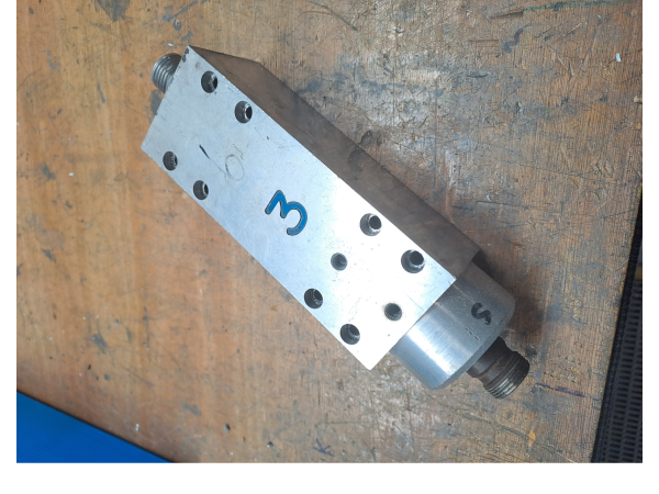
Obsoletion of main pcb tooling holder shaft has created inability to supply replacement spindle units that have failed on site. This procedure will extract required parts from failed units to provide a supply of parts required to create exchange units for R0000164 spindles
Étape 2 - Remove Grubscrew and extract internal assembly
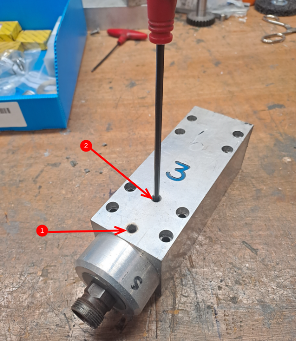
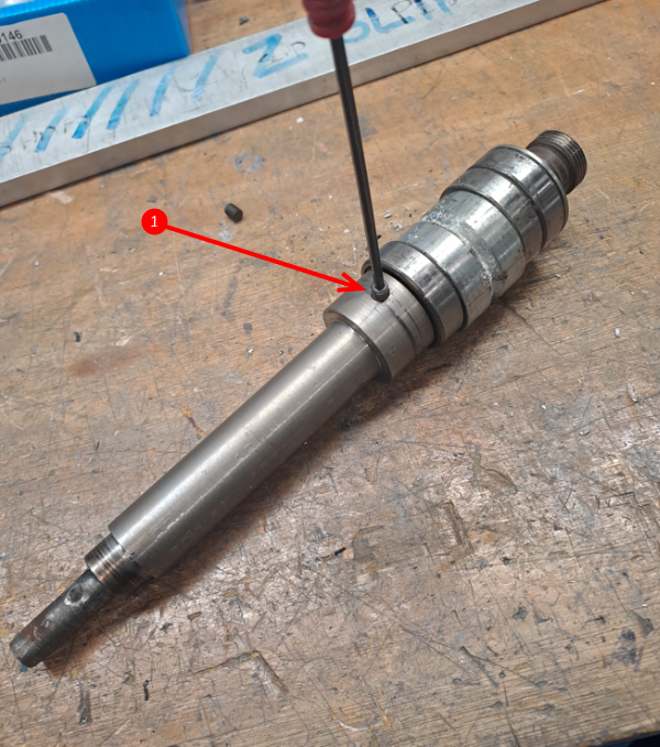
- Remove locating grubscrew
- Remove blanking grubscrew
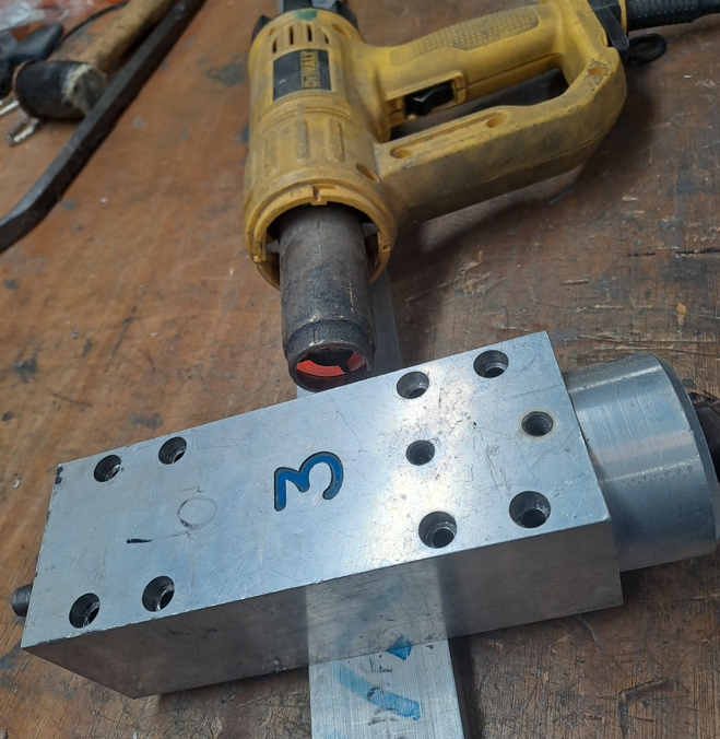
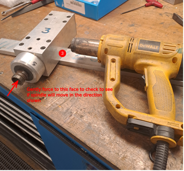
- Apply heat to spindle housing to swell bores
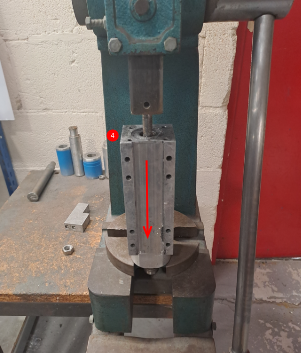
4. Use tool press to push internals out of housing in direction shown
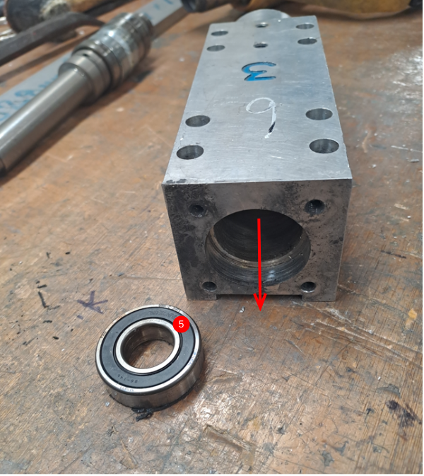
5. Use a drift to remove remaining bearing from housing
Étape 3 - remove quill coupling
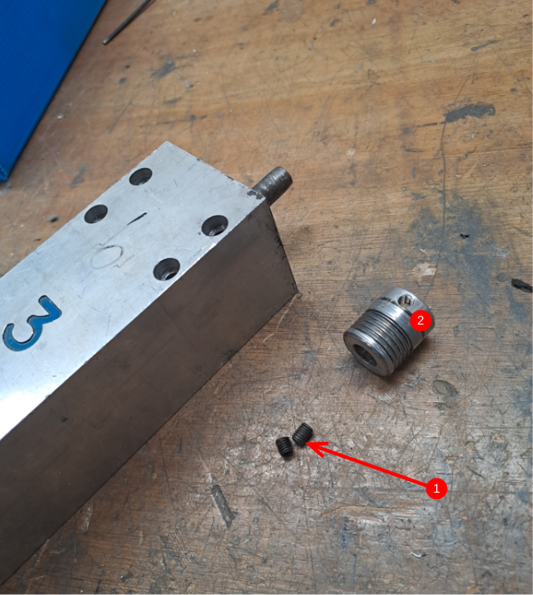
- Remove 2 off M6 grubscrews from Quill
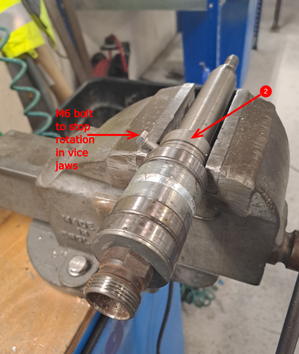
- Apply heat with heat gun to area indicated 2 to melt adhesive holding the quill on to the tooling spindle
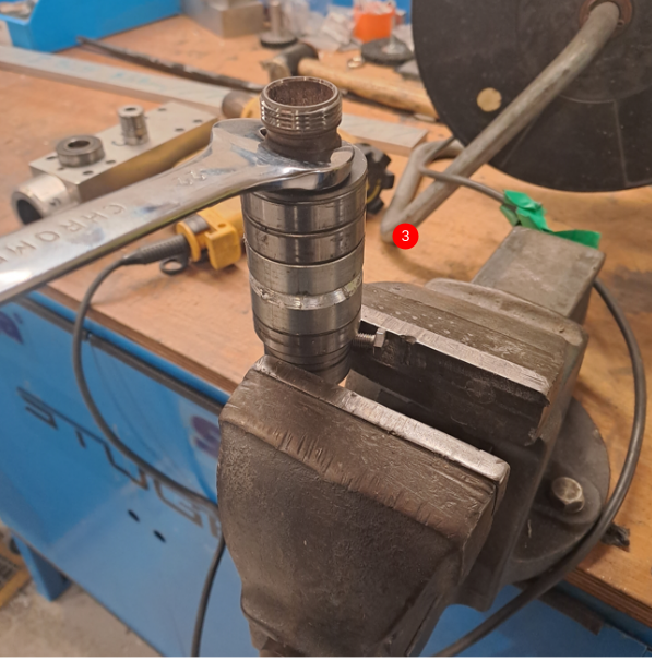
3. Change spindle to a vertical position and use a 22mm spanner to undo the quill housing from the probe
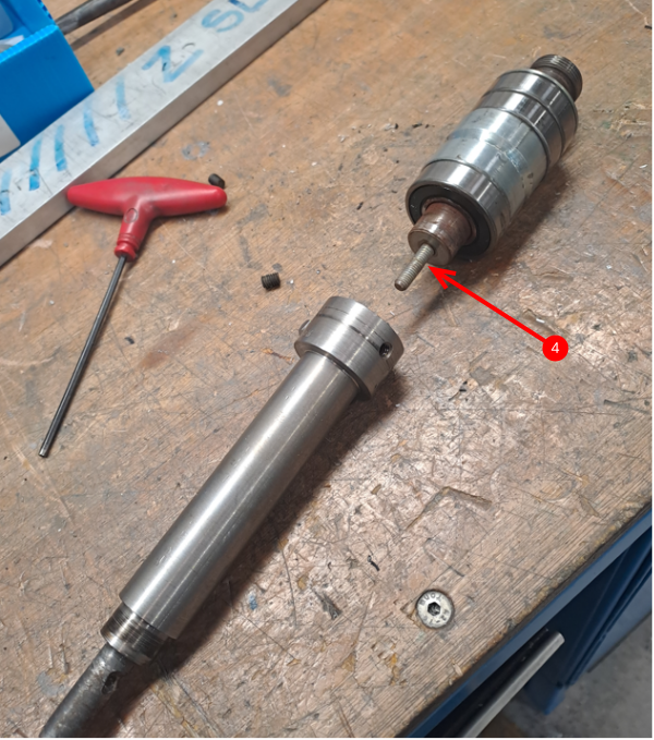
4. The two parts shown separated. M6 studding visible is the mechanical connection between the two parts.
Étape 4 - Remove m6 stud from tooling spindle
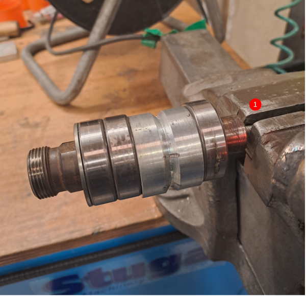
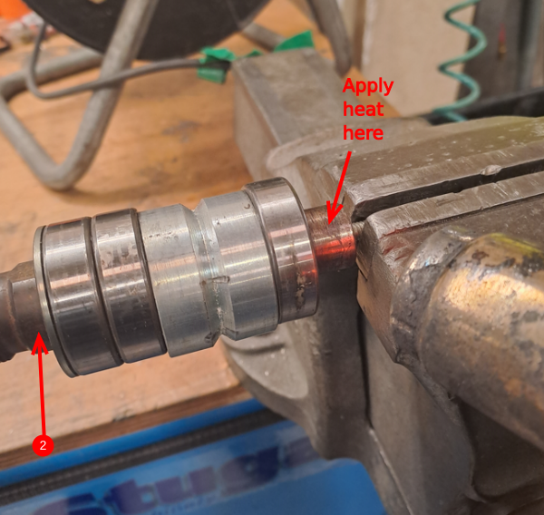
- Clamp M6 studding in vice to hold in position
2. Apply heat with a heat gun in the area indicated to melt and break the stud lock that will have been applied. Use a 22mm spanner on the flats indicated to rotate the tooling shaft off the m6 studding
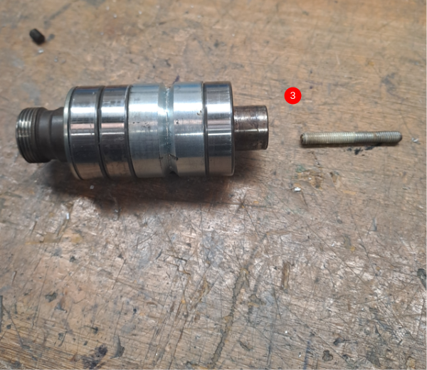
3 Studding and tooling shaft shown separated
Étape 5 - Remove components from tooling shaft
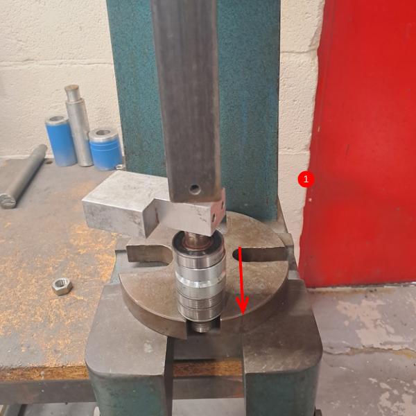
1. Use tool press to push tooling shaft through bearings
2. If tooling press is unable to split bearings from shaft , impact must be used.
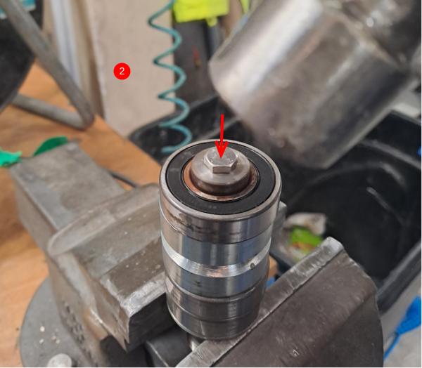
To do this, add a m6 set bolt to the hole shown. This will act as protection for the tooling shaft from the impact
Hold the assembly in the vice as shown and impact the set bolt with a hammer in the direction shown to break the seating of the bearings on the shaft
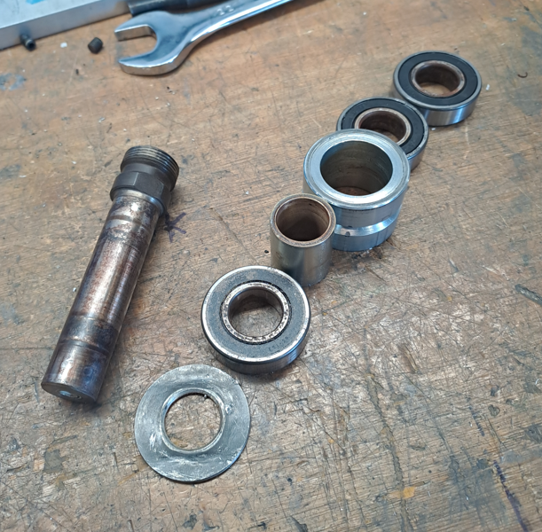
3. components shown removed from the tooling shaft
Étape 6 - Parts Required to be reused
IF requested, the following parts will require refurbishing and reusing for a new spindle rebuild.
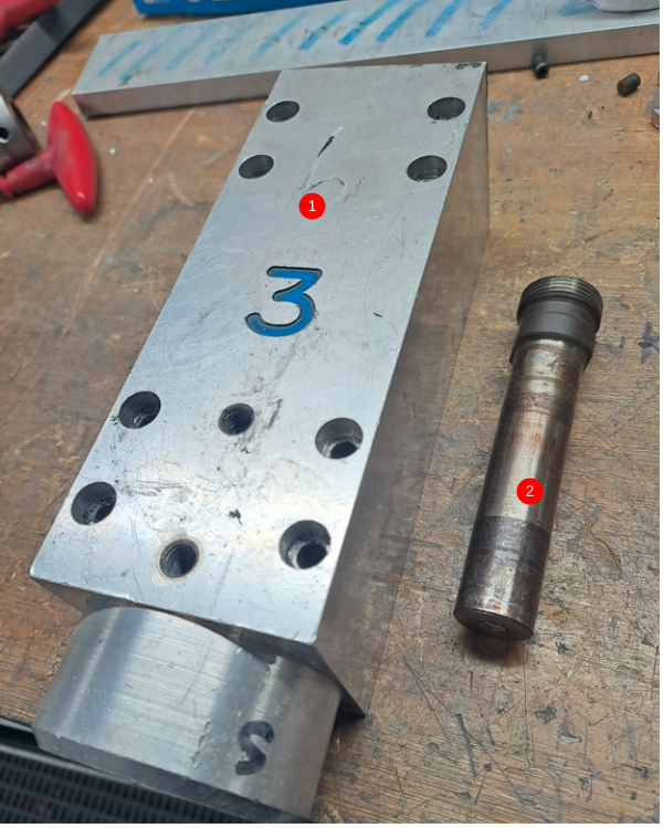
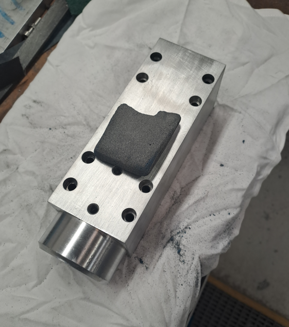
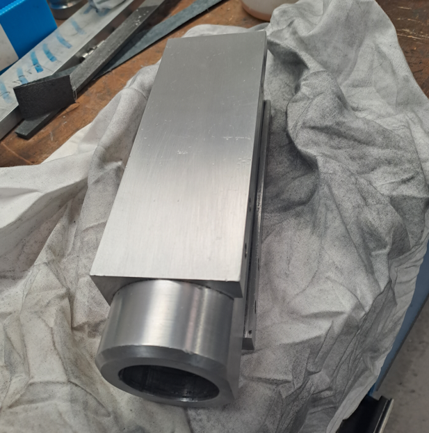
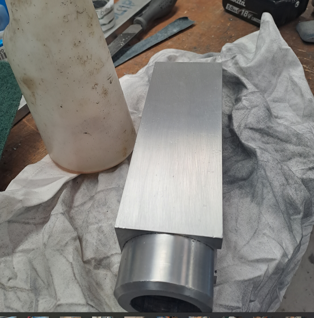
- Spindle Housing D0006018
- Tooling spindle and Nut H0006011
Draft
 Français
 English
 Deutsch
 Español
 Italiano
 Português