Upgrade to enhance mechanical connection between drive spigot and SR gearbox. Upgrade to allow removal of SR gearbox efficiently

Difficulté
Difficile
Durée
8 heure(s)
Sommaire
- 1 Introduction
- 2 Étape 1 - Disconnect Saw cut cylinder connections
- 3 Étape 2 - Disconnect Saw head guards, chutes and ancillary parts
- 4 Étape 3 - Relocate Motor assembly
- 5 Étape 4 - Main saw head disconnections
- 6 Étape 5 - Remove saw head from turntable
- 7 Étape 6 - Turntable plate removal
- 8 Étape 7 - Lower turntable disconnections
- 9 Étape 8 - Lower turntable disconnections
- 10 Étape 9 - Spigot pin removal
- 11 Étape 10 - Gearbox dowel pin fitting
- 12 Étape 11 - Refitting bearing housing
- 13 Étape 12 - Fitment of alignment parts
- 14 Étape 13 - Fit Sr axis gearbox
- 15 Étape 14 - Greasing
- 16 Étape 15 - Fit turntable plate
- 17 Étape 16 -
- 18 Étape 17 - Fit Sr axis gearbox
- 19 Étape 18 - Greasing
- 20 Étape 19 - Fit turntable plate
- 21 Étape 20 - Rebuild
- 22 Commentaires
Introduction
This upgrade utilises upgraded parts to ensure a mechanical fix is maintained between the SR axis gearbox and main drive pin , whilst also giving the ability once upgraded for the gearbox to be removed with minimal mechanical time.
three main parts will be replaced in this upgrade, obsoleting the removed parts
Main components of upgrade
D00004019E Turntable Mk5
D0004033E Alignment disc Mk5
D0004147E Turntable shaft Mk5Étape 1 - Disconnect Saw cut cylinder connections
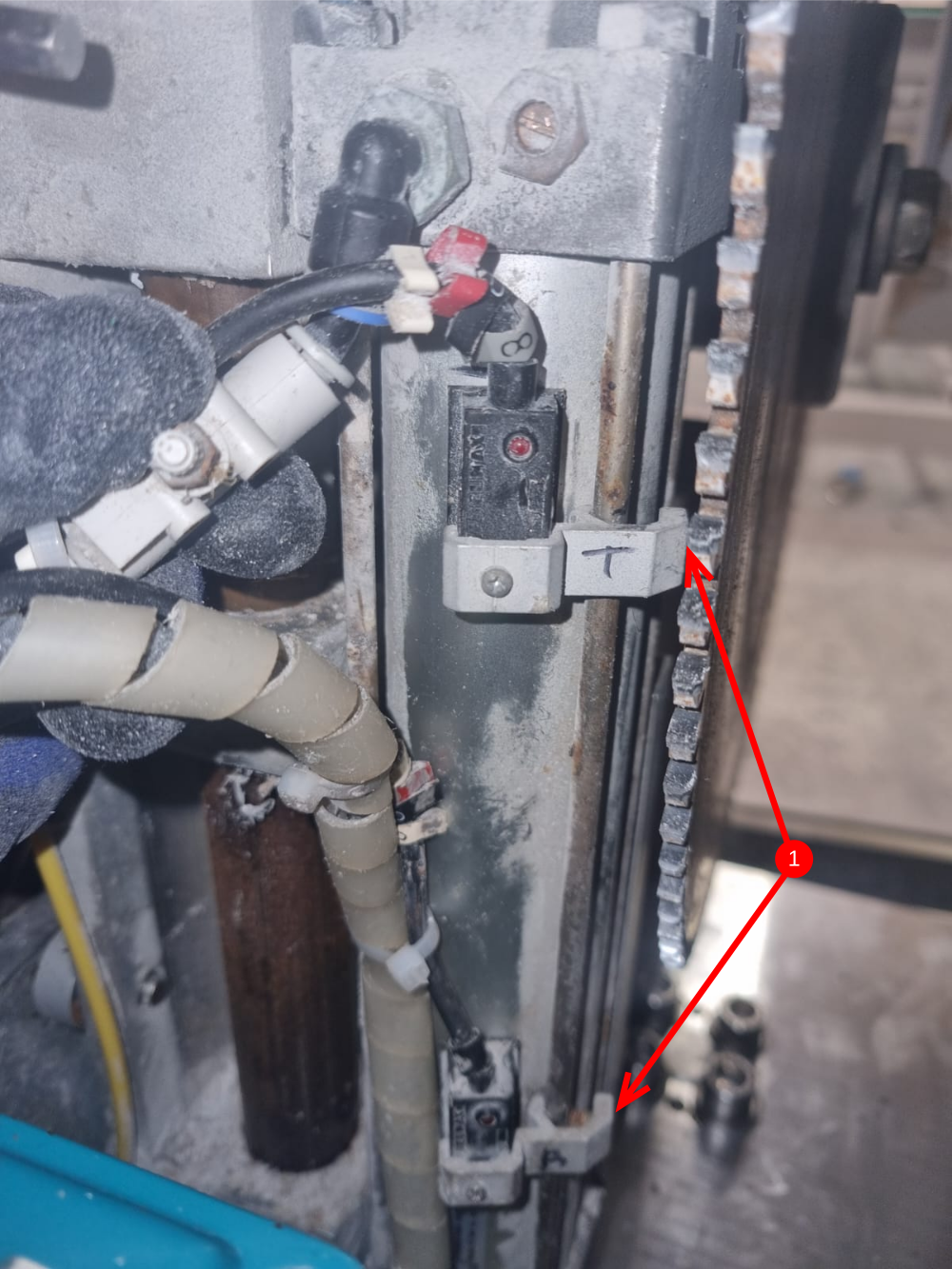
1 Disconnect saw cut reed switches. Mark position of bracket before removal to aid re-assembly
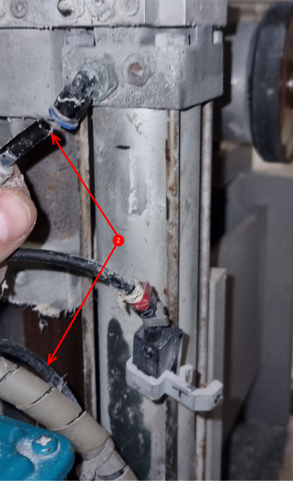
2 Disconnect saw cut cylinder air pipes
3 Disconnect saw cut cylinder piston rod as shown
Étape 2 - Disconnect Saw head guards, chutes and ancillary parts
1 Remove saw blade
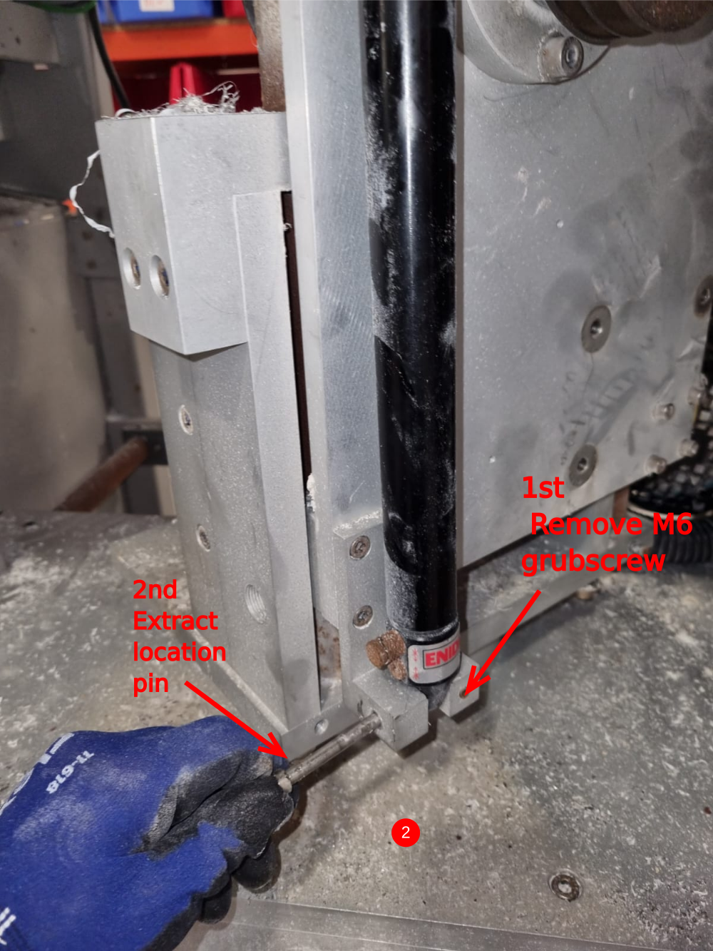
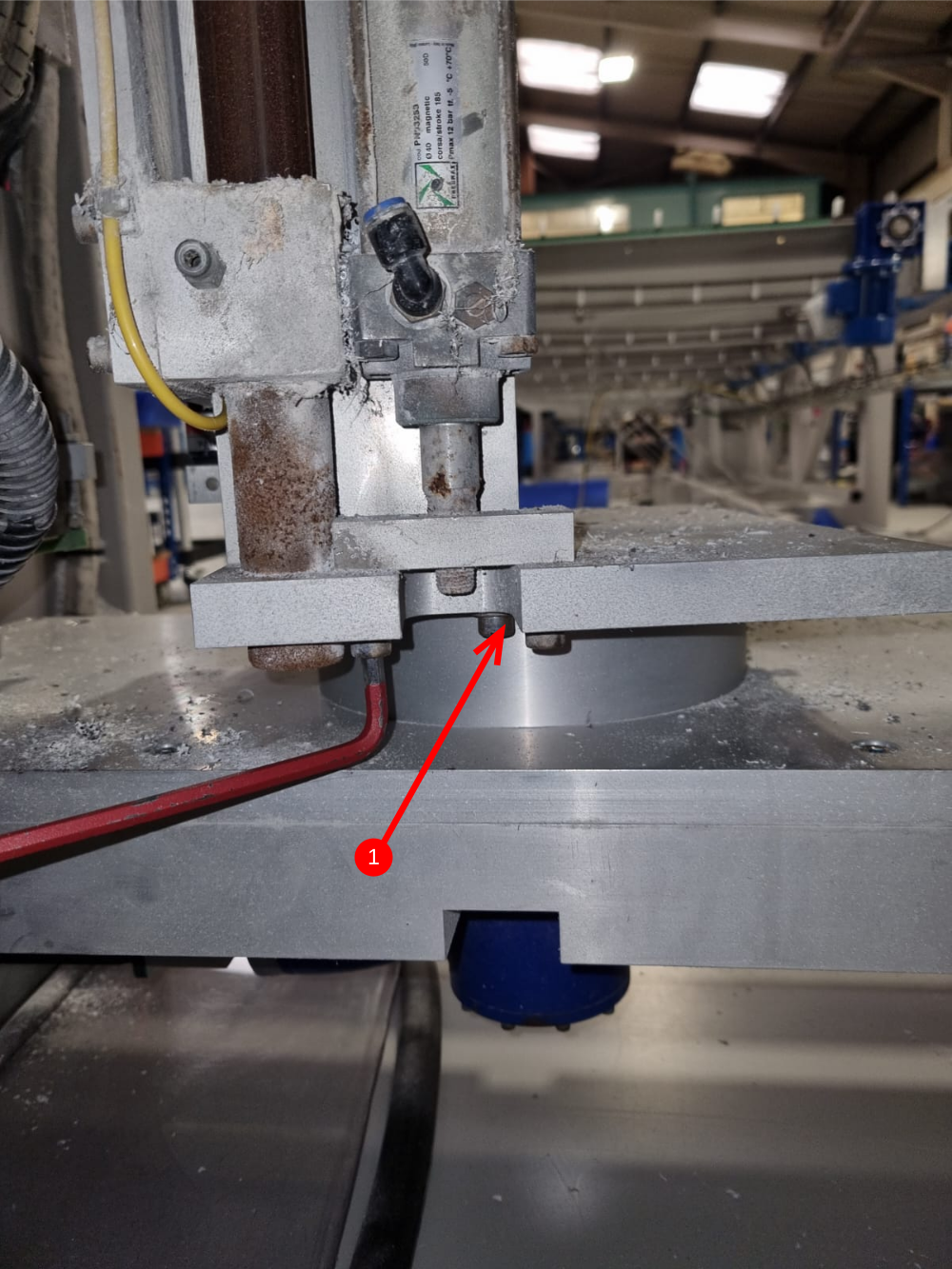
2 Remove saw cut damper buy removing 2 off m6 grubscrews and then retracting 2 off location pins
3 Remove top semi circular guard with slit strips attached, remove swarf chute and supporting T bracket
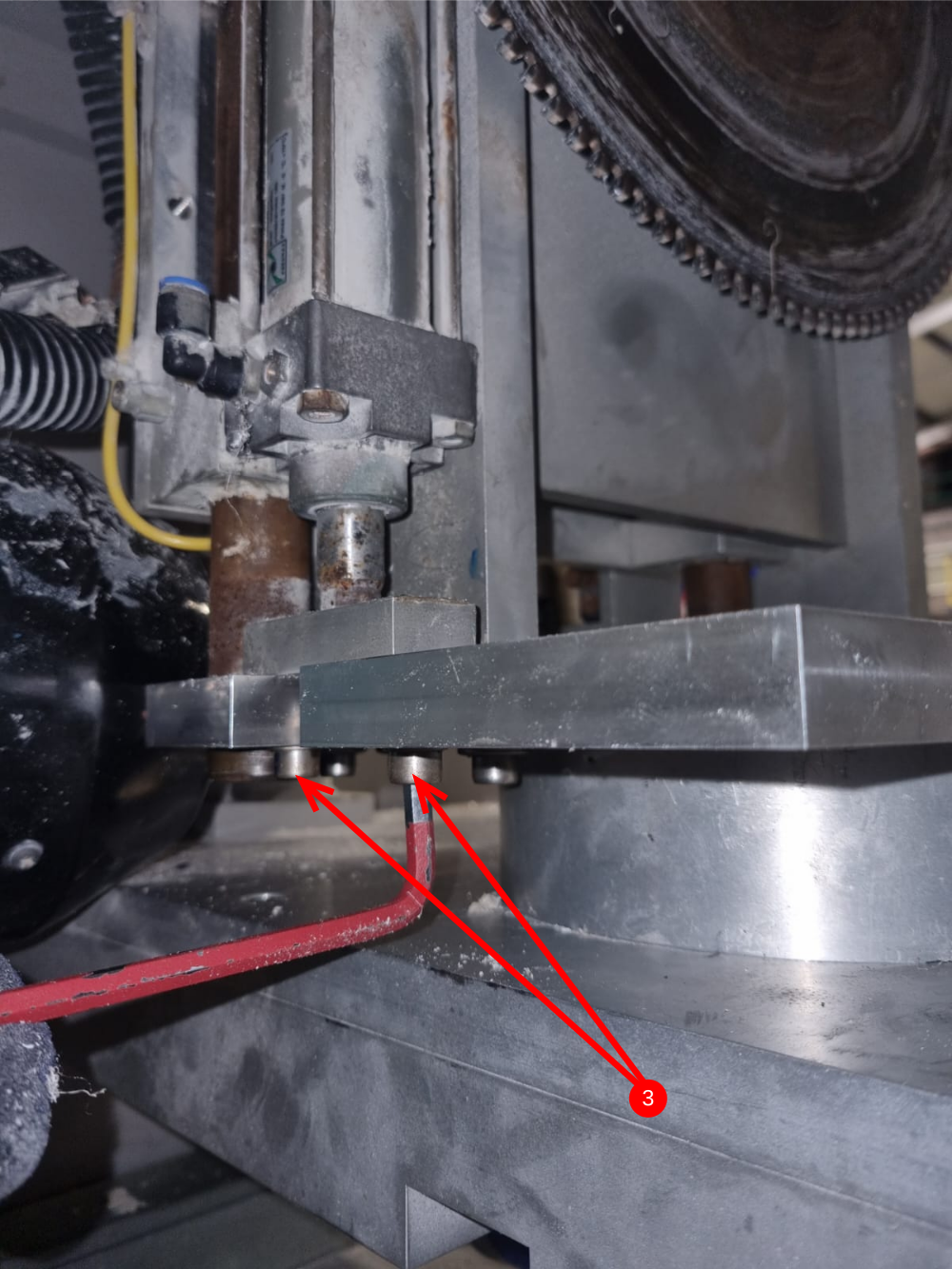
4 Remove top brace bar located on top of saw cut shafts as shown
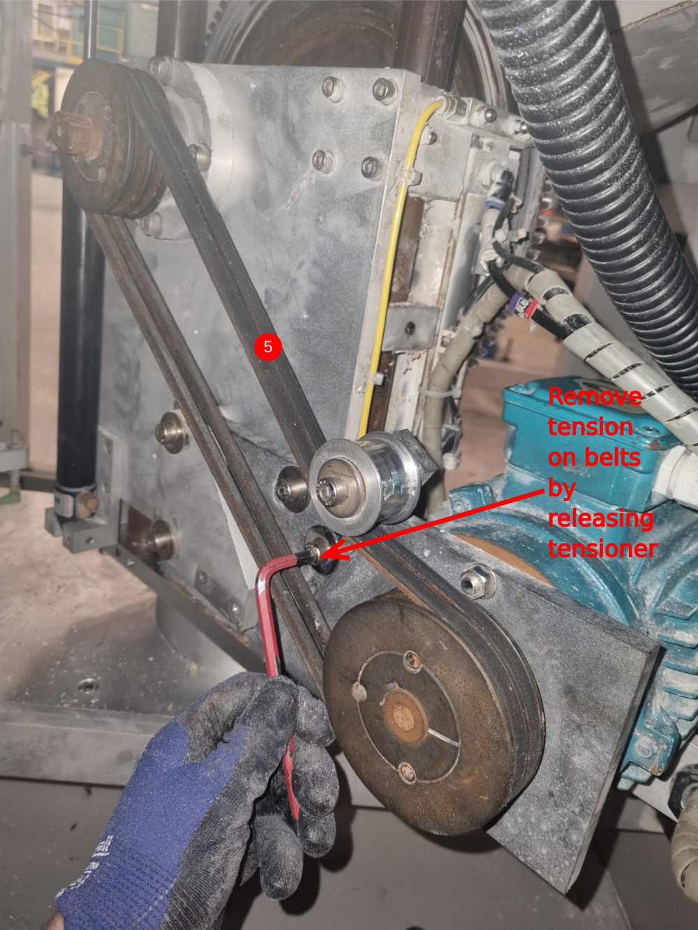
5 Remove saw motor belts

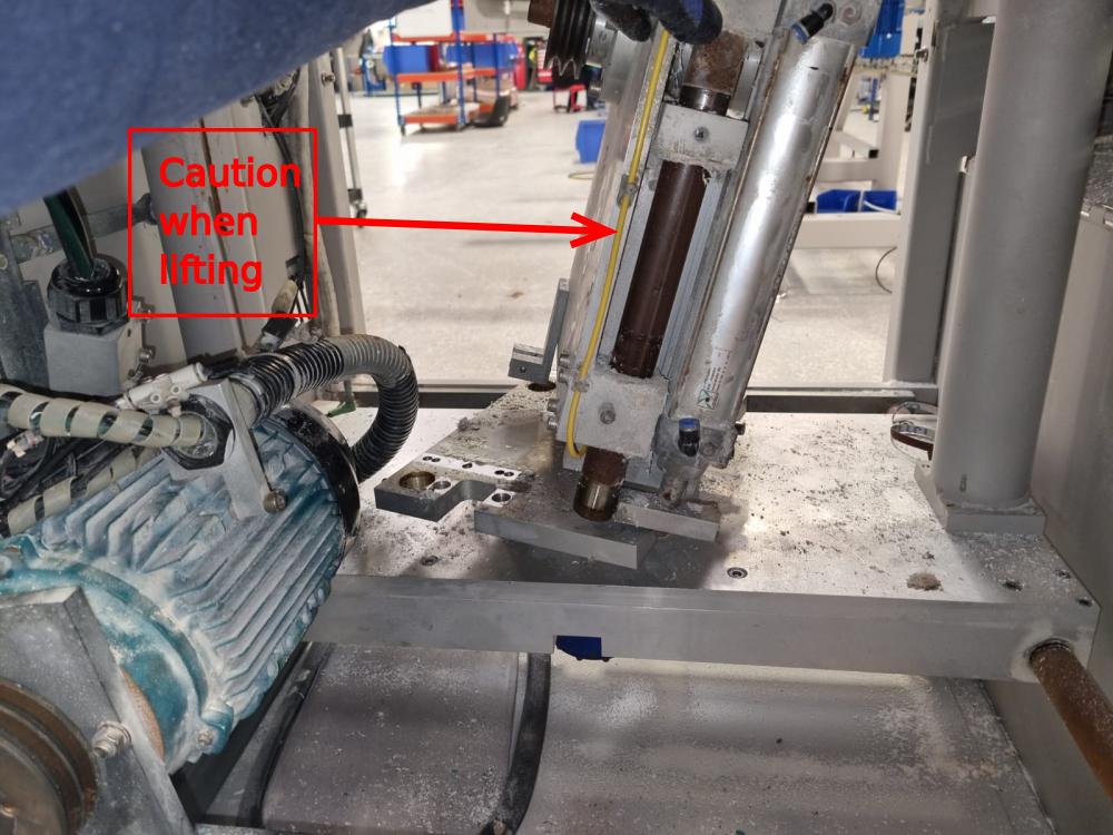
Étape 3 - Relocate Motor assembly
Saw motor with mounting plate will now need removing from the saw head assembly
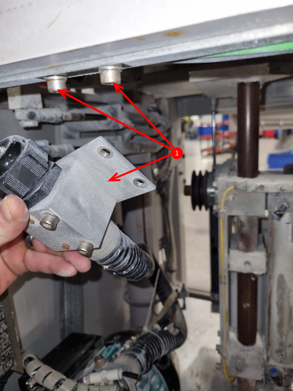
1 Disconnect saw anaconda as shown
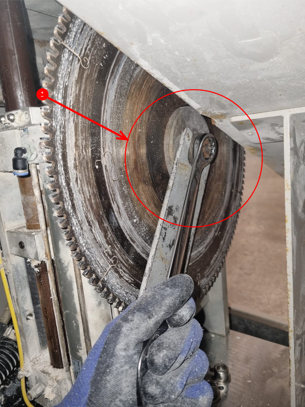
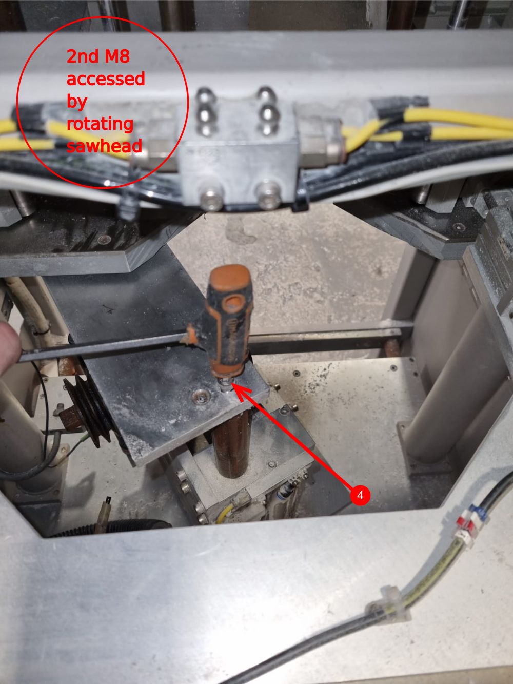
2 Whilst supporting the saw motor, remove the 3 off m8 cap heads and swing the saw motor assembly and attach the frame , and secure for safe working

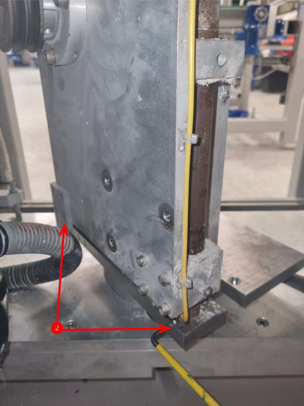
Étape 4 - Main saw head disconnections
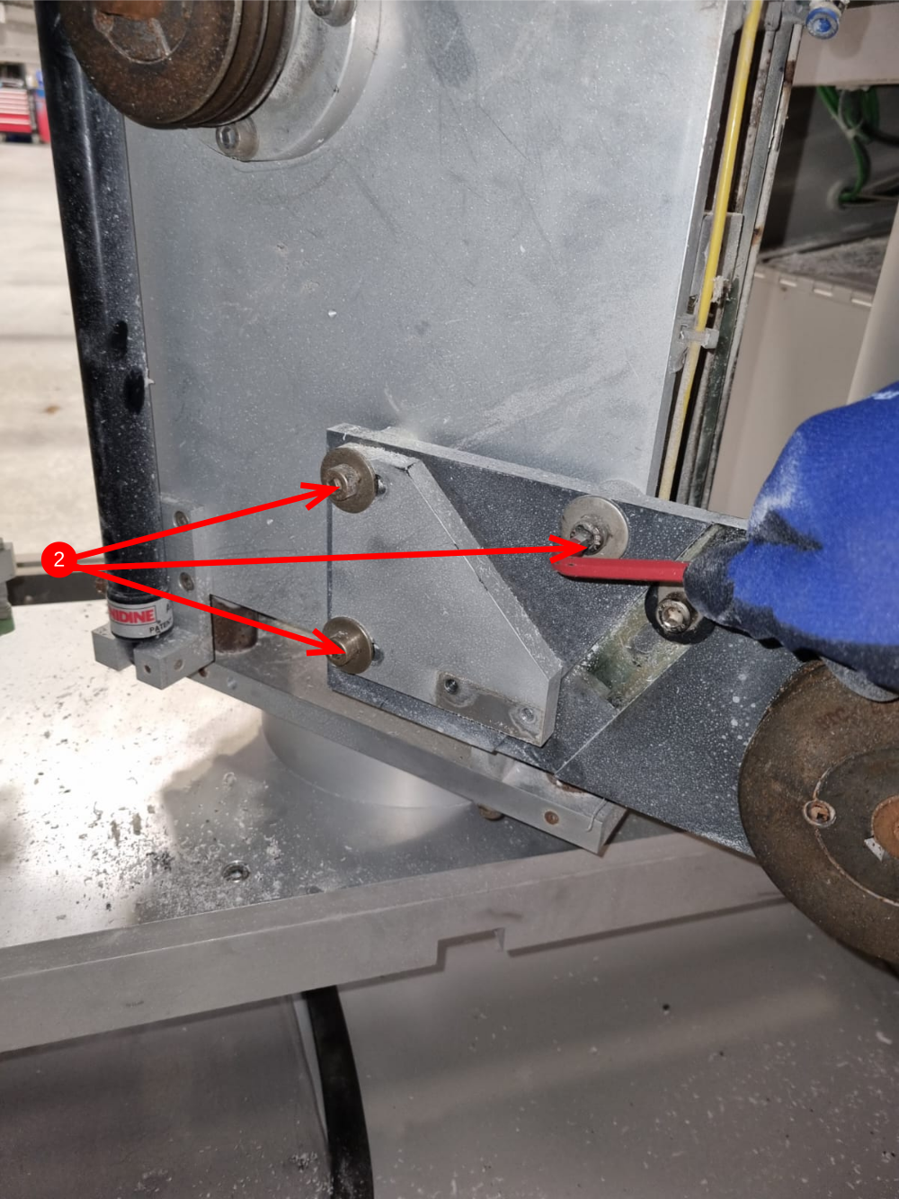
1 Remove 6 of M8 caps heads from underneath main saw mount plate (3 per side )
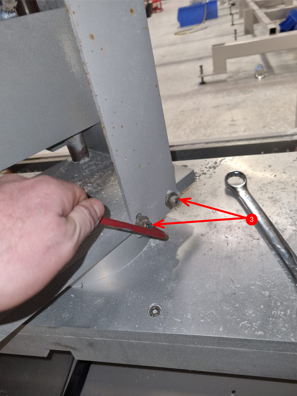
2 Remove 2 off m8 grubscrews locating saw cut shafts to turntable base
3 The head assembly can then be removed by levering the base of the two saw cuts shafts , pushing them upwards to release the complete head assembly from the turntable base
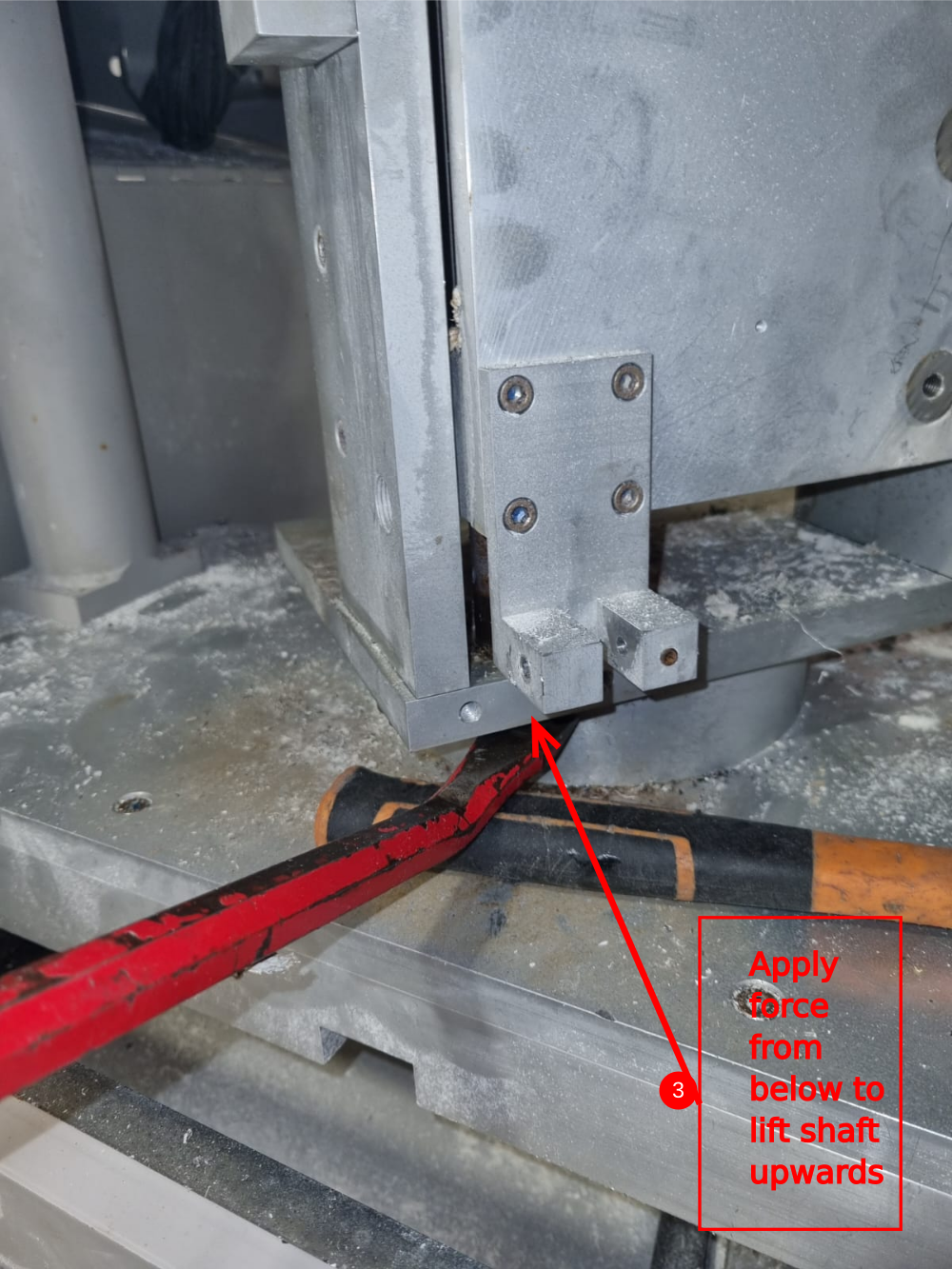
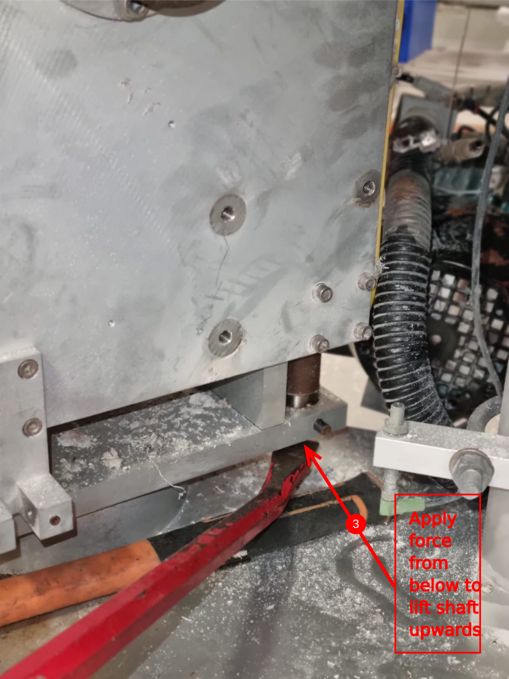
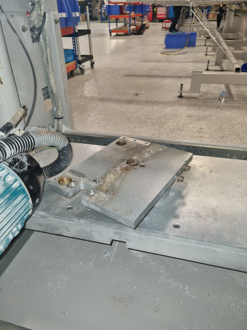
Étape 5 - Remove saw head from turntable
Once the assembly is disconnected it can be removed and allow access to the turntable base as shown

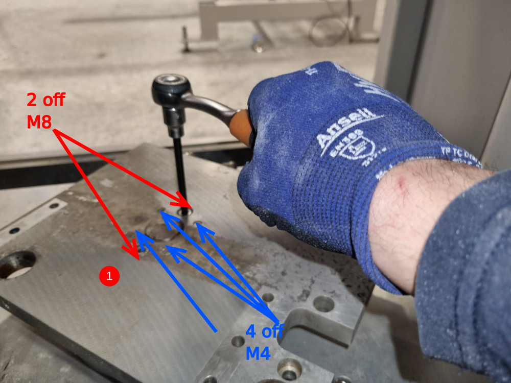
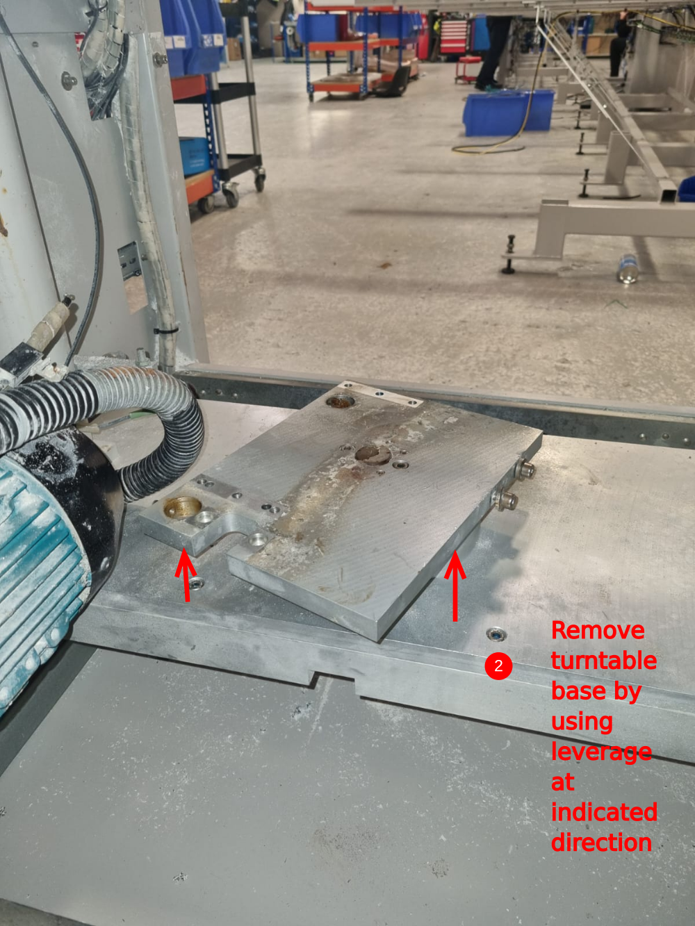
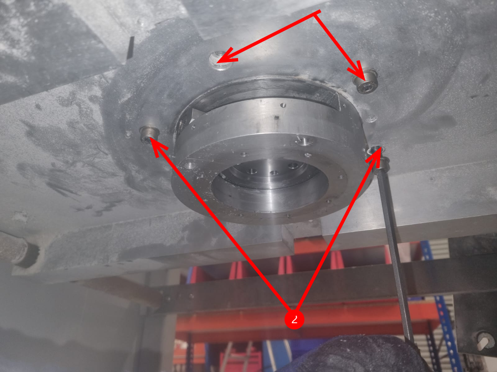
Étape 6 - Turntable plate removal
1 Remove the m8 caps from the top face off the turntable plate, along with the 4 off m4 caps. The remaining 8mm dowels visible cannot be extracted, but will be released once the turntable plate is removed.
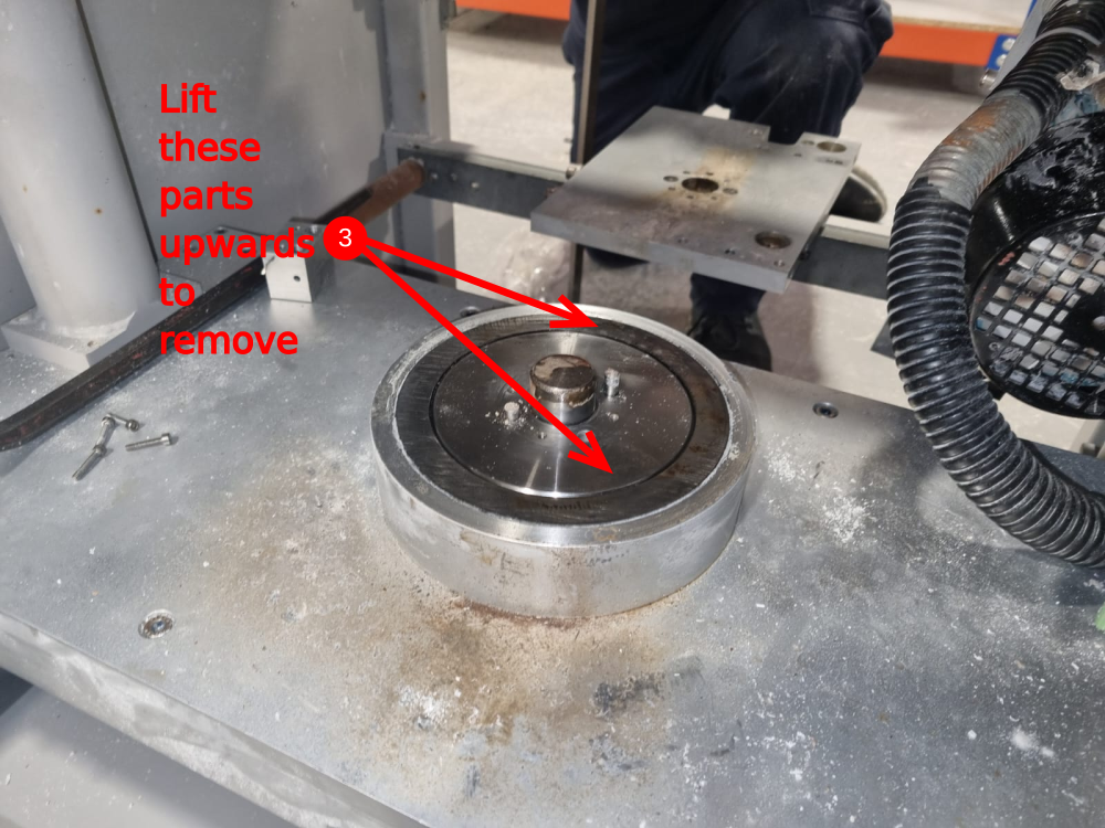
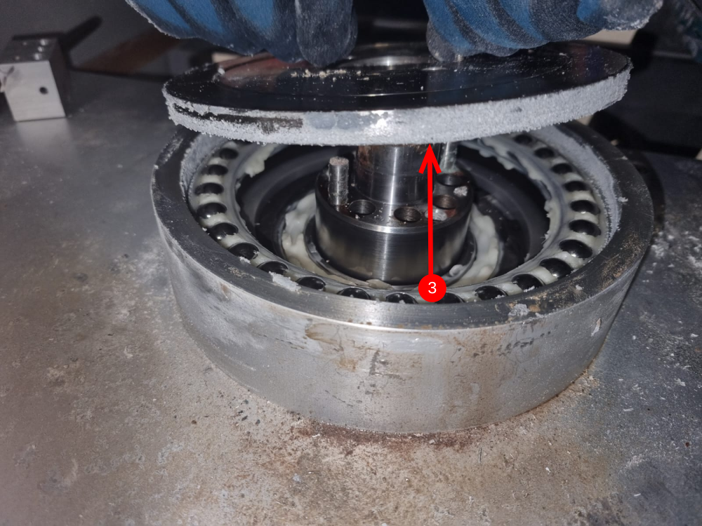
2 To remove the plate , use leverage to force the plate up evenly, to expose the main bearing and alignment disc below
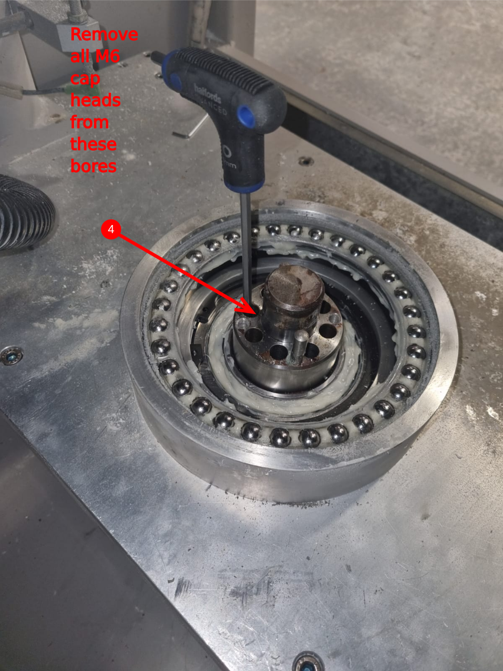
3 Now the top section of the main bearing and alignment disc can be lifted off, exposing the bores to access the gearbox fixings.
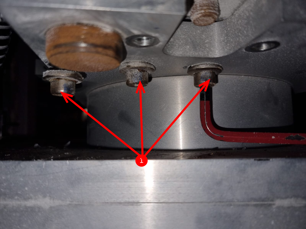
4 Remove the m6 cap head bolts as shown

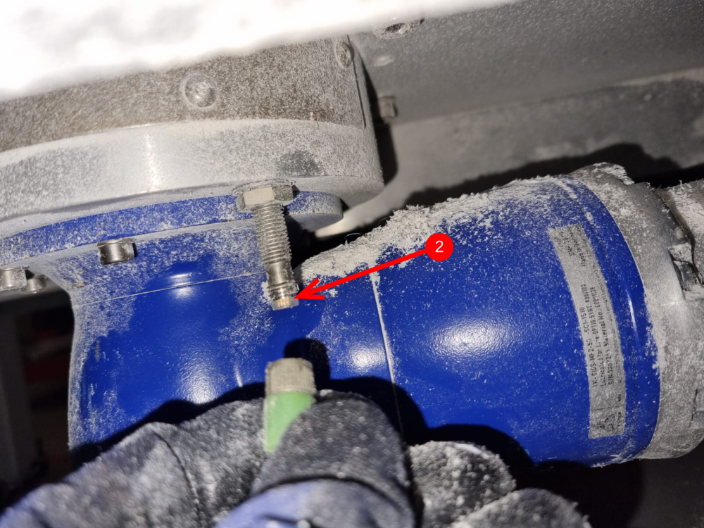
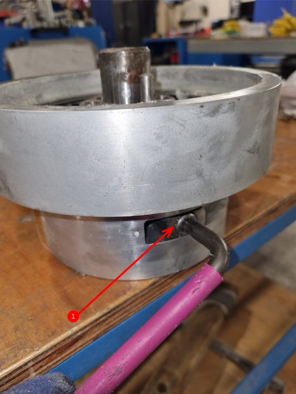
Étape 7 - Lower turntable disconnections
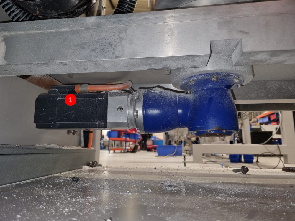
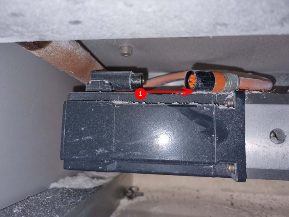
1 Disconnect the servo motor plug
2 Disconnect (if present) the m8 sensor plug
3 Remove m5 fixings around gearbox mounting flange to allow the gearbox and motor to be removed
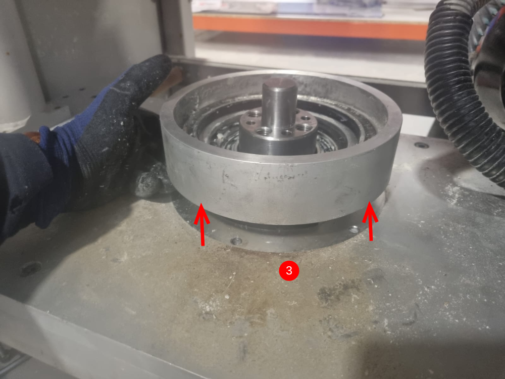
Étape 8 - Lower turntable disconnections
1 Remove stainless inspection cover
2 Remove 6 off m8 cap heads
3 Main turntable housing can now be removed, by lifting upwards through the main bottom plate

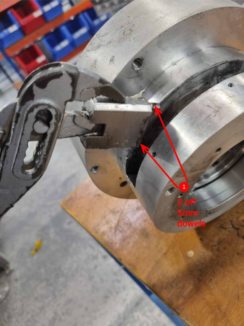
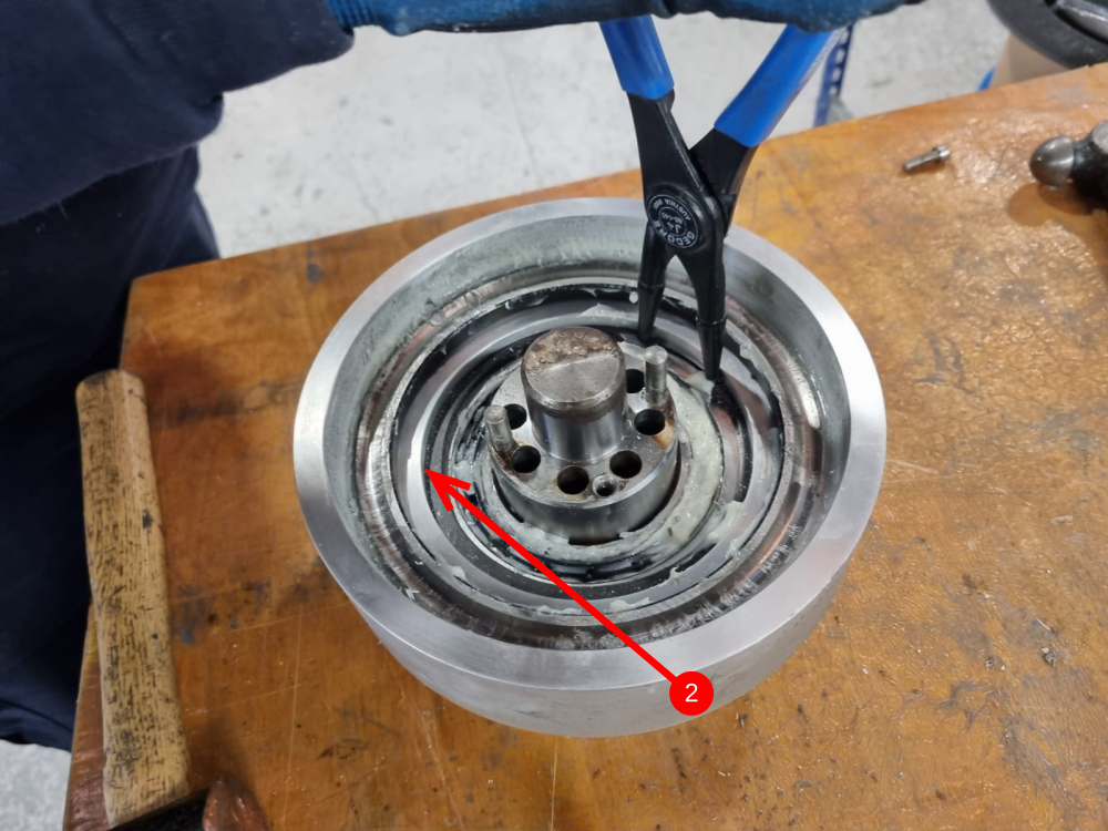
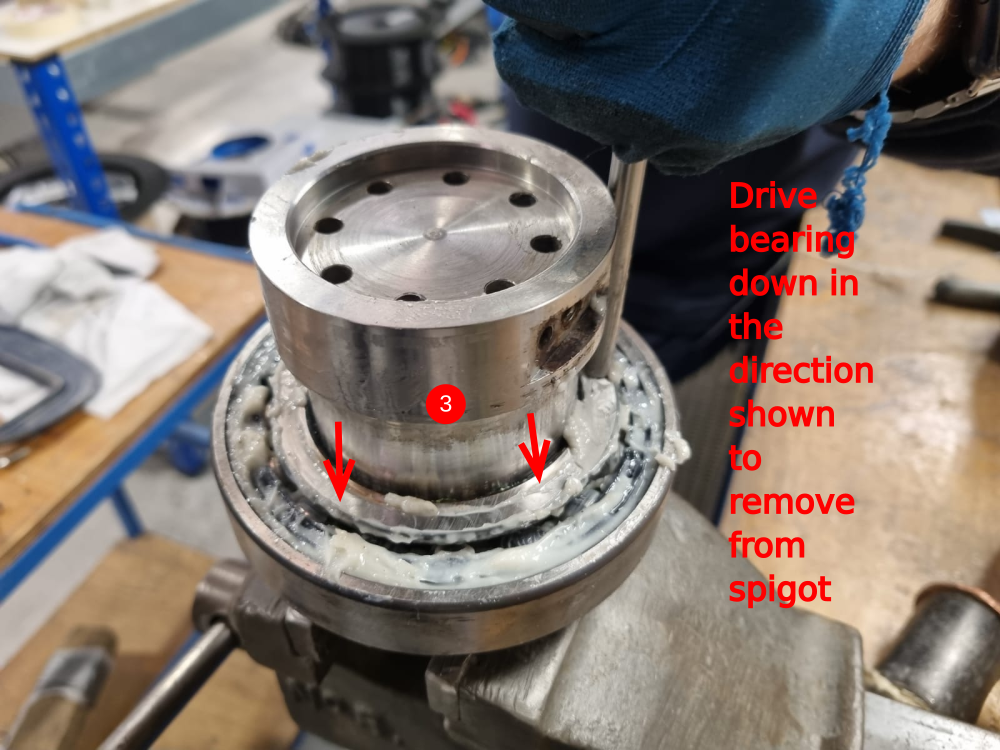
Étape 9 - Spigot pin removal
1 Remove hard stop, attached with 1 off m10 bolt and 2 off 5mm dowels
2 Remove internal circlip that captivates the centre thrust bearing
3 Remove bearing and spigot assembly as one from within the main bearing housing, and then remove bearing from the spigot shaft
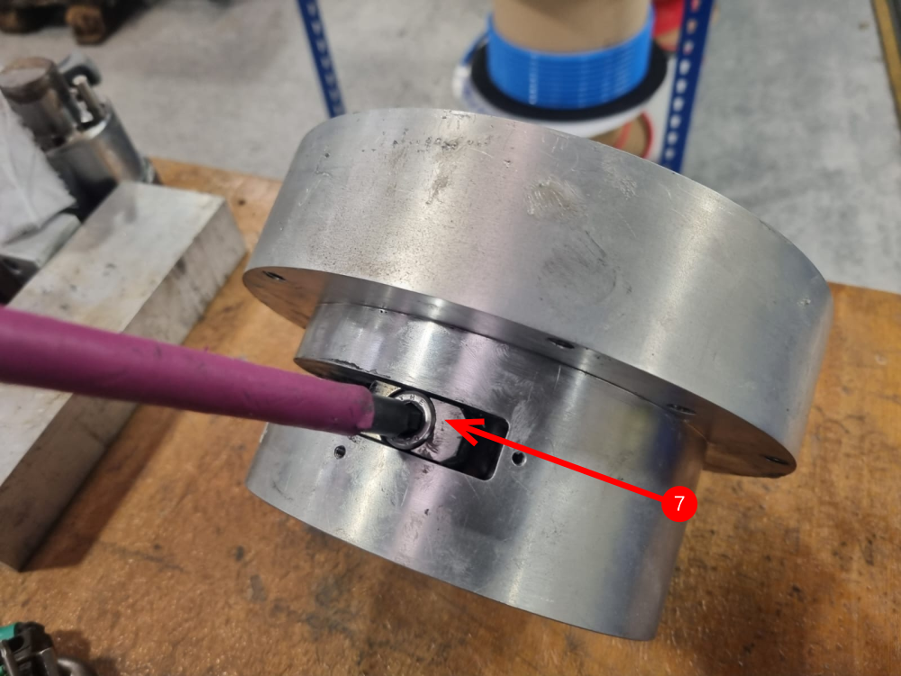
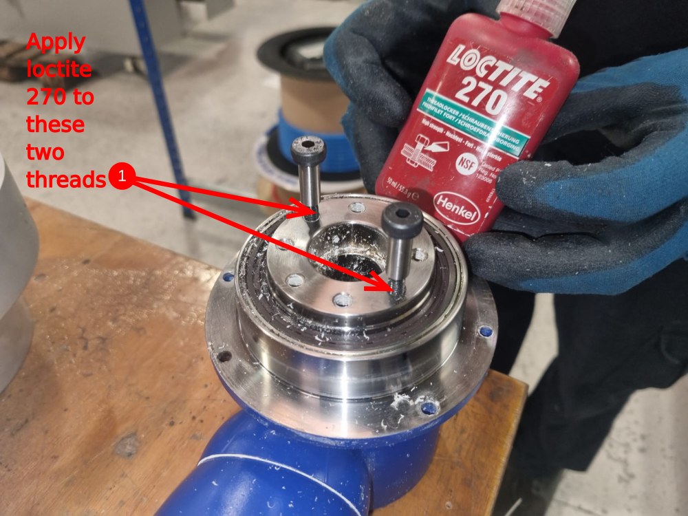
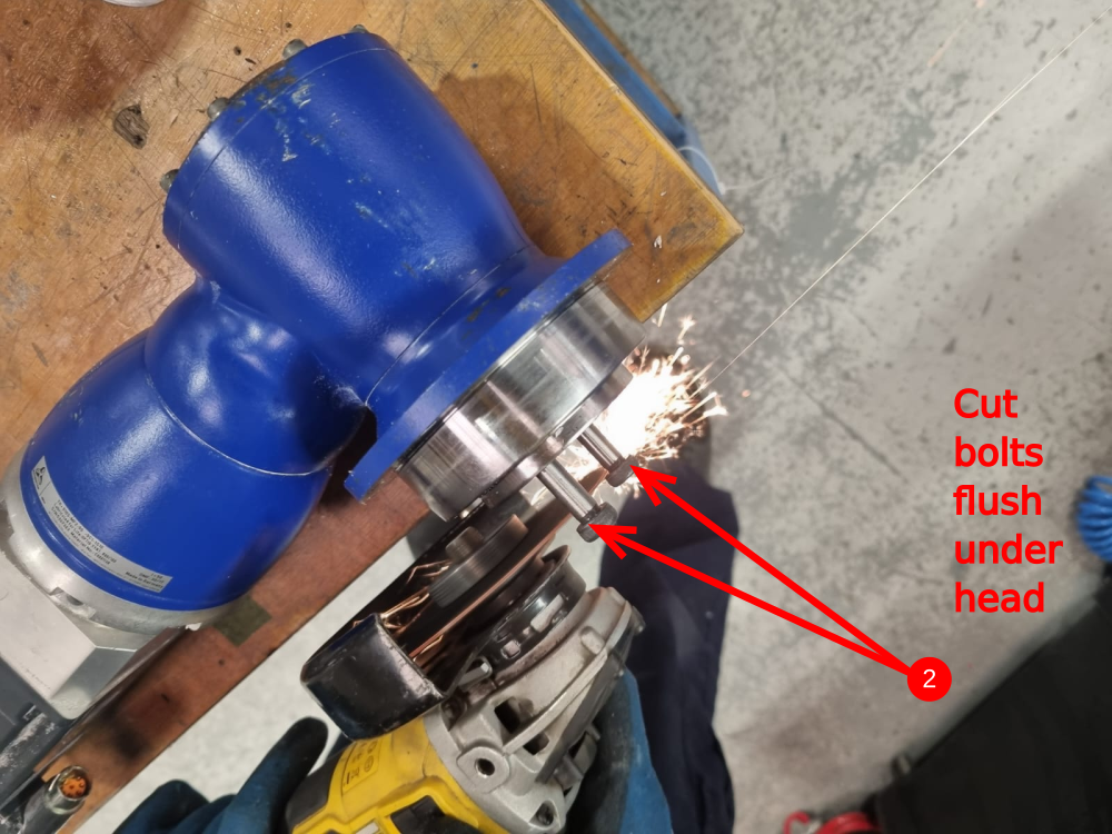
Étape 10 - Gearbox dowel pin fitting
1 Fit 2 off m6 shoulder bolts to opposing m6 holes on gearbox mounting face and glue with loctite 270 permanent adhesive
2 Remove heads of shoulder bolts once tight
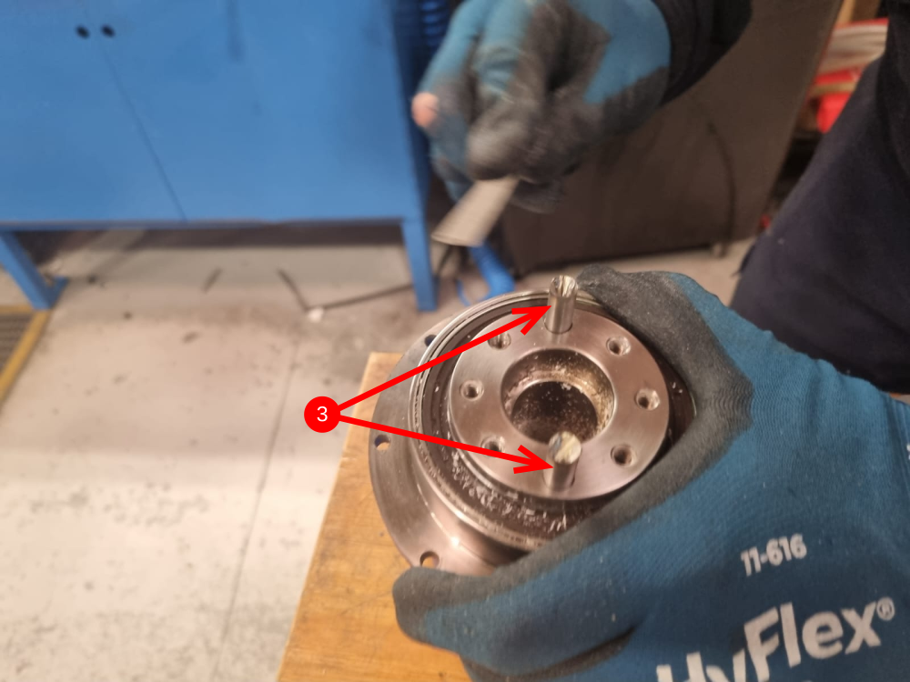
3 Deburr cut dowels
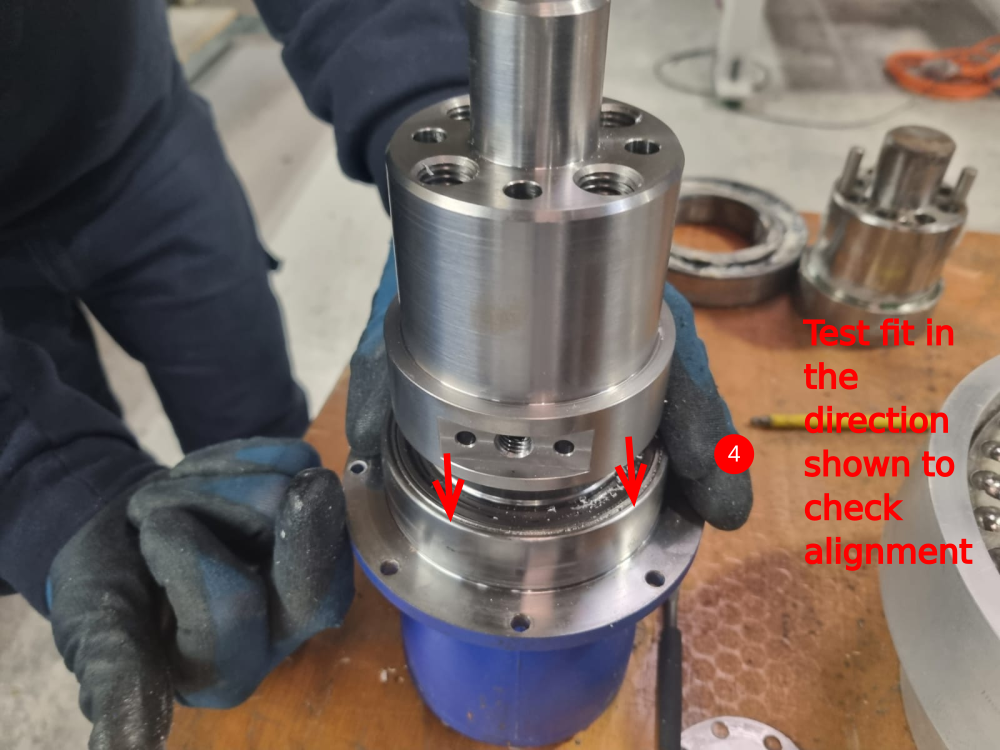
4 Test fit onto new d0004147E spigot shaft
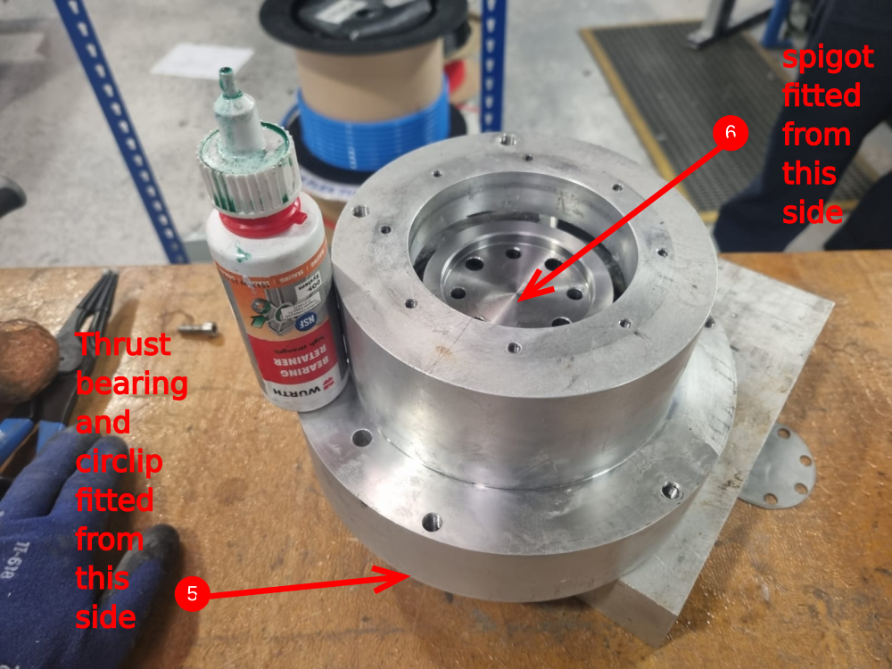
5 Refit thrust bearing to main saw turntable housing and refit circlip
6 Fit spigot shaft back into thrust bearing .
7 Refit hard stop to assembly
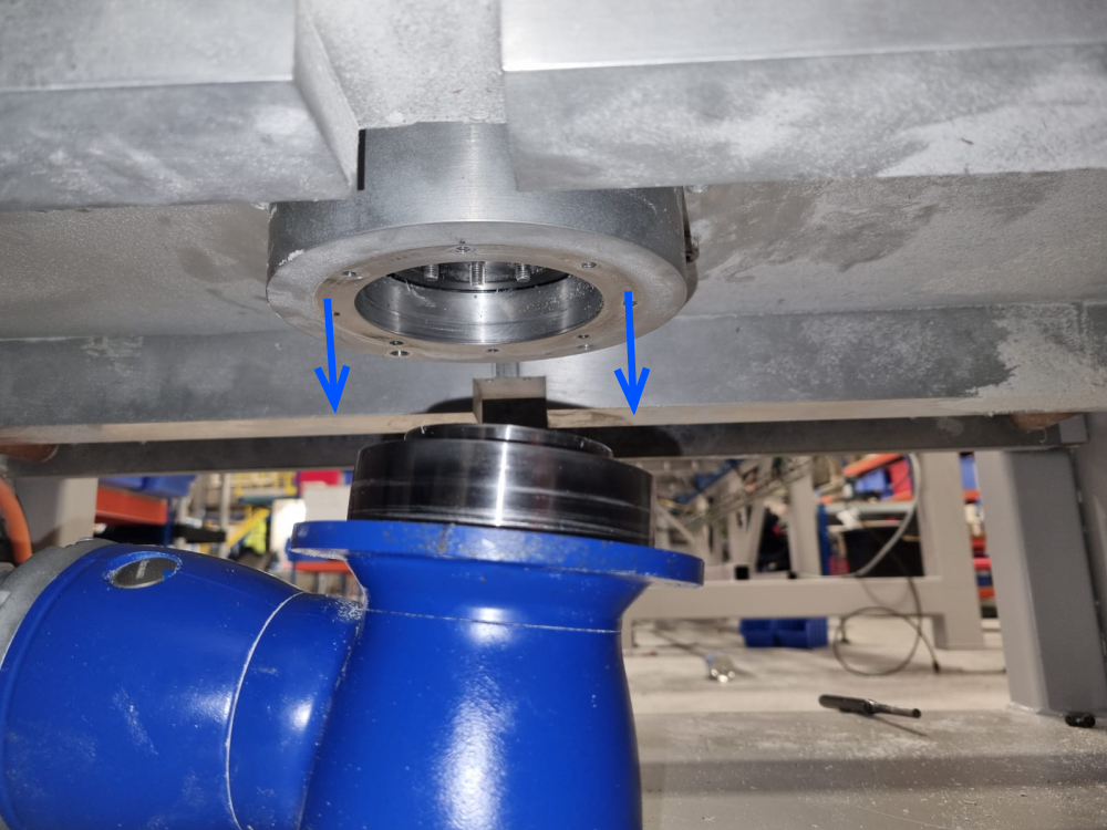
Étape 11 - Refitting bearing housing
Refit bearing housing assembly to main plate

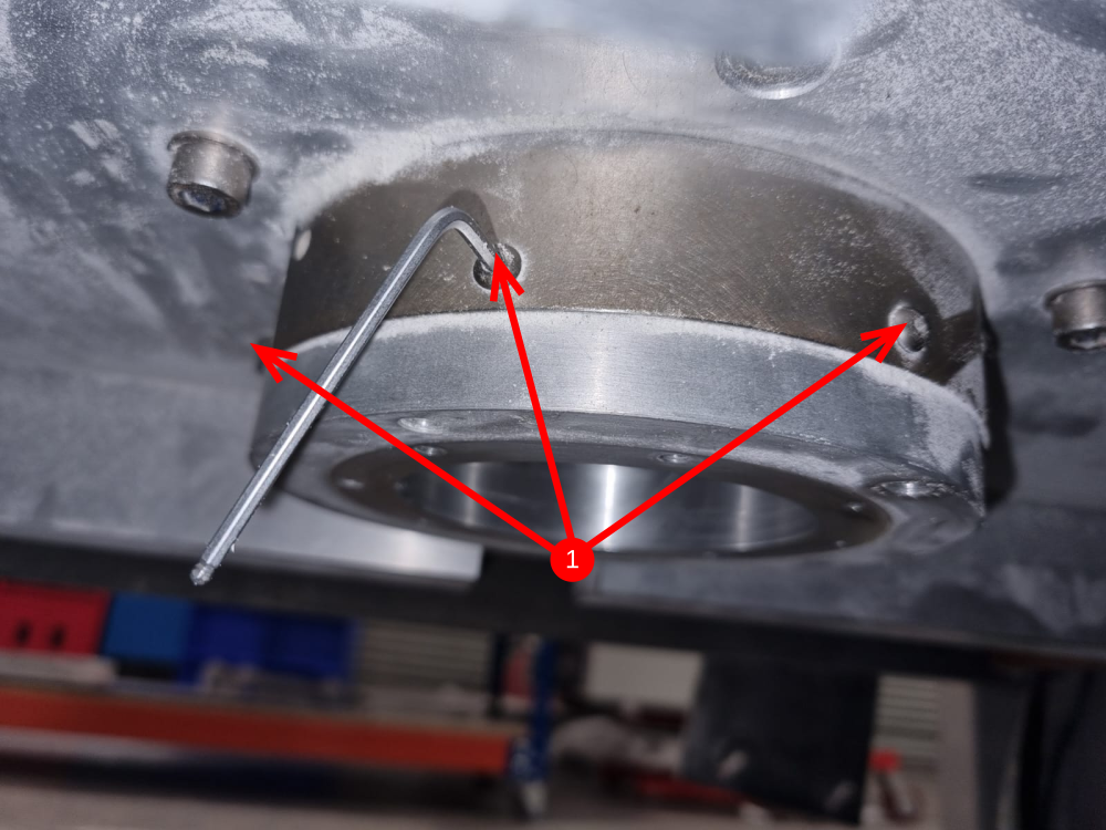
Étape 12 - Fitment of alignment parts
Assemble alignment disc to bearing outer . Hold in place with slightly tensioned M4 caps
Use an 8mm reamer to check holes will accept an 8mm dowel through both parts


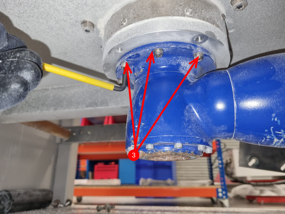
Étape 13 - Fit Sr axis gearbox
Connect the gear box , using the 2 dowels on the gearbox as location, then using 4 off m6 x 20 blackadised unbrako bolts, loctite 243 and M0001176 4 off stainless lock washers to connect the parts together. Torque setting on 15nm should be used to set these m6 bolts
Refit m5 Fixings to lower gearbox flange from underneath turntable


Étape 14 - Greasing
Thoroughly grease both bearings as this is a sealed for life unit. Liberal application of M0000494 grease is required
Étape 15 - Fit turntable plate
Place turntable plate D4019E onto greased assembly , and fit 4 off 8mm dowels to fix all three new addition parts together.
Then apply adhesive to m4 caps and tighten.
Lastly fix with 4 off m14 bolts and a form washers to finalise turntable plate into position
Check rotation is smooth by hand by turning the turntable plate and check the range of movement is correct


Étape 16 -
Assemble alignment disc to bearing outer . Hold in place with slightly tensioned M4 caps
Use an 8mm reamer to check holes will accept an 8mm dowel through both parts
Étape 17 - Fit Sr axis gearbox
Connect the gear box , using the 2 dowels on the gearbox as location, then using 4 off m6 x 20 blackadised unbrako bolts, loctite 243 and M0001176 4 off stainless lock washers to connect the parts together. Torque setting on 15nm should be used to set these m6 bolts
Refit m5 Fixings to lower gearbox flange from underneath turntable
Étape 18 - Greasing
Thoroughly grease both bearings as this is a sealed for life unit. Liberal application of M0000494 grease is required
Étape 19 - Fit turntable plate
Place turntable plate D4019E onto greased assembly , and fit 4 off 8mm dowels to fix all three new addition parts together.
Then apply adhesive to m4 caps and tighten.
Lastly fix with 4 off m14 bolts and a form washers to finalise turntable plate into position
Check rotation is smooth by hand by turning the turntable plate and check the range of movement is correct
Étape 20 - Rebuild
Use steps 5-1 to complete the reassembly of the main components back onto the module
Published
 Français
 English
 Deutsch
 Español
 Italiano
 Português