How to install and adjust Autoflow Saw fences (Mk3)

Technical Bulletin
| TB Number: | 303 Rev2 |
| Originator: | Marcus Granger |
| Machine: | Autoflow |
| Date: | 28/06/2016 |
| Circulate to: | Service |
| Title: | Autoflow Saw Adjustable Backfence Installation |
Overview
The original backfences on the Autoflow Saw are of a fixed design.
There are secondary issues with certain window profiles being pushed over the top of the current rollers and profile with V-notches not being supported correctly.
Solution
The backfences have been redesigned with a new multi-axis adjustment system that allows easier adjustment and provides a more secure setting of the backfences.
The backfence rollers have also been increased in height to accommodate more profile styles and the roller spacing increased.
Parts Required
| R0010293 | Kit: Autoflow Saw Adjustable Backfences |
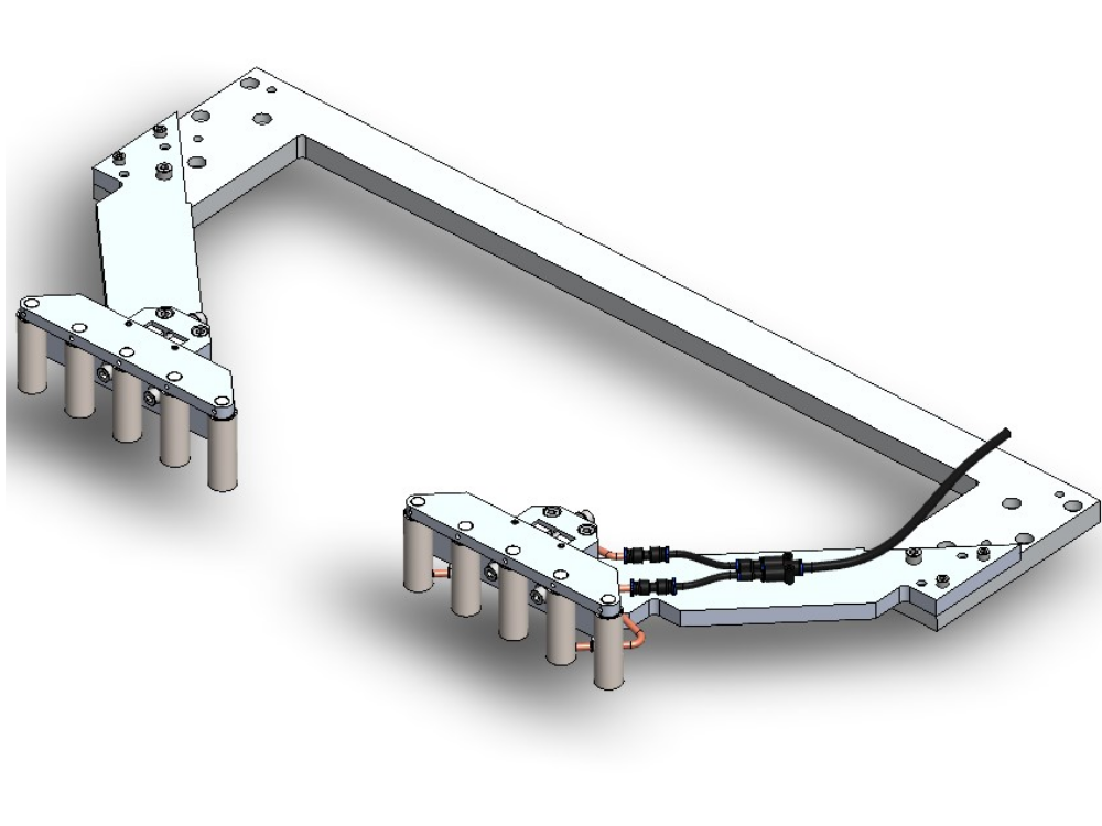
This kit consists of 2 new back fences (left and right hand) with adjusters and mounting arms that are supplied pre-built.
Tools Required
- 5mm Hex Wrench
- 6mm Hex Wrench
- 3mm Hex Wrench
- 2.5mm Hex Wrench
- 1.5m Straight Edge
- Engineer's Square
Adjustment Axes
Installation and Setup
1. Before starting check that the saw head frame is square to the cabinet base and runs in a parallel motion.
2. Remove the existing backfences and arms. Do not remove the dowel pins from the Clamp Support Strut.
3. Fit the new back fences in place using the mounting holes/dowel pins in the Clamp Support Strut.
4. Follow the steps in the order below to align the backfences:
| Step | Pic | |
|---|---|---|
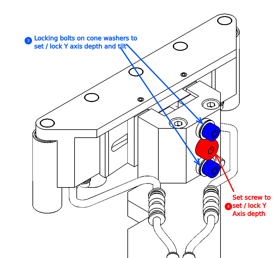
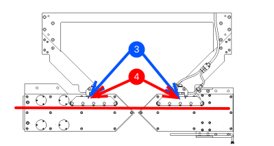
| 1 | Make perpendicular to saw tables using rear M8 adjusting screws (3 and 4). | 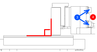 |
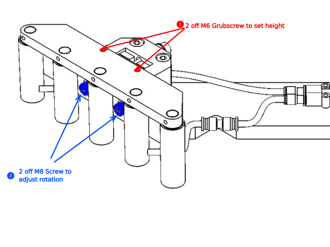
| 2 | Set the height above saw tables with the 2x M6 grubscrews (1) on the top of the roller mount (Slightly loosen the front M8 adjustment screws first). | 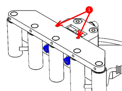 |
| 3 | Make parallel to the X-axis using by loosening the front M8 adjusting screws (2) and then pushing the convex infill plate to the required position. Re-tighten the screws.
|
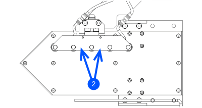  |
| 4 | Double Check that the backfences are still perpendicular to the saw tables. (as in Step 1) | |
| 5 | Aim the blowers so that they push any profile offcuts into the waste chute. |
Software Setup
1. Find the minimum SY position.
2. Check that there are no deep Y notches on narrow profile.
3. check Saw Cut positions are bigger than minimum SY position.
Draft
 Français
 English
 Deutsch
 Español
 Italiano
 Português