How to use the rackOffset features in v6.4.37.0 to correct incorrect linearity on a gripper rack


Difficulté
Très difficile
Durée
1 jour(s)
Sommaire
- 1 Introduction
- 2 Étape 1 - Temperature Warning
- 3 Étape 2 - Choose your yardstick and check linearity
- 4 Étape 3 - Ensure your measuring equipment matches the calibration
- 5 Étape 4 - Create Linearity Test Bars
- 6 Étape 5 - Check Consistency
- 7 Étape 6 - Measure position of each slot from datum end
- 8 Étape 7 - Find the actual positions of the operations
- 9 Étape 8 - Add operation positions and offsets
- 10 Étape 9 - Test again
- 11 Étape 10 - More information
- 12 Commentaires
Introduction
Accuracy problem on A2001 was traced to a non-linear rack. This tutorial demonstrates how to test the linearity of a rack and the systems in place to correct the linearity.
Étape 1 - Temperature Warning
Maintaining a constant bar temperature is incredibly important during these tests. Profile grows 0.07mm per metre per degree of temperature rise, so if you source a test bar from outside at 0 degrees, then the machine is near a heater at 20 degrees, a 6m bar will have grown by 8.4mm as it heats up! given that we will be measuring increments of 0.25mm, this is serious...
The simple solution is to ensure the bars are at room temperature before you start. Keep the doors closed during the tests. Keep an eye on the overall length of the bar by using the same measuring tape

Étape 2 - Choose your yardstick and check linearity
It is vital that you use a measuring tape that is linear in scale, and reasonably accurate. It is even more important that you use one (AND ONLY ONE) measuring tape throughout this test. It is not critical that the tape is 100% accurate - that is impossible - but what is important is that you consistently use the same tape.
The linearity of the tape can be checked using a simple process
- Using the distance between 100mm and 1100mm, make out a "Standard" metre on a flat, solid, consistent surface (use 100mm and 1100mm to ensure there is no error at the zero point
- Check the zero point is consistent - discard the tape measure if it isn't, it will be a pain otherwise
- Check the areas 1000-2000mm, 2000-3000mm, etc against the "standard" metre
It could be the case that your "standard" metre is not really a metre exactly, but that does not matter. What is important is that a metre means the same thing all the way along the tape. That is linearity

Étape 3 - Ensure your measuring equipment matches the calibration
- Cut a long bar length - as long as you can given the standard length and capacity of the machine. In our test we used 5m bar lengths cut from 5.3m standard lengths
- Measure bar length to your chosen tape rule.
- Adjust the scaling of the machine to ensure the cut bar is 5m long +/-0.5mm
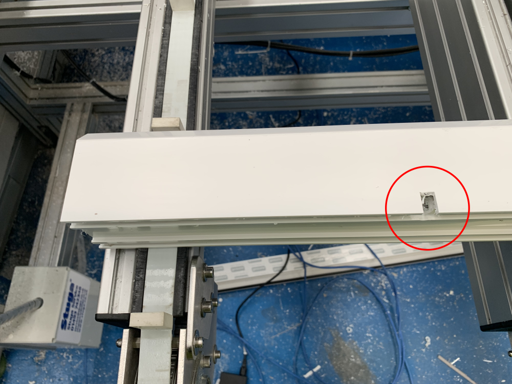
Étape 4 - Create Linearity Test Bars
- Create THREE manual input pieces 5m [] and add the "Calibration Notch" at 250mm intervals from 250mm to 4750mm
- Run all 3 bars


Étape 5 - Check Consistency
Compare the position of the slots on each of the 3 bars with respect to each other. by lining the up together (regrettably photo does not show this)
If the 3 bars are not identical, the root cause is not linearity.
Do not proceed with this process, the root cause will be mechanical play in
- Clamping
- Gripping
- Alignment
- Loose Components
Or possibly drive tuning
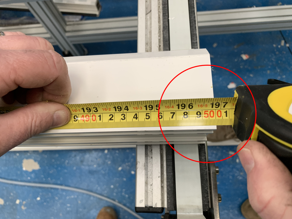
Étape 6 - Measure position of each slot from datum end
Write the error +\- next to each notch, measuring from machining centre end (photo shown is RtoL feed machine).
Repeat for each notch on each of the 3 bars
Again, check for consistency. If there is any doubt that the results have not repeated consistently 3 times, then do not proceed


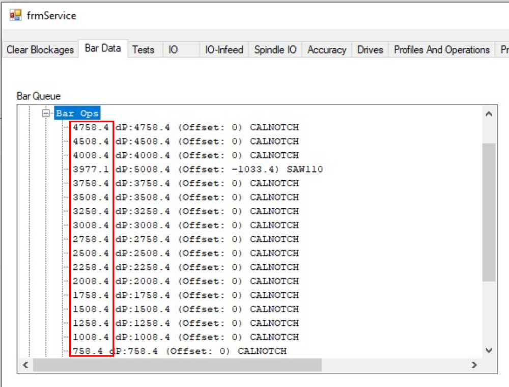
Étape 7 - Find the actual positions of the operations
In the Service Form->Bar Data you can find the operation positions in the bar tree
You only need the CALNOTCH positions, not the saw cuts
Étape 8 - Add operation positions and offsets
Add the positions from the step above along with the offsets
Press Save

Étape 9 - Test again
Run the linearity test from above again.
Success will be all the notches in the place they should be with no discernable offset
Étape 10 - More information
Draft
 Français
 English
 Deutsch
 Español
 Italiano
 Português