How to set up the cranks mechanically so the correct overlaps and limits are achieved.
Sommaire
- 1 Introduction
- 2 Pièces et outils
- 3 Étape 1 - Programme Eaton Drives.
- 4 Étape 2 - Set idler and tighten clutches
- 5 Étape 3 - Set mechanical end stops
- 6 Étape 4 - Roughly set sensor positions
- 7 Étape 5 - Check crank directions
- 8 Étape 6 - Set minimum and maximum positions
- 9 Étape 7 - Check overlaps between the different racks
- 10 Étape 8 - Lock off sensors and mechanical end stops
- 11 Commentaires
Introduction
This tutorial will show you how to mechanically set up the cranks and sensors so that the correct overlaps between the different cranks are achieved.
Crank C is the crank on the Machining Centre Outfeed that controls the single pop up.
Crank D is also mounted on the Machining Centre Outfeed and controls the pop ups on the Transfer Table.
Crank E is the crank on the Saw Infeed and controls the single pop up that moves the profile in to the channel.- Pièces et outils
Pièces et outils
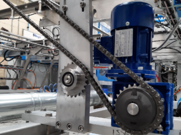
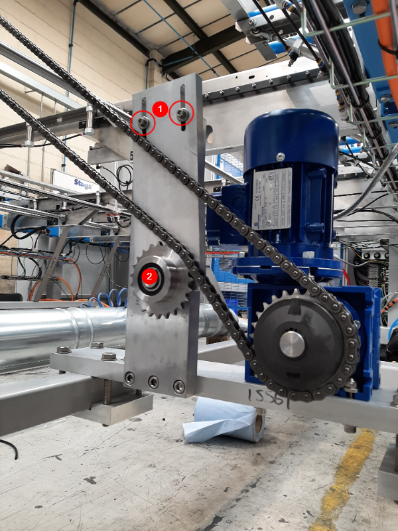
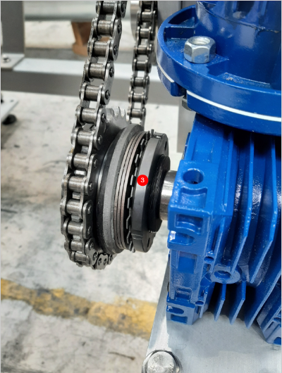
Étape 2 - Set idler and tighten clutches
- Loosen the two bolts holding the idler
- Adjust until the idler sprocket is applying some pressure to the chain
- Use a C spanner or a hammer and drift to tighten the clutch.
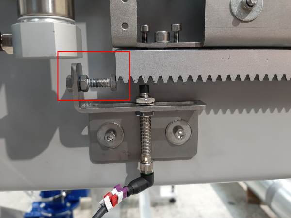
Étape 3 - Set mechanical end stops
These mechanical end stops should only ever be used as a fail safe in cases of sensors failing. These should be set so that the gears can never come off the racks.
Étape 4 - Roughly set sensor positions
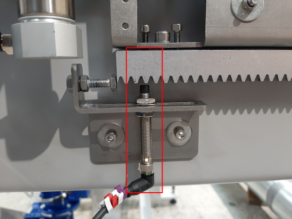
Using a pair of 13mm spanners, nip the proximity sensors in place so that they are roughly in the middle of the slot.
Do this for all 6 sensors (2 on each assembly - 1 'home' and 1 'out')
Étape 5 - Check crank directions
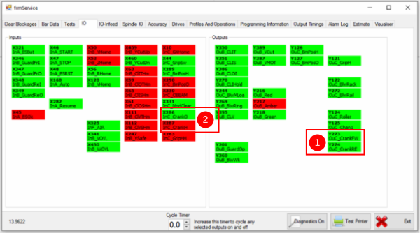
- Using the outputs (1) run the crank in forward and reversing movements
Étape 6 - Set minimum and maximum positions
Moving the sensor left and right on the slot will change the distance the crank travels. The aim here is to stop the rack before it hits the mechanical end stops.
You may have to run the cranks backwards and forwards a few times to get these right.
The aim is for the gap between the end stop and the rack to be between 3mm and 8mm each time. IT MUST NOT BOTTOM OUT
Étape 7 - Check overlaps between the different racks
It is important to get the overlaps between the cranks correct so that the profile is transferred smoothly from one module to the next and to also avoid collisions between the grippers and the pop ups.
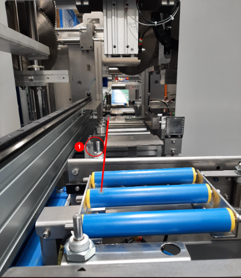
- Crank C 'Home' position (1) needs to be behind the backfence
- Crank C 'Out' position needs to overlap Crank D 'Home' position
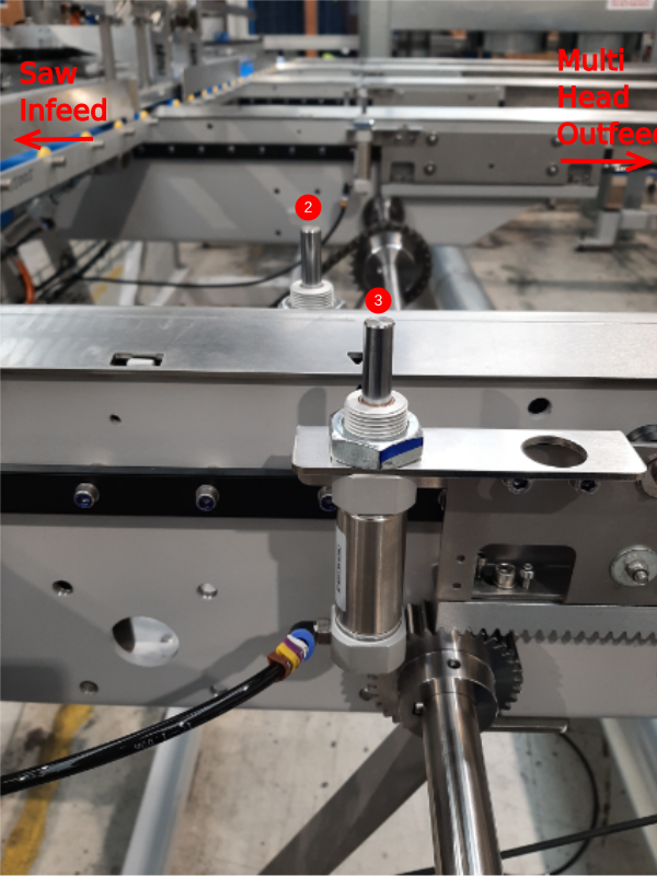
- Crank D 'Out' (2) position needs to overlap Crank E 'Home' (3) position
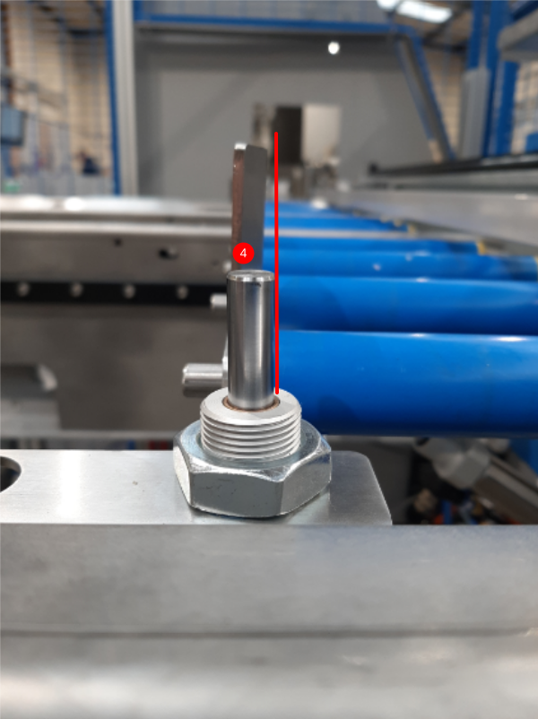
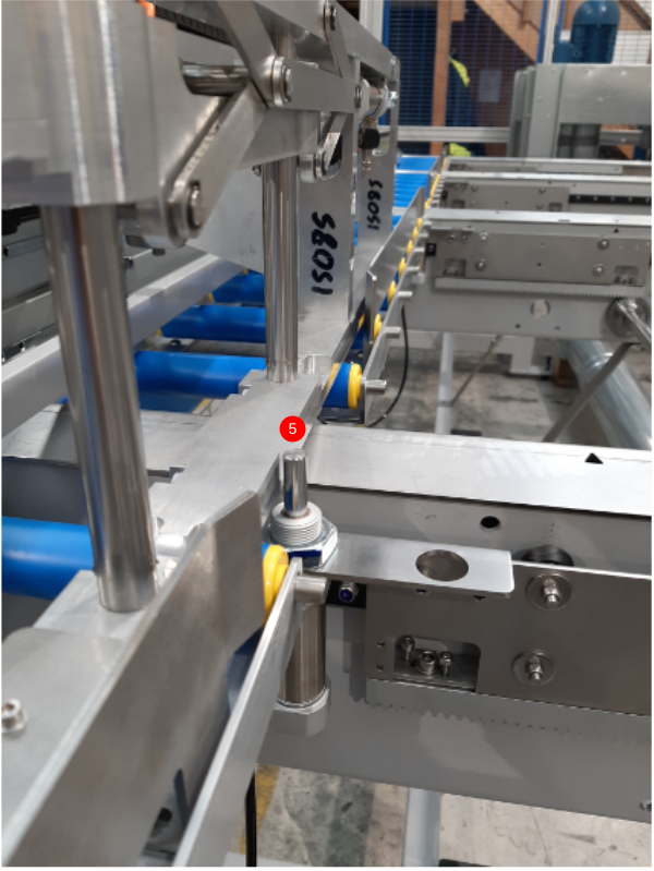
- Crank E 'Out' position (4) needs to sit in front of the Saw Infeed backfences but not so far forward that it will be hit by the gripper (5)
Étape 8 - Lock off sensors and mechanical end stops
Draft
 Français
 English
 Deutsch
 Español
 Italiano
 Português