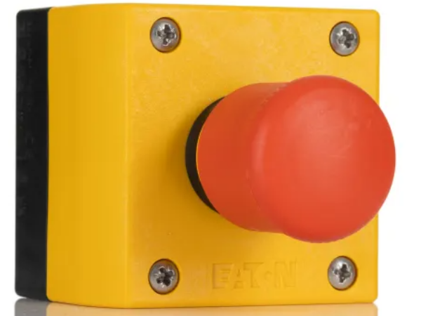
A guide on how to fault find an emergency stop circuit fault on any Stuga machine.
Introduction
Étape 1 - Purpose of the Safety Circuit
A machinery safety circuit is designed to protect both the equipment and operators from harm by ensuring safe operation. It monitors critical safety functions, like emergency stops, protective guards, and sensors, to prevent accidents or malfunctions. In case of a failure or hazard detection, the circuit triggers shutdowns or alerts, ensuring that the machine operates within safe limits and reduces the risk of injury or damage.
Étape 2 - Different Types of Safety Circuits
Safety Relay Controllers: These are used to monitor safety devices like emergency stops, interlocks, and door switches. They ensure that the machine stops or enters a safe state when a fault or hazardous condition is detected. This is a hard-wired system using either a single or double channel loop and can have a feedback loop hard-wired into the system with a manual restart button. This system is the most commonly used in the Stuga machinery range.
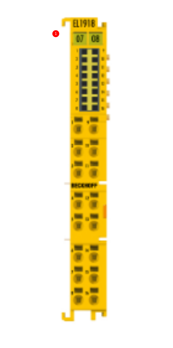
Safety PLCs (Programmable Logic Controllers): These are specialised PLCs designed to handle safety applications. They provide high levels of safety and redundancy and can integrate both standard control tasks and safety control tasks in the same system, making them suitable for large, complex machinery. We have a number of machines that use a programmable safety system which is know as 'TwinSAFE' and is built into the Beckhoff EtherCAT system. These can be identified in the IO blocks of machine cabinets and have a yellow finish.
Other: There are lots of different types of safety circuit controllers that can be find on different machines. Some of these controllers are very basic and others are very complex.
Étape 3 - Identifying Different Circuits
Picture 1: This is a safety IO slice and is part of the Beckhoff TwinSAFE system.
Picture 2: This is a safety relay which was used on Flowlines and Early ZX machines. This relay can be found in the Saw Infeed (Transfer) cabinet. This relay is typically wired as a single channel loop.
Picture 3: This is a safety relay which was used on Standalone Saws. This relay can be found in the main console electrical cabinet. This relay can vary in colour and some examples of this are blue and yellow. Again, this relay was typically used for a single channel loop. **PICTURES REQUIRED**
Picture 4: This is a safety relay which was introduced on Autoflow 2 machines and then used on ZX5's. This relay can typically be found in the Infeed cabinet on either machine. It is yellow in appearance which makes it prominent inside the cabinet. This relay is used for dual channel loops. **PICTURE REQUIRED**
Picture 5: This is a safety relay which was introduced on later ZX5 machines and now used in all applications from new builds to refurbs. This relay can typically be found in the Infeed cabinet. It is yellow in appearance which makes it prominent inside the cabinet. This relay is used for dual channel loops and provides additional diagnostics and settings on the unit front. **PICTURE REQUIRED**
Étape 4 - Principles of a 'Loop/ Channel'
**Do not use this section for theTwinSAFE system**
The fundamental wiring behind any single or dual channel safety relay is the 'e-stop loop'.
The 'e-stop loop' is a term used for the start and end of the safety circuit. Some systems have 1 loop (single channel) and some have 2 (dual channel). The 'loops' start and end at the safety relay. The most basic funtion of the safety relay is to send out a signal from one of its terminals and if it receives the same signal back on another terminal, it evaluates the circuit as safe. This can be seen in Picture 1. Picture 2 has the same principle, however, the safety relay is now evaluating 2 loops rather than 1. In both pictures, notice there is only 1 safety device connected. In this case, an emergency stop button. In a dual loop circuit, one of the loops is typically low voltage (0v) and one loop is typically high (10-24V).
Étape 5 -
Draft


 Français
 English
 Deutsch
 Español
 Italiano
 Português