Assembly details for conveyor frame

Difficulté
Moyen
Durée
4 heure(s)
Sommaire
- 1 Introduction
- 2 Étape 1 - Unless otherwise stated
- 3 Étape 2 - Handing
- 4 Étape 3 - Drill blower points on rollers
- 5 Étape 4 - Assemble mounts
- 6 Étape 5 - insert M4 plate nuts
- 7 Étape 6 - Assemble main frame
- 8 Étape 7 - Finalise all fasteners
- 9 Étape 8 - Fit Slave roller (non driven)
- 10 Étape 9 - Fit drive roller
- 11 Étape 10 - Attach adhesive tape
- 12 Étape 11 - Quality Check
- 13 Étape 12 - Fit stainless top plates
- 14 Étape 13 - Fit belt
- 15 Étape 14 - Fit mid rollers
- 16 Étape 15 - Tension drive roller
- 17 Étape 16 - Tension slave roller
- 18 Étape 17 - Check all fasteners
- 19 Étape 18 - Fit drive motor and flange
- 20 Étape 19 - Fit blower fittings
- 21 Commentaires
Introduction
Tools Required
standard hex key set
Standard spanner set
Standard HSS drill set
Standard tap set
Utility knife
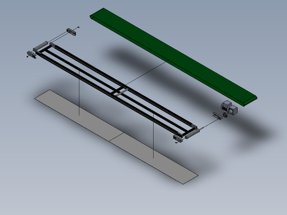
Parts Required
B0000441 Conveyor 3580mm x 300mm x 1
B0001013 Conveyor Motor SEW - WA 10 x 1
B0001177 Pair conveyor side cheeks and bearings slave x 2
M0000133 Conveyor Belt XL-AS 7350 x 300 B x 1
P0000200 Elbow Adaptor 6mm - M5 x 3
Étape 1 - Unless otherwise stated
Use Loctite 243 on all fasteners
Use Loctite 572 on all threaded pneumatic connection
Pen mark all fasteners to show finalised

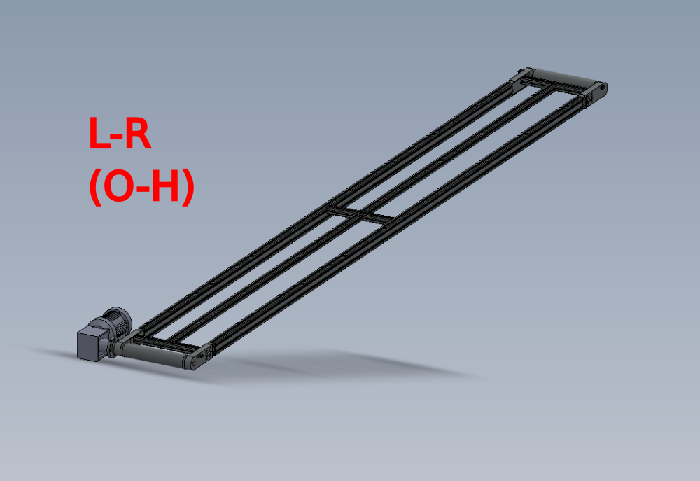
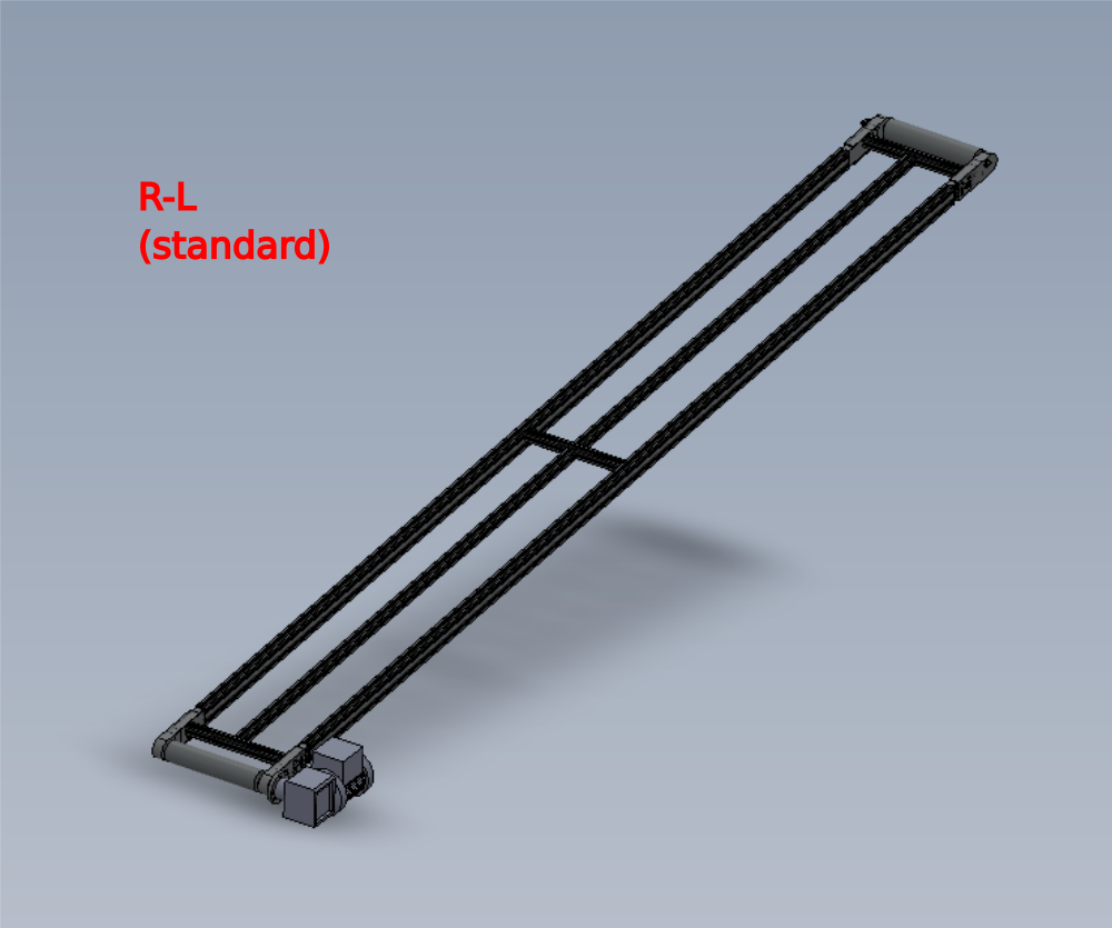
Étape 2 - Handing
Conveyor can be built in 2 formats
L-R
R-L
Please see picture for clarification of orientation
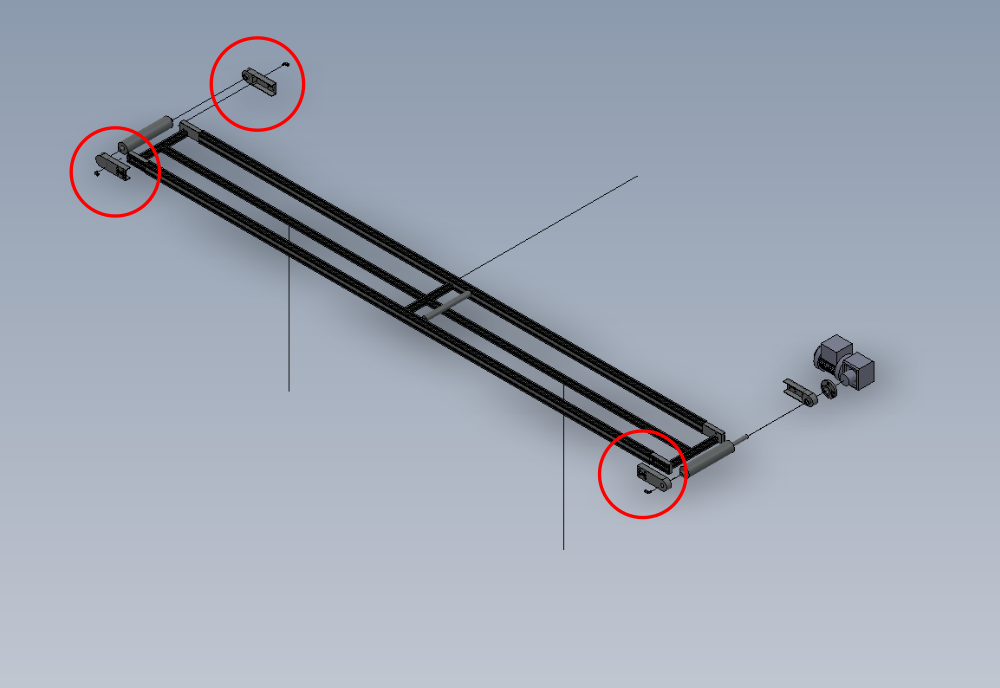
Étape 3 - Drill blower points on rollers
indicated 3 roller housings will require blower holes adding
Mark Blowers as shown .
Drill through with 2.5mm drill
Then drill half way from outside face with 4.2mm drill
Then tap outside face shown M5


Étape 4 - Assemble mounts
Assemble 4 off mounts
Ensure maytec fittings are orientated correctly
Ensure spring clip is fitted to D nut


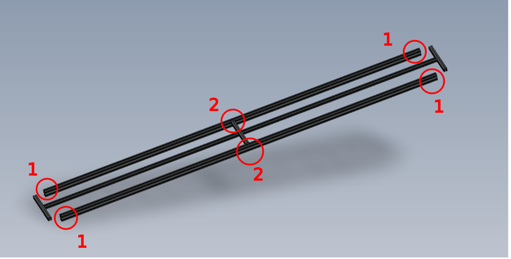
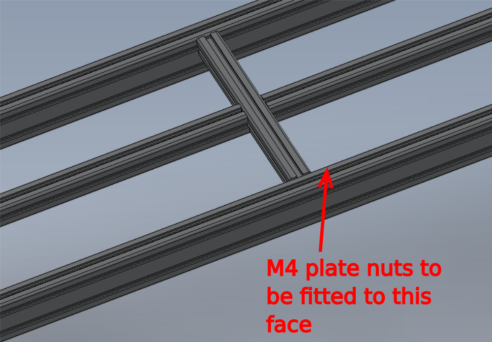
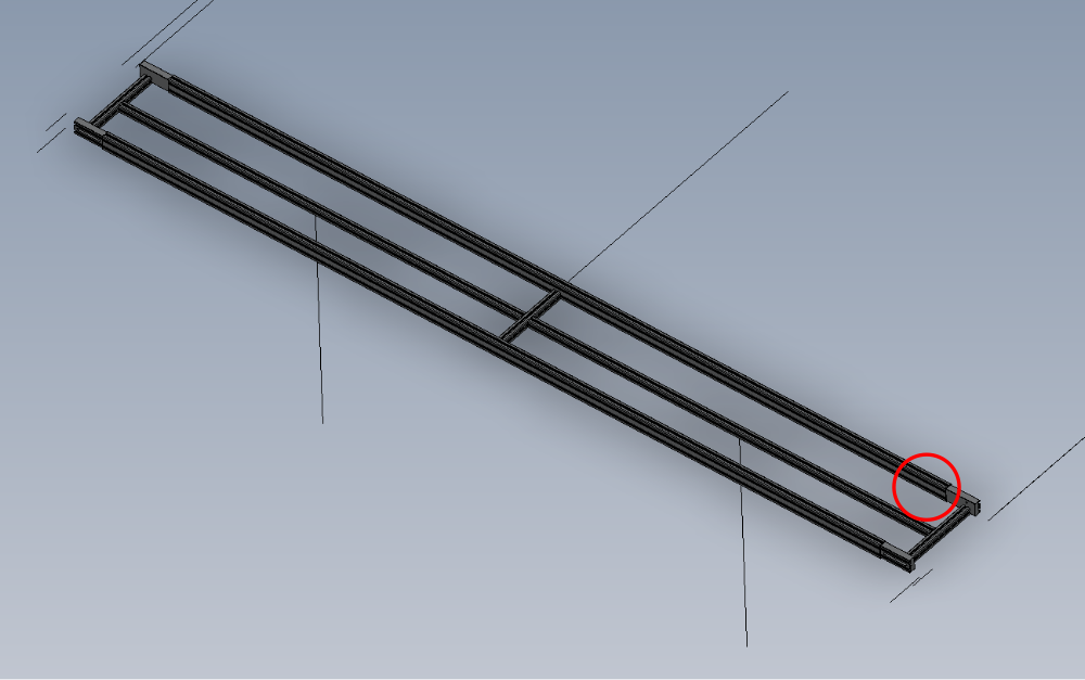
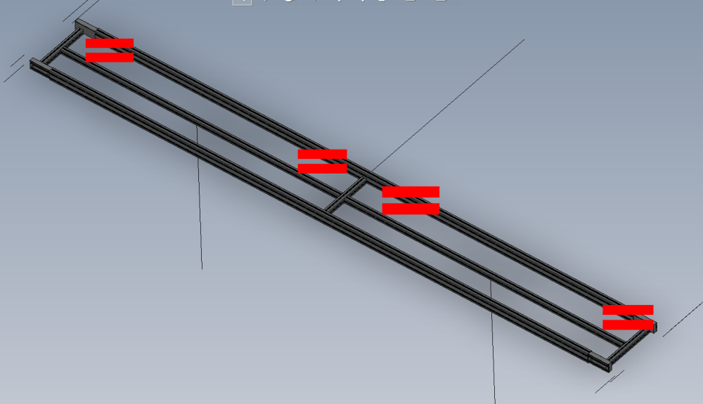
Étape 5 - insert M4 plate nuts
insert 8 off supplied m4 plate nuts into correct face of long frame sections
4 off per side

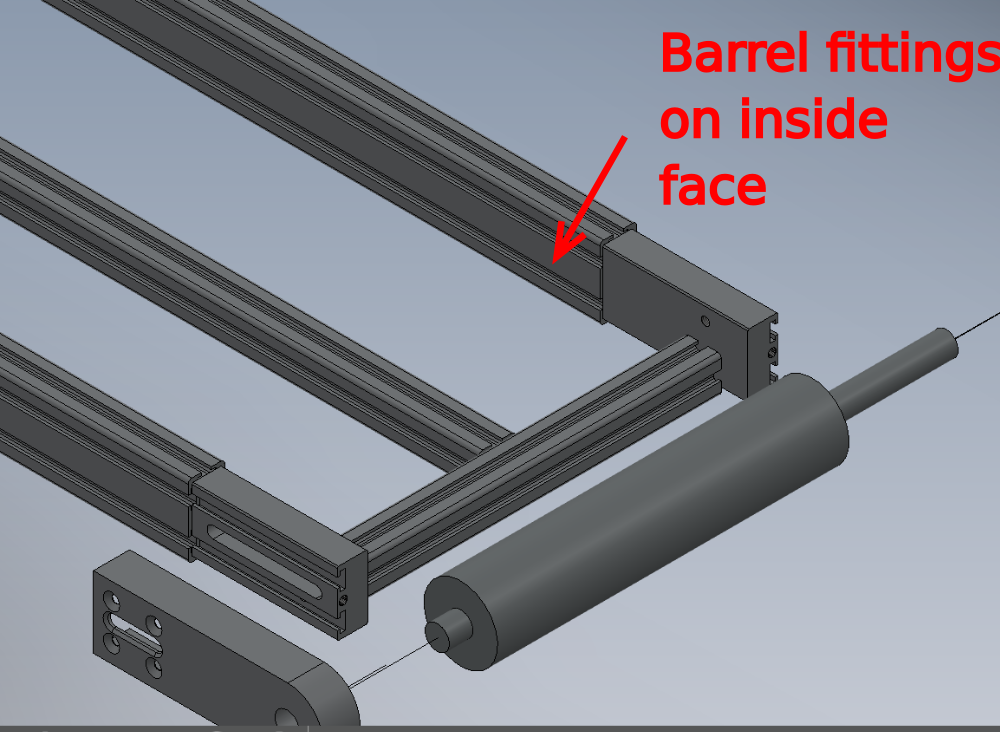
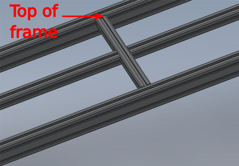
Étape 6 - Assemble main frame
Assemble main maytec frame
Ensure all sections are set in a parallel position
Please capture pictures for this please
Étape 7 - Finalise all fasteners
Ensure all fasteners are finalised on frame

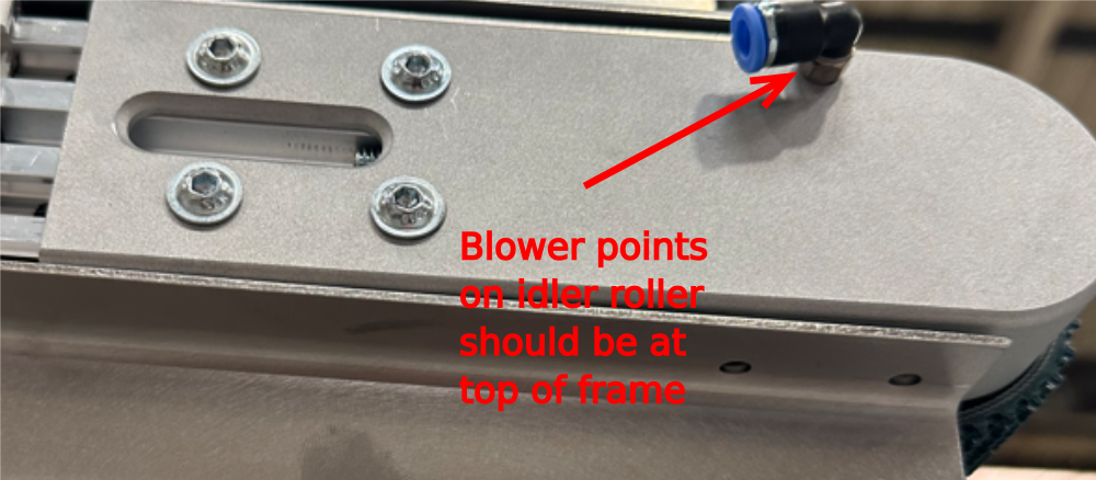
Étape 8 - Fit Slave roller (non driven)
Fit slave roller assembly as shown
Ensure spacer washers are fitted
Ensure blower points are orientated correctly to suit belt rotation direction

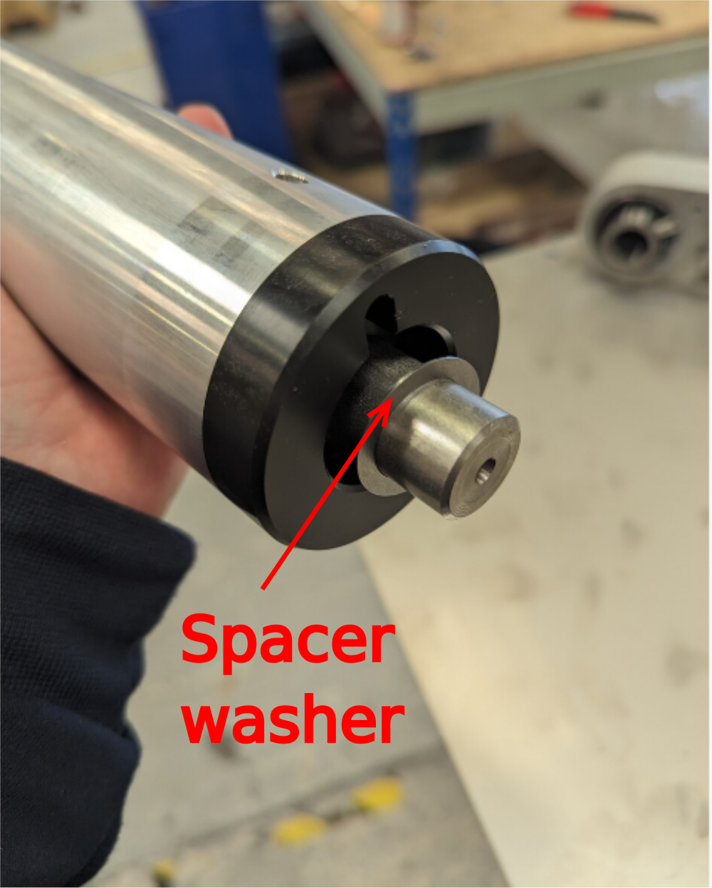
Étape 9 - Fit drive roller
Fit drive roller assembly as shown
Ensure spacer washers are fitted
Ensure blower point is orientated correctly to suit belt rotation direction
Should be at bottom of frame on opposite side of drive motor


Étape 10 - Attach adhesive tape
Fit supplied adhesive tape to top face of frame at shown points
Photos required in correct sequence please


Étape 11 - Quality Check
Check issued stainless plates 2 off have been countersunk correctly
M4 countersunk should sit flush, not above top of stainless sheet

Étape 12 - Fit stainless top plates
Use stainless plates as a guide to align M4 plate nuts before removing adhesive tape backing
Once aligned , remove adhesive tape backing and secure stainless plates into position
Fit 8 off supplied m4 countersunk hex sockets to finalise stainless plate fitting

Étape 13 - Fit belt
Fit belt to assembly
Photos required in correct sequence please

Étape 14 - Fit mid rollers
Fit mid rollers


Étape 15 - Tension drive roller
Set lower roller tension (motor end)
Measure and set gap to 15mm either side
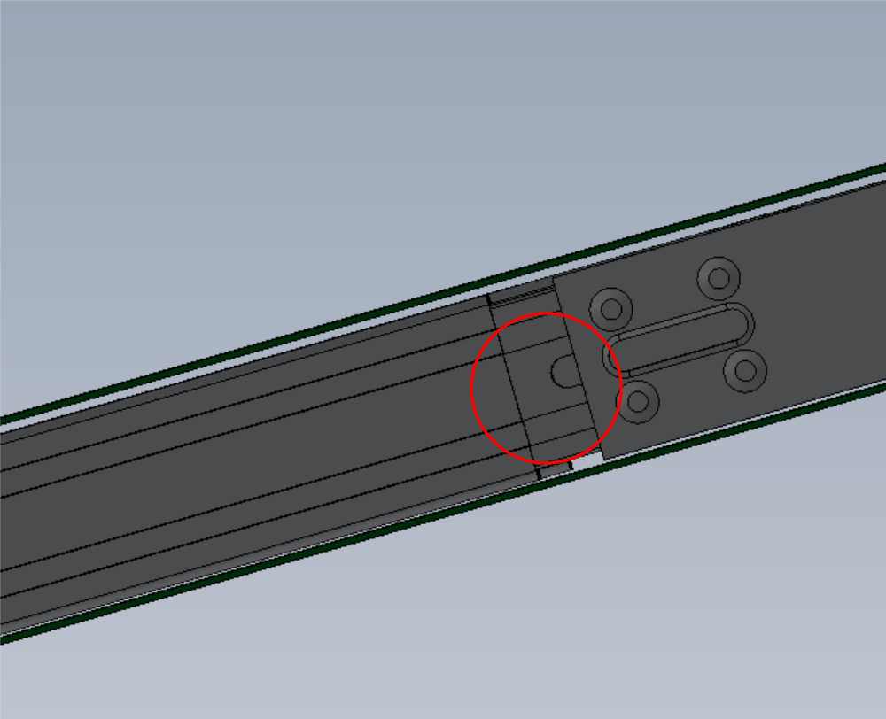
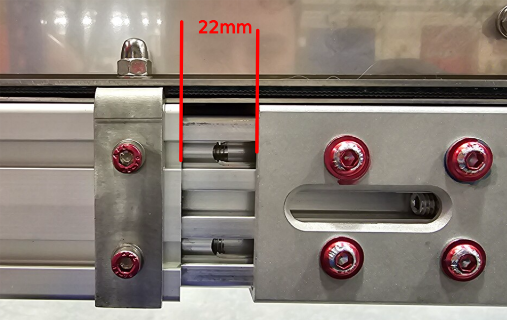
Étape 16 - Tension slave roller
Tension drive roller to 22mm gap at both sides of roller
Ensure both sides are set to the same measurement

Étape 17 - Check all fasteners
Quality check all fasteners
ensure all fasteners have adhesive applied, are correctly tensioned and are pen marked to indicate finalised
Étape 18 - Fit drive motor and flange
Fit drive flange to bearing cheek ensuring correct orientation to allow correct fitment of motor
Fit motor to bearing flange, do not apply final tension or adhesive to locating grubscrew as motor will need to be removed later on
It is important to test fit at this stage to identify correct fitment


Étape 19 - Fit blower fittings
Fit 3 off blower fittings to mounting points on bearing cheeks


Draft
 Français
 English
 Deutsch
 Español
 Italiano
 Português