Alignment process and criteria for module A aligning to module B

Difficulté
Difficile
Durée
2 heure(s)
Sommaire
- 1 Introduction
- 2 Étape 1 - Position module A
- 3 Étape 2 - Level Y axis
- 4 Étape 3 - Level X Axis
- 5 Étape 4 - Adjust height of module A
- 6 Étape 5 - Backfence Alignment check
- 7 Étape 6 - Backfence alignment adjustment
- 8 Étape 7 - Finalise Height
- 9 Étape 8 - Quality check
- 10 Étape 9 - Fit Light Curtain
- 11 Étape 10 - Fit light curtain to buffer bar
- 12 Étape 11 - Fit light curtain to Module B
- 13 Étape 12 - Connect main air Feed
- 14 Commentaires
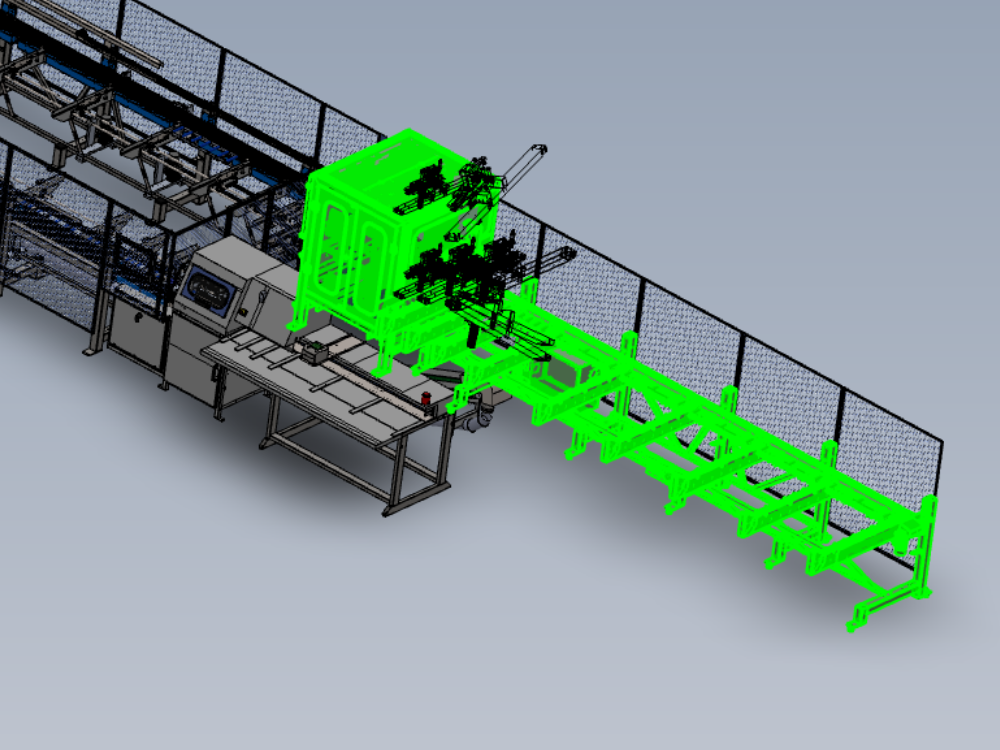
Introduction
Details and steps for correct alignment of Module A to Module B
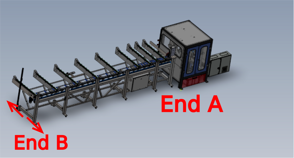
Étape 1 - Position module A
Position module A in front of module B
Use Infeed back fence to Multi head datum rollers as initial alignment guide for Y axis
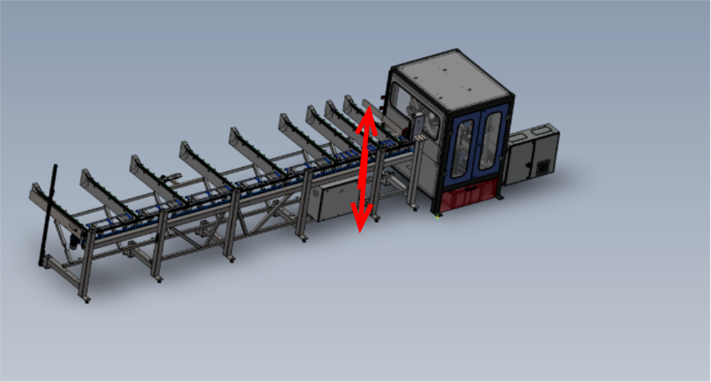
Set gap of 23mm -+ 2mm between module A roller frame and module B roller block


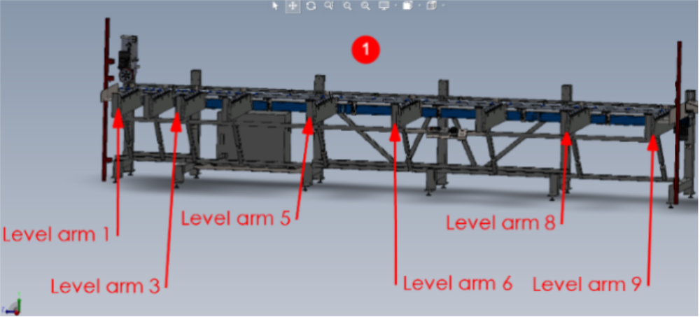
Étape 2 - Level Y axis
1 Use green strip on indicated loader arms and yellow 1 meter level to read level of arms indicated
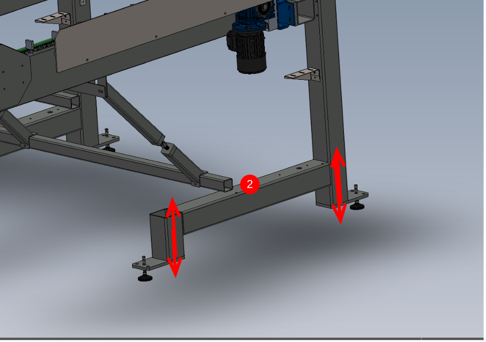
2 Adjust level of arms using jacking points below.
Recheck all levels on arms are correct once final arm has been adjusted

Étape 3 - Level X Axis
1 Use module B horizontal datum rollers to position laser level on
2 Cast Beam from laser along infeed frame approximately 30mm away from back fence
3 Take measurement on arm closest to module B at the indicated point from green runner strip to laser line
4 Adjust at each adjustment point to set each measurement to the same as the first measured arm
Ensure adjustment points are altered in pairs with exact turns to ensure Y axis level is not lost


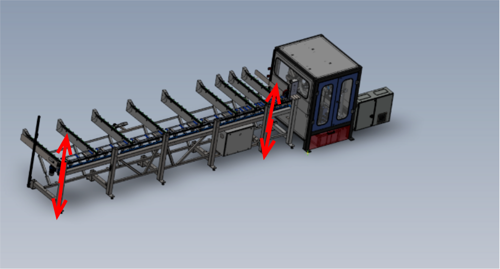
Étape 4 - Adjust height of module A
Module A height must now be adjusted to match the height of Module B datum rollers
Ensure the adjustment points are always turned the EXACT same rotation when adjusting. This will ensure that Y axis level is not compromised
Adjust height to match height of Module B datum rollers. Tolerance -+1mm
Étape 5 - Backfence Alignment check
A laser must be used to ensure the backfence of the infeed is aligned along its entire length
1 Place laser against vertical rollers in module B, casting line over infeed table.
2 Take measurement of laser beam to first backfence closest to Module B
3 Take same measurement at furthest backfence , this will identify the misalignment if present as both figures need to be the same


Étape 6 - Backfence alignment adjustment
To adjust the measurement, the end B of the infeed frame must be moved in the direction required to correct the measurement
Keep adjusting End A and B until the following are correct
Laser measurement is less than 2mm in difference from End A to B
Backfence alignment at End A is 1mm (tolerance -+0.5mm) behind the module datum rollers
Étape 7 - Finalise Height
Height difference between module B datum rollers and infeed rollers should now be finalised
Adjust to set infeed roller 1mm below Module B Datum rollers . Use Jacking points on frame and ensure all points are rotated equally to ensure previous settings remain
Étape 8 - Quality check
Please now quality check all settings for accuracy and correct setting
Step 2 Y axis levels all correct and within sight lines of level
Step 3 X axis level all correct and no greater error
Step 6 backfence alignment . Infeed backfence is set to the correct distance behind Module B datum rollers
Step 7 Rolle height is set to 1mm (-+0.5mm) lower than module B datum rollers

Étape 9 - Fit Light Curtain
Now the modules have been aligned , Safety light curtain should be fitted from
R0015266B
Étape 10 - Fit light curtain to buffer bar

Étape 11 - Fit light curtain to Module B
Fit Light curtain [parts to module B
Étape 12 - Connect main air Feed
12mm blue pipe trailing from infeed table should be connected to module B air service unit
Draft
 Français
 English
 Deutsch
 Español
 Italiano
 Português