Alignment process and criteria for module A aligning to module B

Difficulté
Difficile
Durée
2 heure(s)
Introduction
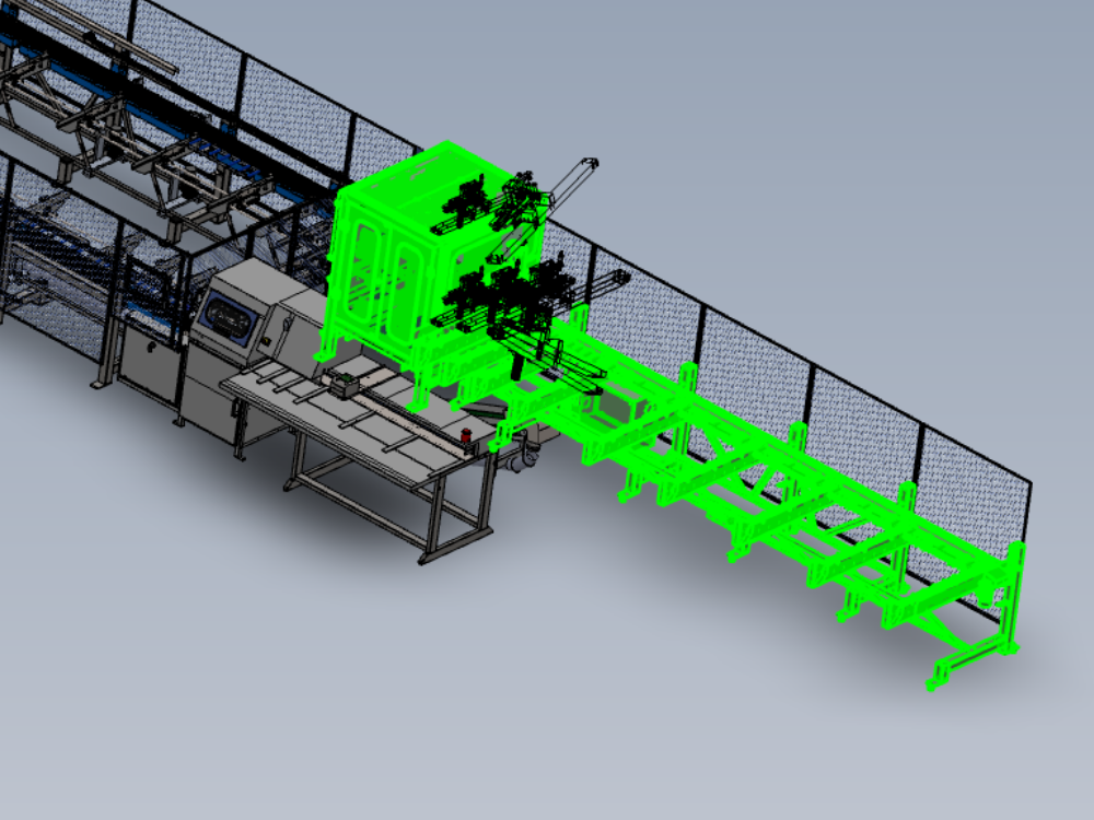
Details and steps for correct alignment of Module A to Module B
Étape 1 - Position module A
Position module A in front of module B
Use Infeed back fence to Multi head datum rollers as initial alignment guide for Y axis
Set gap of 23mm -+ 2mm between module A roller frame and module B roller block


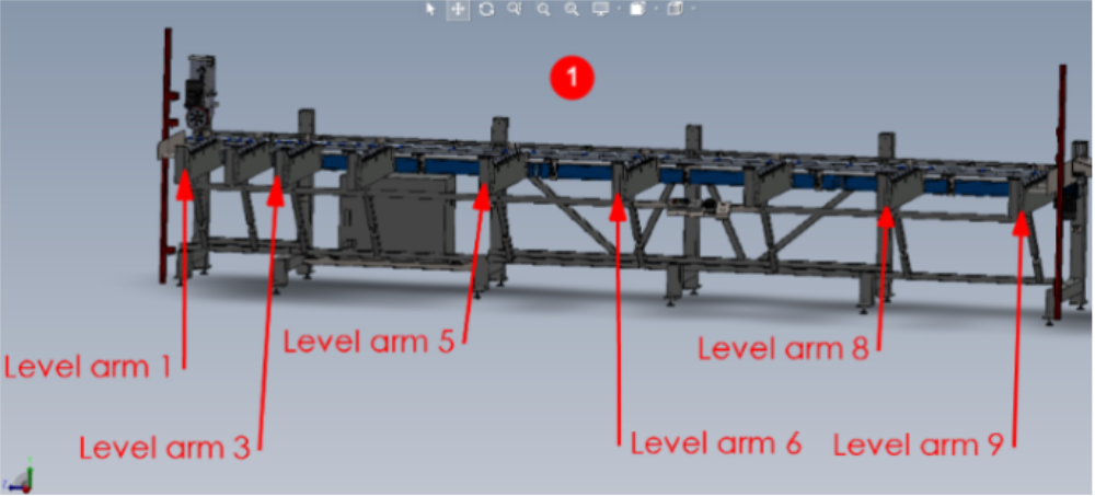
Étape 2 - Level Y axis
1 Use green strip on indicated loader arms and yellow 1 meter level to read level of arms indicated
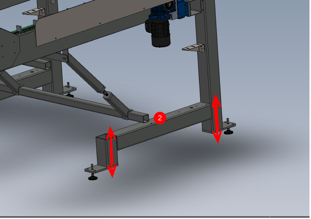
2 Adjust level of arms using jacking points below.
Recheck all levels on arms are correct once final arm has been adjusted

Étape 3 - Level X Axis
1 Use module B horizontal datum rollers to position laser level on
2 Cast Beam from laser along infeed frame approximately 30mm away from back fence
3 Take measurement on arm closest to module B at the indicated point from green runner strip to laser line

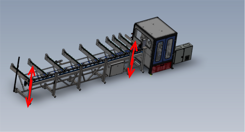
Étape 4 - Adjust height of module A
Étape 5 -
Draft
 Français
 English
 Deutsch
 Español
 Italiano
 Português