Pneumatic function test for Rotary Ring
Sommaire
- 1 Étape 1 - Lubrication
- 2 Étape 2 - Connect air feed
- 3 Étape 3 - Check for air leaks
- 4 Étape 4 - Home positions
- 5 Étape 5 - Home position correction
- 6 Étape 6 - Manual valve activation
- 7 Étape 7 - Test single slide bases
- 8 Étape 8 - Test double slide bases
- 9 Étape 9 - Disconnect air
- 10 Étape 10 - Finalize 4mm looms
- 11 Commentaires
Étape 1 - Lubrication
All lubrication points should be greased
2 pumps of grease to be added to each linear bearing
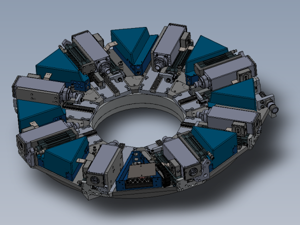
24 off bearings in total
4 off bearings per double slide base
2 off bearings per single slide base
Étape 2 - Connect air feed
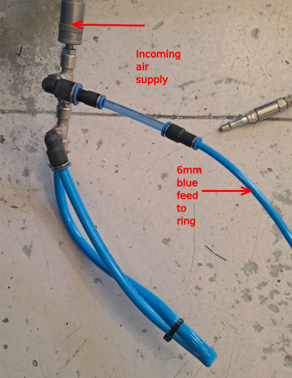
Compressed air feed needs connecting to main 6mm blue feed pipe to ring.
Use adapter to enable safe connection via PCL coupling and probe
Étape 3 - Check for air leaks
When air is connect to rotary ring, attention should be paid to any audible air leaks. If any are present, identify source and rectify
Étape 4 - Home positions
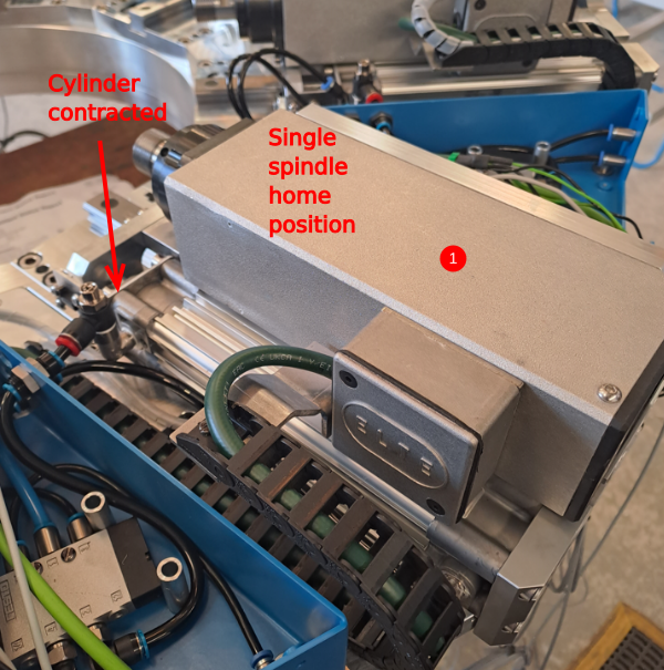
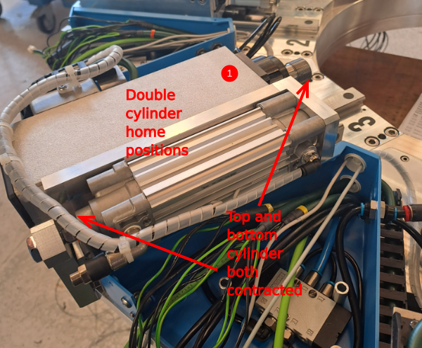
1 When air is connected, all cylinders should be in a contracted state. This is their home position
Étape 5 - Home position correction
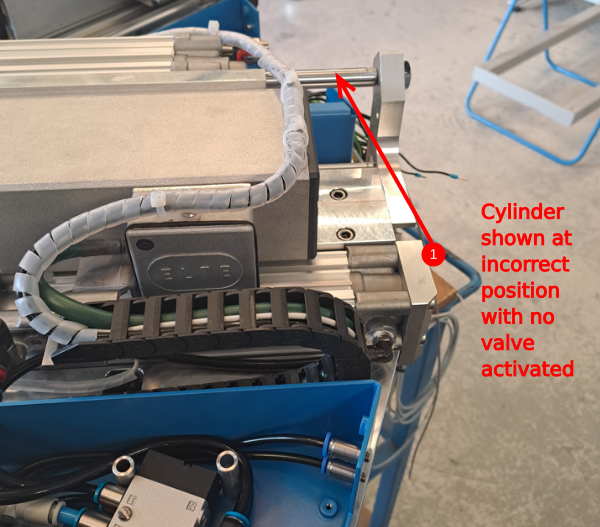
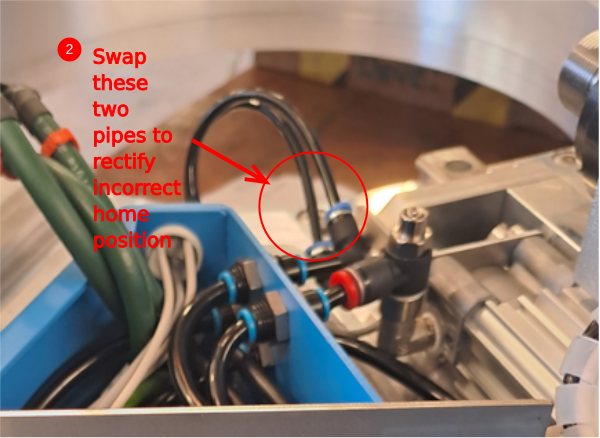
If correct practice has been followed, only the double slide cylinder will have the possibility of being at the incorrect home position . This is easily rectified
1 Image shows incorrect position when air has been connected to mains supply
2 To rectify, disconnect mains air feed and swap the two indicated pipes at the stem elbows
3 Reconnect air and confirm correct home position is now achieved
Étape 6 - Manual valve activation
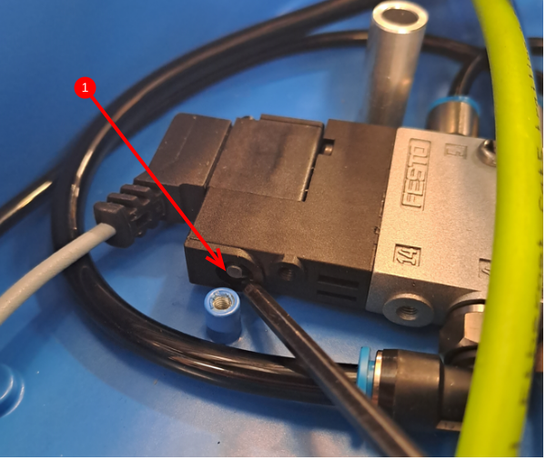
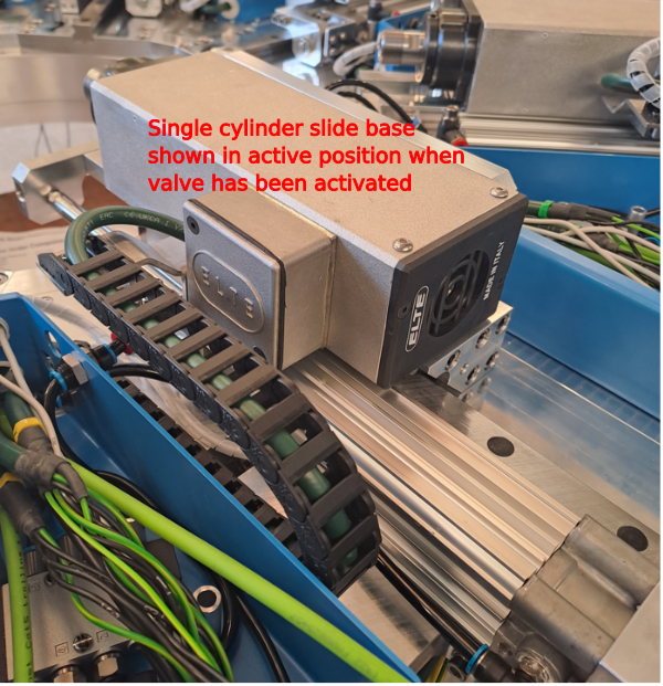
Valves can be activated manually by the control button. When pressed, the valve will fire the associated cylinder to its active position .
1 Manual valve activation button
Étape 7 - Test single slide bases
4 off
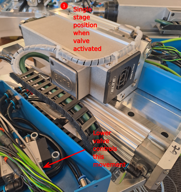
Check that when valve is activated, spindle assembly goes to the position shown. Fire valve a few times to check movement is consistent. Cylinder speeds and cushioning will be set at a later point
Étape 8 - Test double slide bases
4 off
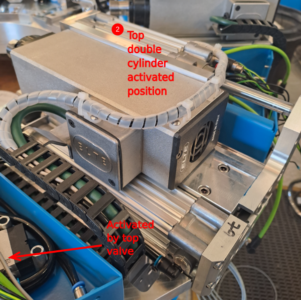
Check that when valve is activated, spindle assembly goes to the position shown. Fire valve a few times to check movement is consistent. Cylinder speeds and cushioning will be set at a later point
1 Single stage cylinder activated by lower valve , see image for details
2 Double stage cylinder activated by upper valve , see image for details
Étape 9 - Disconnect air
Once pneumatic testing is complete disconnect the air supply
Étape 10 - Finalize 4mm looms
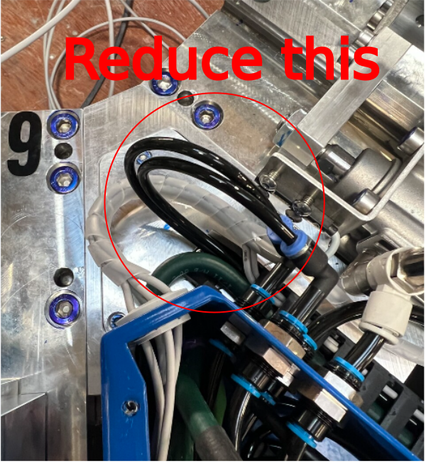
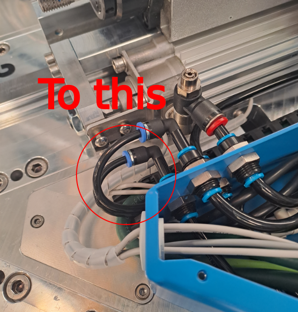
Once testing is complete, oversized 4mm pipe looms can be shortened to the correct length as shown. Loom length should be as minimal as possible to avoid damage
4 off spindles to finalise
Draft

 Français
 English
 Deutsch
 Español
 Italiano
 Português