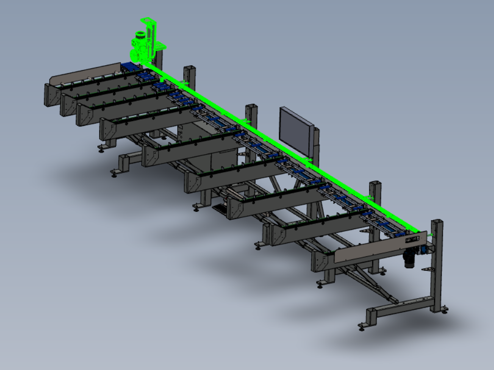
Instructions to mount pre built assemblies to frame

Difficulté
Moyen
Durée
2 heure(s)
Sommaire
- 1 Introduction
- 2 Étape 1 - Unless otherwise stated
- 3 Étape 2 - Attach sensor rail 1
- 4 Étape 3 - Attach sensor rails
- 5 Étape 4 - Mount sensors
- 6 Étape 5 - Mount Loader wheel assembly
- 7 Étape 6 - Adjust position of loader wheel
- 8 Étape 7 - Fit brace 1
- 9 Étape 8 - Fit brace 2
- 10 Étape 9 - Fit keyboard Mount
- 11 Étape 10 - Fit brace 3
- 12 Commentaires
Introduction
Tools Required
Standard hex key set
Parts Required
D0015432 Spacer: Ø25.4 x 100mm (12.7mm ID) x 10
D0015479 Sensor Mount Rail 1450 mm Long x 4
D0015480 Sensor Mount Rail 825 Long x 1
D0015513 Arm brace x 2
D0015514 Arm brace x 1
F0000299 T Nut Sub Insert M6 (Fat) x 16
R0015074 Pre assembled keyboard mount and buttons
R0015030B Bench Assembly Loader Wheel
R0015080 Bench assemble sensor rail
R0015271 Mount buffer bars ( pre fitted to frame )
R0015351 Mount monitor to frame (pre fitted to frame)Étape 1 - Unless otherwise stated
Use loctite 243 on all fasteners
Use Loctite 572 on all threaded pneumatic connections
Pen mark all bolts to show finalised

Étape 2 - Attach sensor rail 1
Use M10 x 120 socket caps to secure sensor rail parts to frame
Attach D0015480 Sensor Mount Rail 825 Long with 2 off D0015432 Spacer: Ø25.4 x 100mm (12.7mm ID)
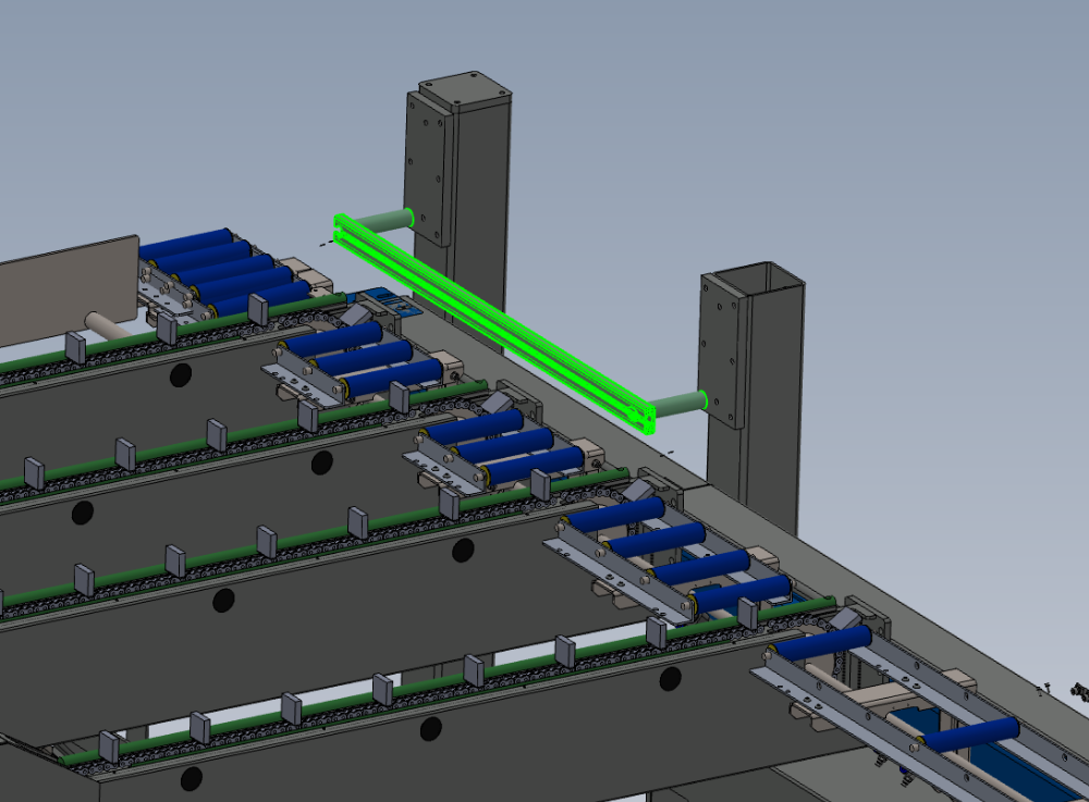
Étape 3 - Attach sensor rails
Use M10 x 120 socket caps to secure sensor rail parts to frame
Attach 4 off D0015479 Sensor Mount Rail 1450 mm Long with 8 off D0015432 Spacer: Ø25.4 x 100mm (12.7mm ID)


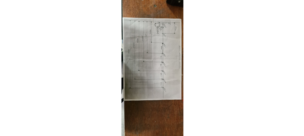
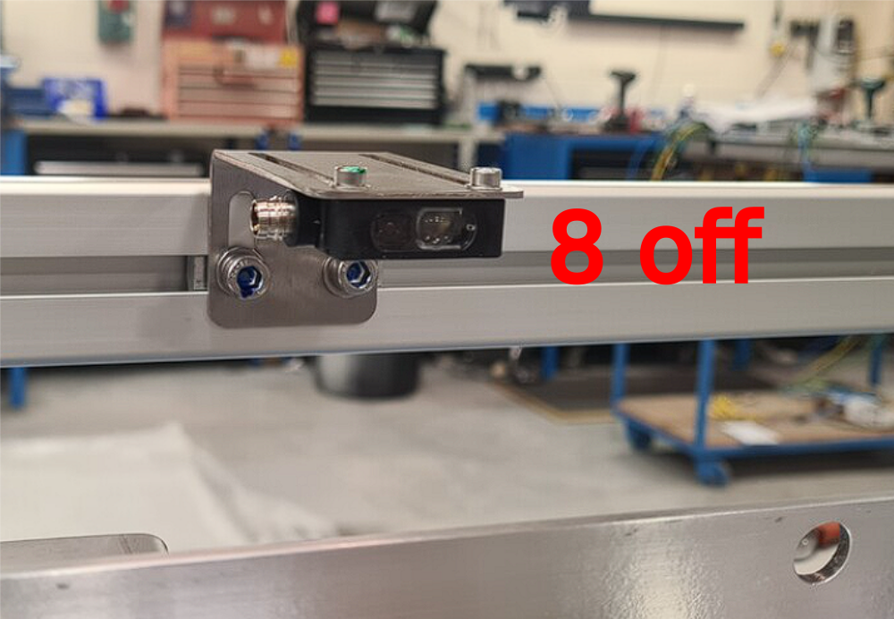
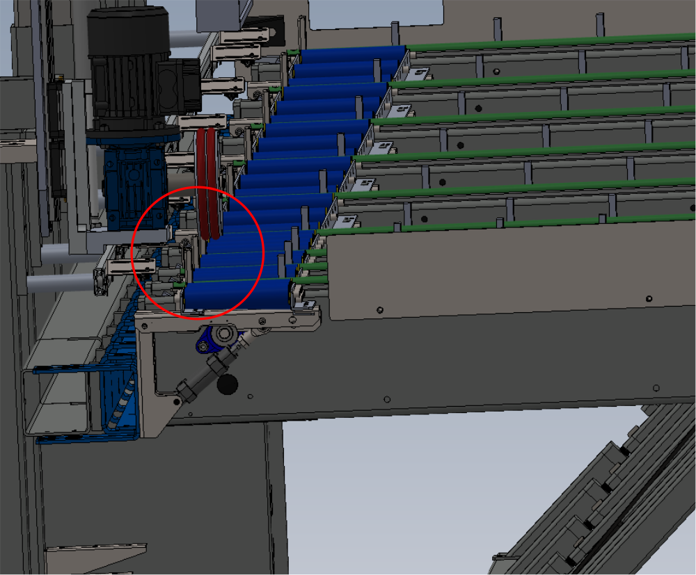
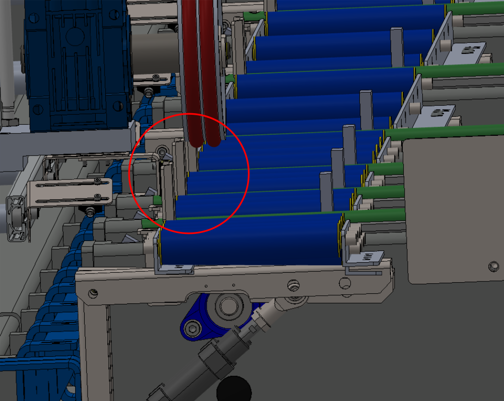
Étape 4 - Mount sensors
Mount sensors from assembly R0015080 with F0000299 M6 D nuts and M6 x 12 socket caps with A form washers
Use Drawing shown for positions , and images for orientation
Ensure drawing is followed for positions of sensors. These measurements are to set the sensors in a standard position. Commission team may alter these on test, but for production adhere to measurements given


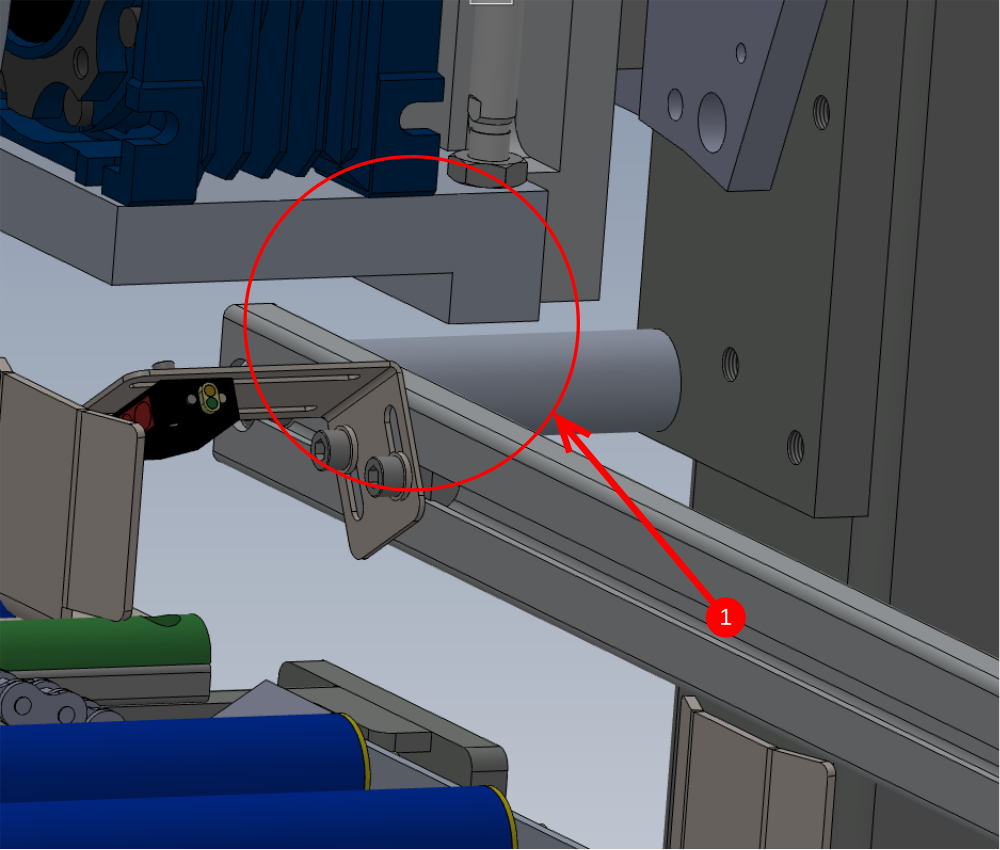
Étape 5 - Mount Loader wheel assembly
Mount loader wheel assemble to frame Using M10 x 30 socket caps with large M10 penny washers (40mm diameter)
Quality check
1 When loader wheel pulley is in its lowest position it must not hit the sensor rail assembly. If contact is evident follow step 2
2 Use Washers as spacers ( size required ) to lift the assembly up from the frame mounting point and create clearance between the loader wheel and the sensor rail

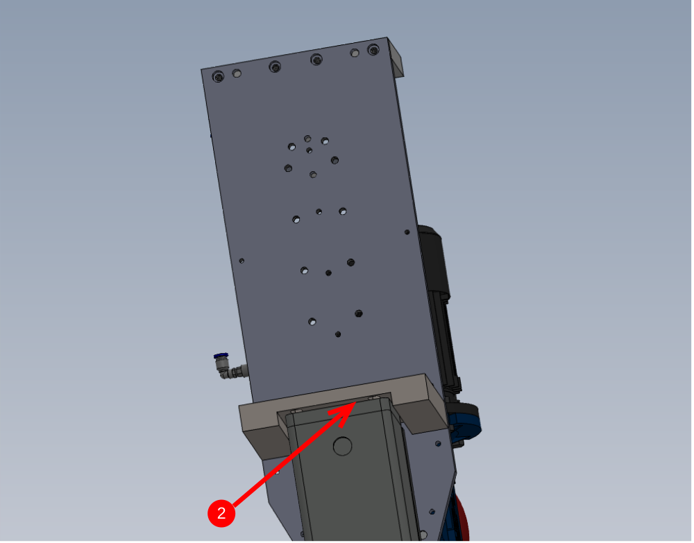
Étape 6 - Adjust position of loader wheel
Set position of loader to 32mm as shown
Measurement is taken from front face of backfence to centre of loader wheel
Finalise fasteners once set

Étape 7 - Fit brace 1
Better picture required please
Fit D0015513 at load motor end of frame .
Use M8 x 35 socket caps, M8 motor plate washers and M8 nyloc nuts .
do not finalise bolts until next section is fitted
Étape 8 - Fit brace 2
Better picture required please
Leave gap for keyboard mount to be fitted, and fit second brace D00155122

Étape 9 - Fit keyboard Mount
Better picture required please
Fit pre assembled keyboard mount R0015074
Fix with M8 35 socket caps , M8 motor plate washers and M8 Nyloc nuts


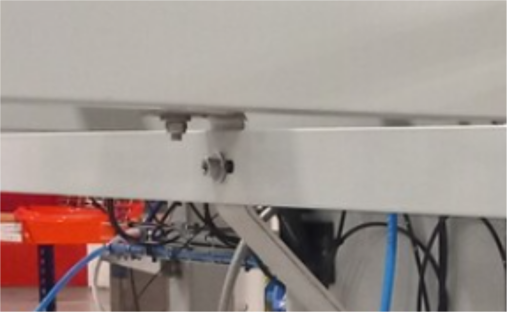
Étape 10 - Fit brace 3
Better picture required please
Fit D0015514 at final position . Add M8 motor plate washer as spacer as shown


Draft
 Français
 English
 Deutsch
 Español
 Italiano
 Português