Assembly and connection details for transfer pneumatic rail

Difficulté
Moyen
Durée
3 heure(s)
Sommaire
- 1 Introduction
- 2 Étape 1 - Unless otherwise stated
- 3 Étape 2 - Fit connection rail
- 4 Étape 3 - Add energy chain mounting brackets
- 5 Étape 4 - Connect energy chains from modules
- 6 Étape 5 - Add Y connections
- 7 Étape 6 - Connect Feed pipes
- 8 Étape 7 - Add P0000551 Quick exhaust valves
- 9 Étape 8 - Connect cylinder rail 1 pipe loom
- 10 Étape 9 - Connect cylinder rail 2 pipe loom
- 11 Étape 10 - Connect cylinder rail 3 pipe loom
- 12 Étape 11 - Connect cylinder rail 4 pipe loom
- 13 Étape 12 - Connect cylinder rail 5 pipe loom
- 14 Étape 13 - Connect cylinder rail 6 pipe loom
- 15 Étape 14 - Connect cylinder rail 7 pipe loom
- 16 Étape 15 - Connect cylinder rail 8 pipe loom
- 17 Étape 16 - Connection test
- 18 Commentaires
Introduction
Tools Required
Standard hex key set
Pipe cutters
Standard spanner set
Parts Required
D0015578 Energy Chain Bracket - Moving x 2
P0000551 6mm inline Quick Exhaust Fitting x 6
P0000046 6mm y fitting x 6
R0015289 Bench assemble pipe connection rail
Étape 1 - Unless otherwise stated
Use Loctite 243 on all fasteners
Use Loctite 572 on all threaded pneumatic connection
Pen mark all fasteners to show finalised

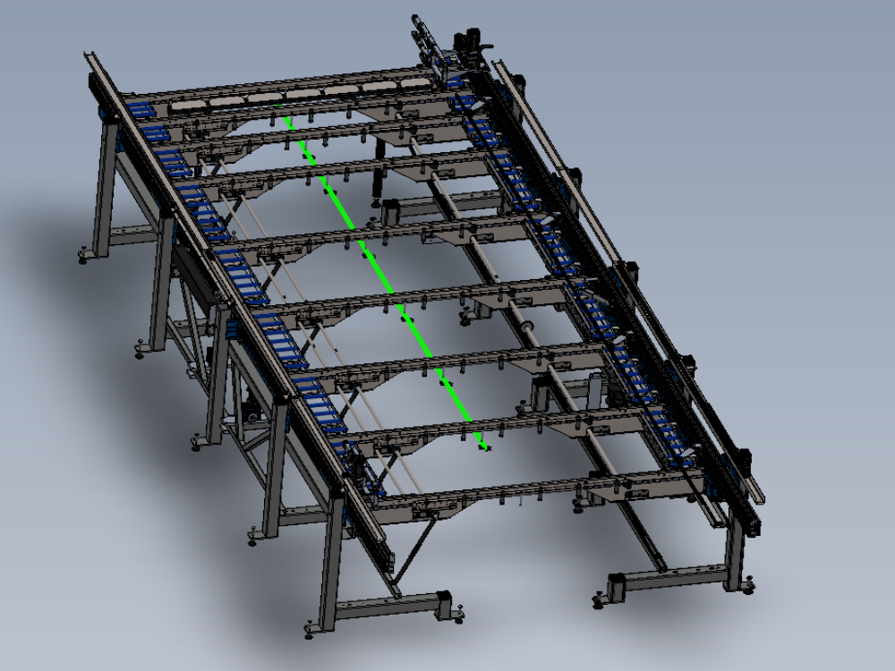
Étape 2 - Fit connection rail
Fit pre assembled connection rail

Étape 3 - Add energy chain mounting brackets
Fit energy chain mounting brackets to cylinder rails

Étape 4 - Connect energy chains from modules
Connect fitted energy chains from modules C and E to brackets
Étape 5 - Add Y connections
Break into feed lines on cylinder rails with 6mm y fittings

Étape 6 - Connect Feed pipes
Connect feed pipes from energy chain to supply Y fittings
Étape 7 - Add P0000551 Quick exhaust valves
Add 3 off per side P0000551 qev valves to feed pipes
Étape 8 - Connect cylinder rail 1 pipe loom
Connect cylinder rail 1 pipe loom to connection rail

Étape 9 - Connect cylinder rail 2 pipe loom
Connect cylinder rail 2 pipe loom to connection rail
Étape 10 - Connect cylinder rail 3 pipe loom
Connect cylinder rail 3 pipe loom to connection rail
Étape 11 - Connect cylinder rail 4 pipe loom
Connect cylinder rail 4 pipe loom to connection rail
Étape 12 - Connect cylinder rail 5 pipe loom
Connect cylinder rail 5 pipe loom to connection rail
Étape 13 - Connect cylinder rail 6 pipe loom
Connect cylinder rail 6 pipe loom to connection rail
Étape 14 - Connect cylinder rail 7 pipe loom
Connect cylinder rail 7 pipe loom to connection rail
Étape 15 - Connect cylinder rail 8 pipe loom
Connect cylinder rail 8 pipe loom to connection rail
Étape 16 - Connection test
Once all pneumatic connections have been made, an air test is required to identify any connection leaks
2349 Disconnect from module C multi head outfeed valve bank and connect to air supply. Check no audible leaks are present and all cylinders identified as 2349 fire and pistons extend. Check that pistons retract when air is removed
2339 Disconnect from module C multi head outfeed valve bank and connect to air supply. Check no audible leaks are present and all cylinders identified as 2339 fire and pistons extend. Check that pistons retract when air is removed
2329 Disconnect from module C multi head outfeed valve bank and connect to air supply. Check no audible leaks are present and all cylinders identified as 2339 fire and pistons extend. Check that pistons retract when air is removed
2319 Disconnect from module E Saw infeed valve bank and connect to air supply. Check no audible leaks are present and all cylinders identified as 2319 fire and pistons extend. Check that pistons retract when air is removed
2309 Disconnect from module E Saw infeed valve bank and connect to air supply. Check no audible leaks are present and all cylinders identified as 2309 fire and pistons extend. Check that pistons retract when air is removed
2299 Disconnect from module E Saw infeed valve bank and connect to air supply. Check no audible leaks are present and all cylinders identified as 2299 fire and pistons extend. Check that pistons retract when air is removed

Draft
 Français
 English
 Deutsch
 Español
 Italiano
 Português