Bench assembly details for roller fences

Difficulté
Moyen
Durée
1 heure(s)
Introduction
Tools Required
Standard hex key set
1 meter straight edge
Feeler gauges
Bearing dolly for B0000245 Needle Bearing
Parts Required
B0000245 Needle Bearing 12 D 16 D 10 Long (ENA) x 20
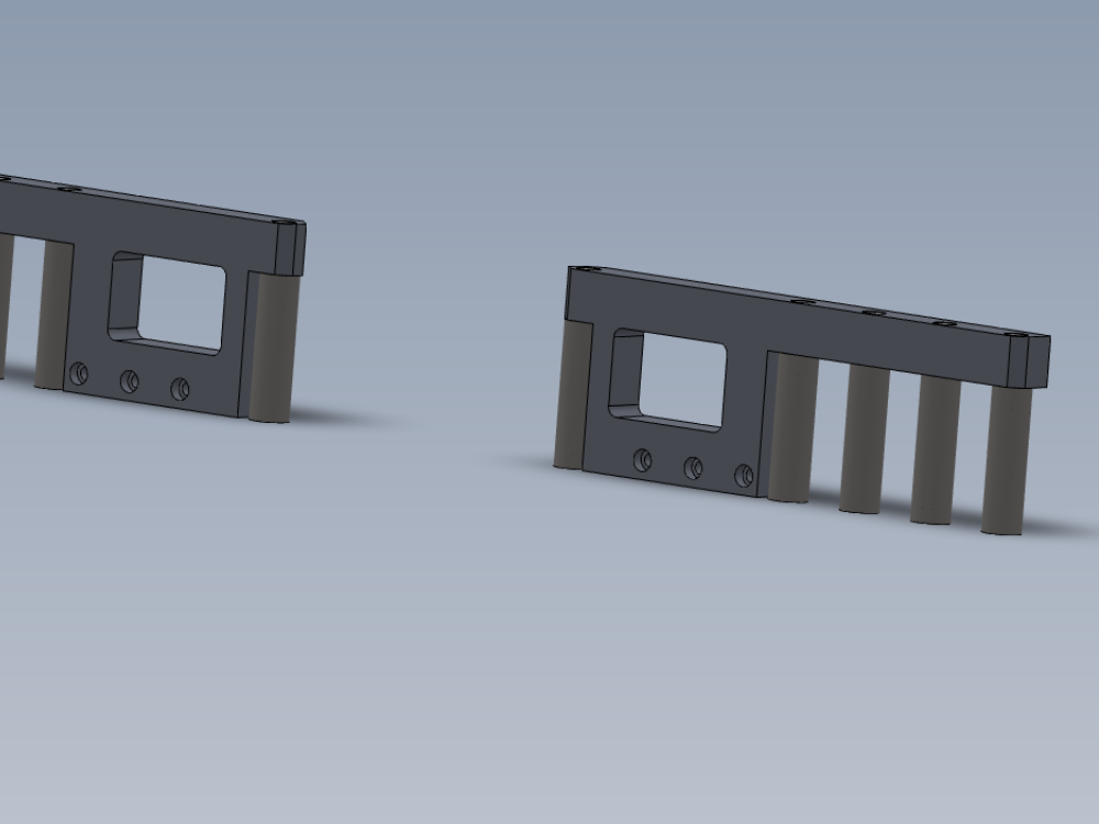
D0005183 Roller Backfence (D7443) x 1
D0005184 Guide Roller x 10
D0005186 Guide Pin Washer x 10
D0007443 Roller Backfence OH (D5183) x 1
H0005185 Shaft 12mm: 90.5 Saw Fence Roller Pin x 10
Étape 1 - Unless otherwise stated
All bolts to have Loctite 243 adhesive applied unless otherwise stated
All Threaded Pneumatic connections to have Loctite 570 applied
All bolts to be pen marked once adhesive applied and correct tension added

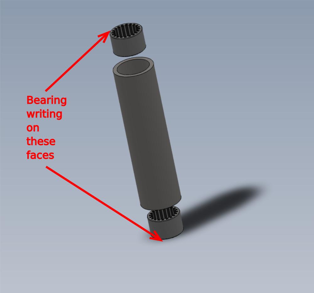
Étape 2 - Fit bearings to rollers
Assemble 10 off D0005184 Guide Roller
Each roller has 2 off B0000245 Needle Bearing fitted
Ensure bearings and rollers are thoroughly degreased before fitting
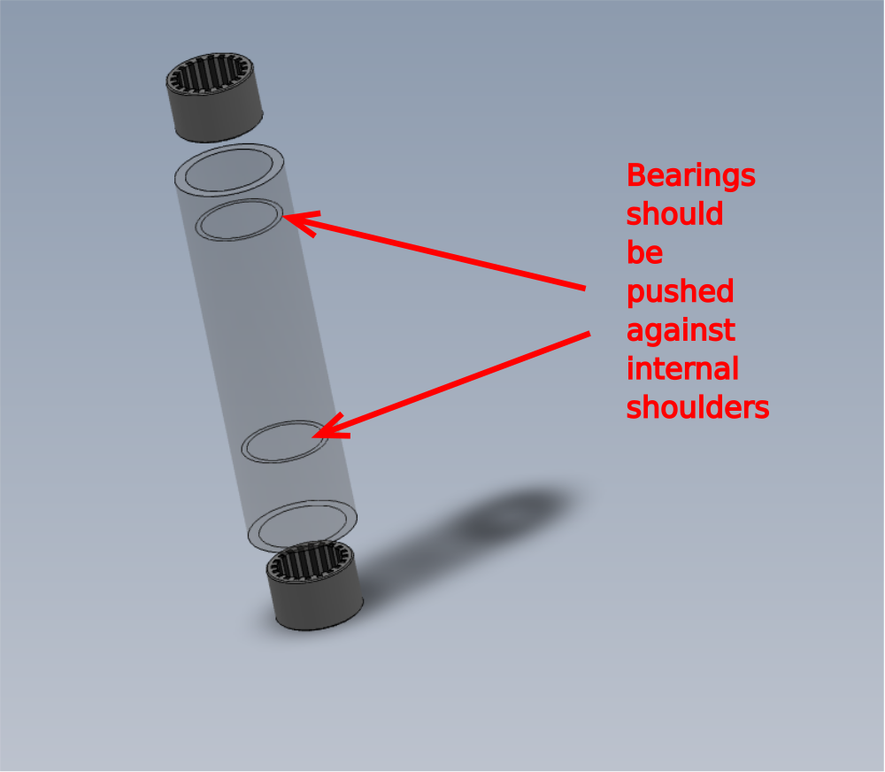
Ensure bearings are fitted correct orientation . Writing on edge of bearing should be face outwards
Use bearing dolly and push bearing down to should within roller body


Étape 3 - Grease rollers
Apply liberal grease to all bearings within rollers


Étape 4 - Fit guide pin washers
Fit 10 off D0005186 Guide Pin Washer to H0005185 Shaft 12mm: 90.5 Saw Fence Roller Pin
Hold shaft in vice and use M5 x 12 socket cap to secure washer to end of shaft . Finalise bolt with loctite 243
Repeat for all ten shafts/washers


Étape 5 - Fit Rollers
10 off
Fit pre assembled rollers to assembled shafts
clean excess grease from shafts once fitted


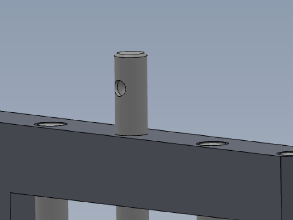
Étape 6 - Shaft orientation
Dimples in H0005185 Shaft are not used in this application.
When fitting shaft , position dimple 180 degrees opposing M6 fixing point in backfence

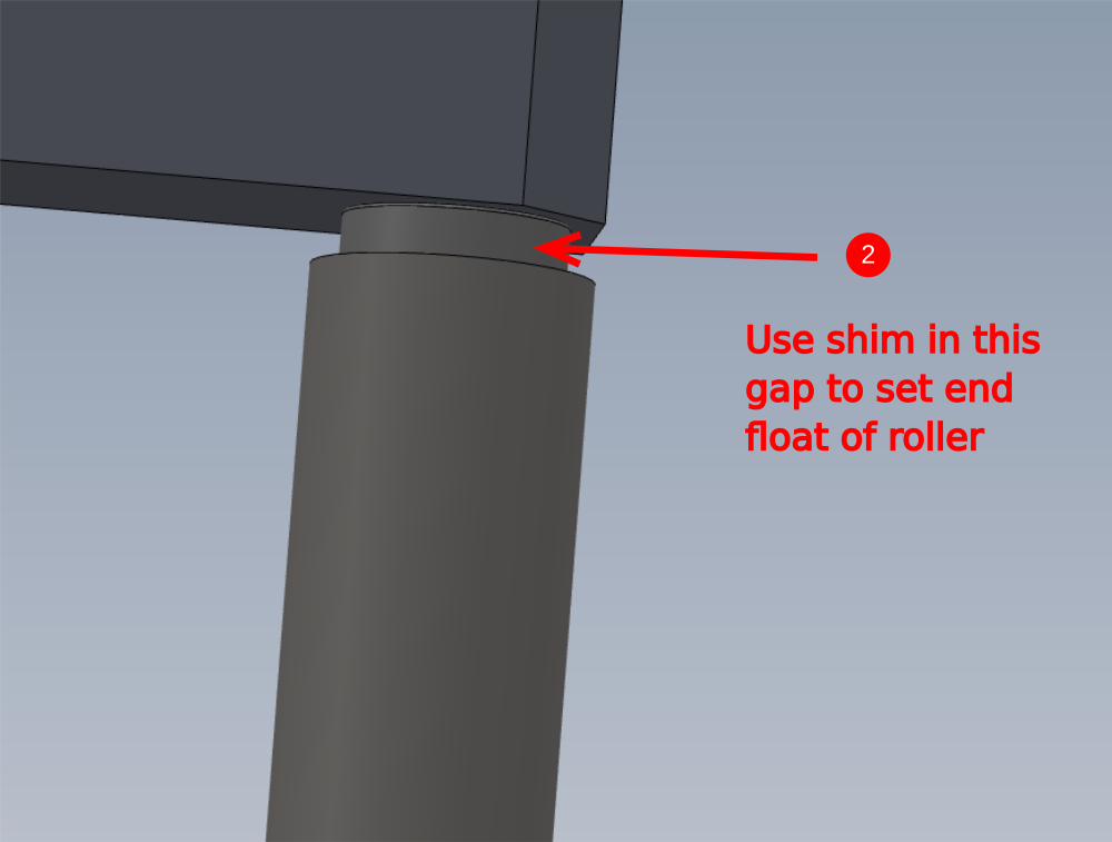
Étape 7 - Position rollers
1 insert shaft into bore following previous step information
2 Insert 0.125mm/0.005" shim between roller and backfence at indicated point
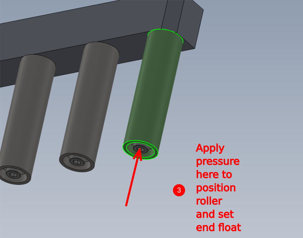
3 Apply very light hand pressure to area shown to position shaft correctly
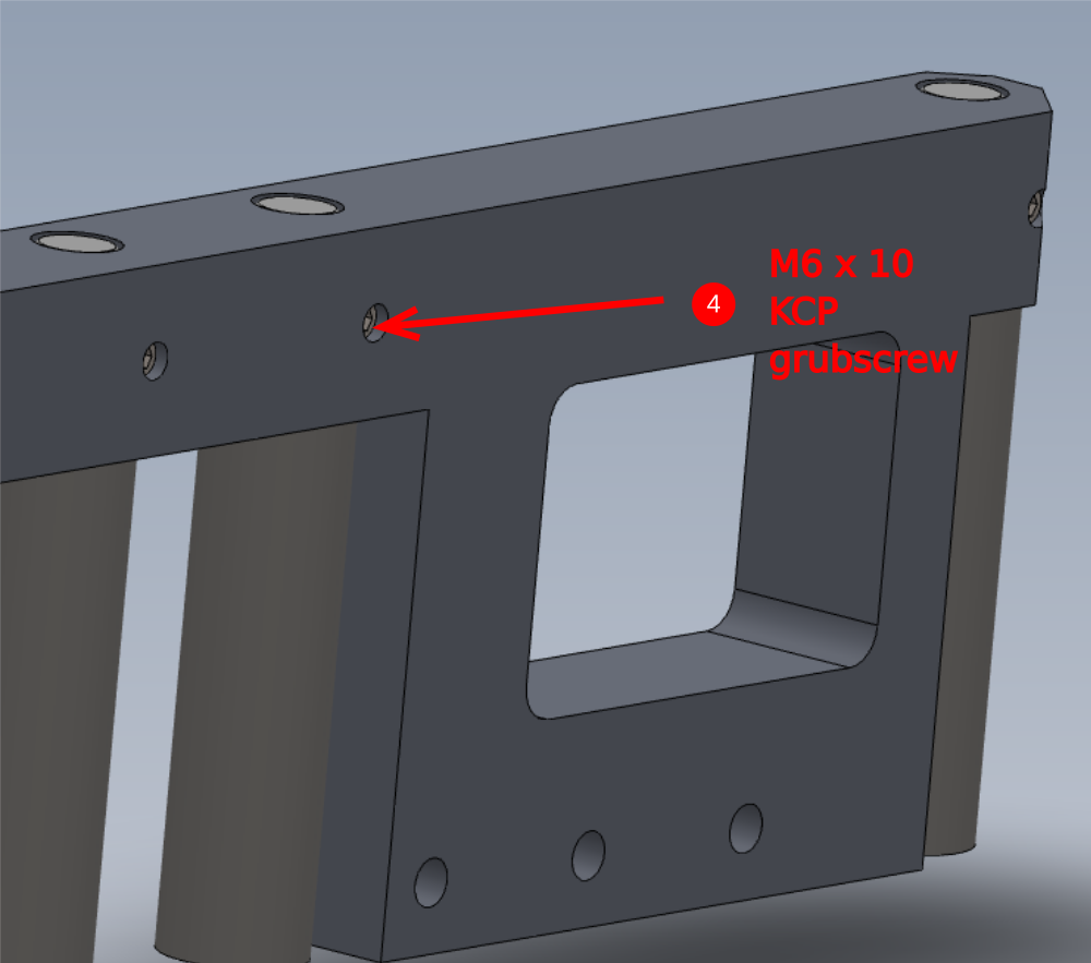
4 fit and finalise M6 x 10 kcp grubscrew to secure shaft
5 pull out shim from under roller
Repeat for all ten rollers

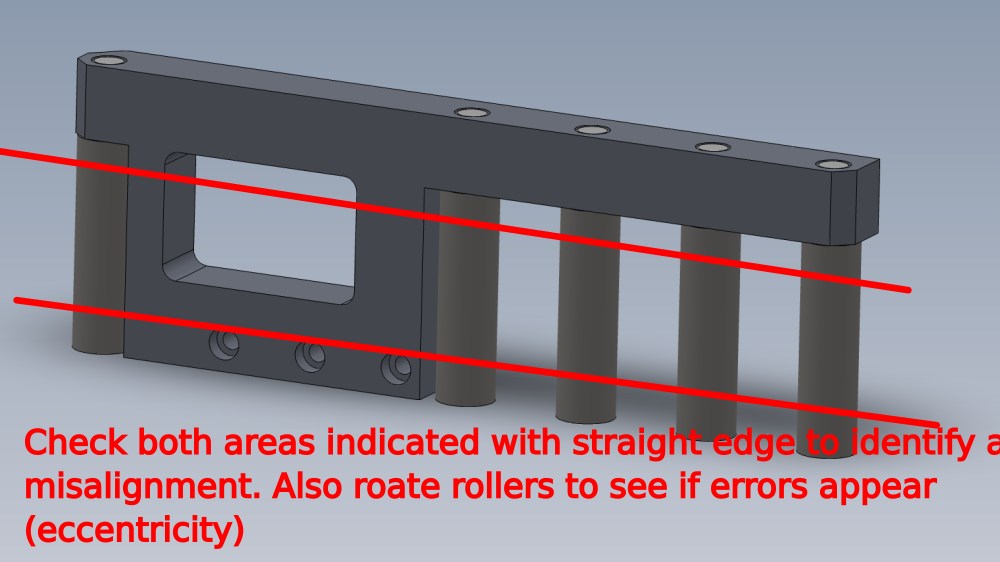
Étape 8 - Quality check
Use 1 meter straight edge to check alignment of rollers
Place straight edge against front face of rollers
Use feeler gauges to check
Mis alignment of rollers on the plain indicated
Rotate rollers individually to check for eccentric rotation.
Report any discrepancies above 0.002"/0.05mm to supervisor
All rollers should be free moving and consistent when rotated


Draft
 Français
 English
 Deutsch
 Español
 Italiano
 Português