Assembly details for conveyor frame
Sommaire
- 1 Introduction
- 2 Étape 1 - Unless otherwise stated
- 3 Étape 2 - Drill blower points on rollers
- 4 Étape 3 - Assemble mounts
- 5 Étape 4 - insert M4 plate nuts
- 6 Étape 5 - Assemble main frame
- 7 Étape 6 - Finalise all fasteners
- 8 Étape 7 - Fit Slave roller (non driven)
- 9 Étape 8 - Fit drive roller
- 10 Étape 9 - Attach adhesive tape
- 11 Étape 10 - Fit stainless top plates
- 12 Étape 11 -
- 13 Commentaires
Introduction
Tools Required
standard hex key set
Standard spanner set
Standard HSS drill set
Standard tap set
Utility knife
Parts Required
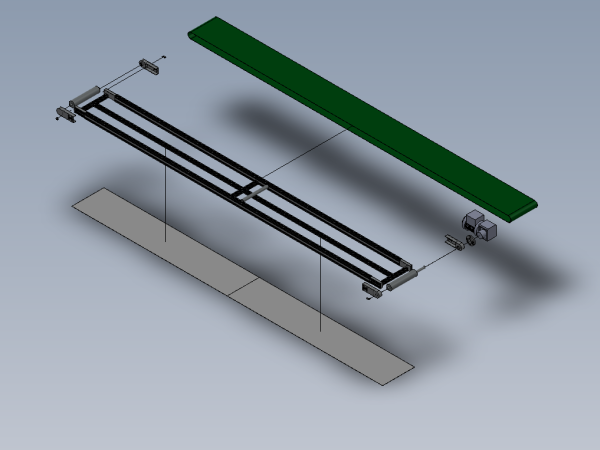
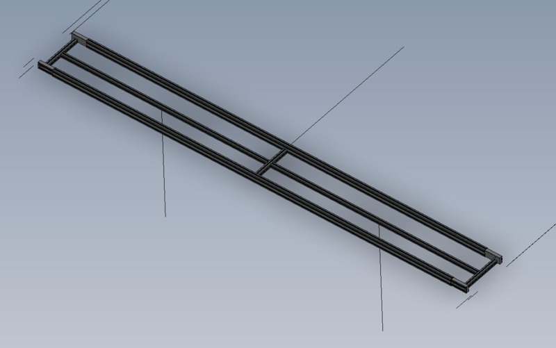
B0000441 Conveyor 3580mm x 300mm x 1
B0001013 Conveyor Motor SEW - WA 10 x 1
B0001177 Pair conveyor side cheeks and bearings slave x 2
M0000133 Conveyor Belt XL-AS 7350 x 300 B x 1
P0000200 Elbow Adaptor 6mm - M5 x 3
Étape 1 - Unless otherwise stated
Use Loctite 243 on all fasteners
Use Loctite 572 on all threaded pneumatic connection
Pen mark all fasteners to show finalised
Étape 2 - Drill blower points on rollers
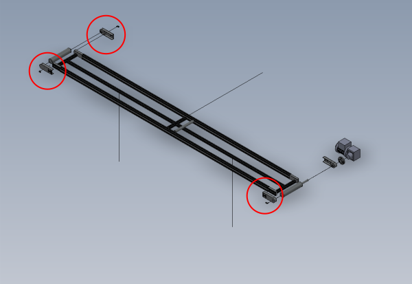
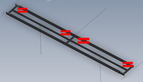
indicated 3 roller housings will require blower holes adding
Please include all drilling details for this procedure
Étape 3 - Assemble mounts
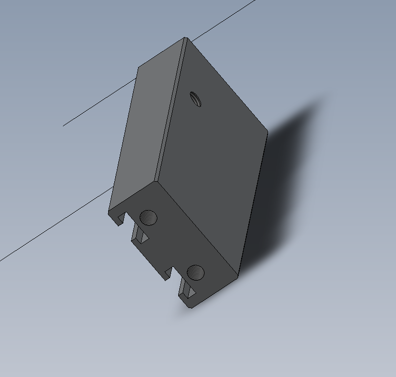
Assemble 4 off mounts
Each mount has 3 off maytec fittings
Ensure maytec fittings are orientated correctly
Étape 4 - insert M4 plate nuts
insert 8 off supplied m4 plate nuts into correct face of long frame sections
Étape 5 - Assemble main frame
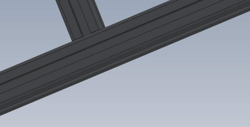
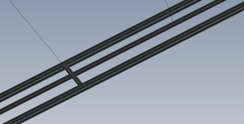
Assemble main maytec frame
Ensure all sections are set in a parallel position
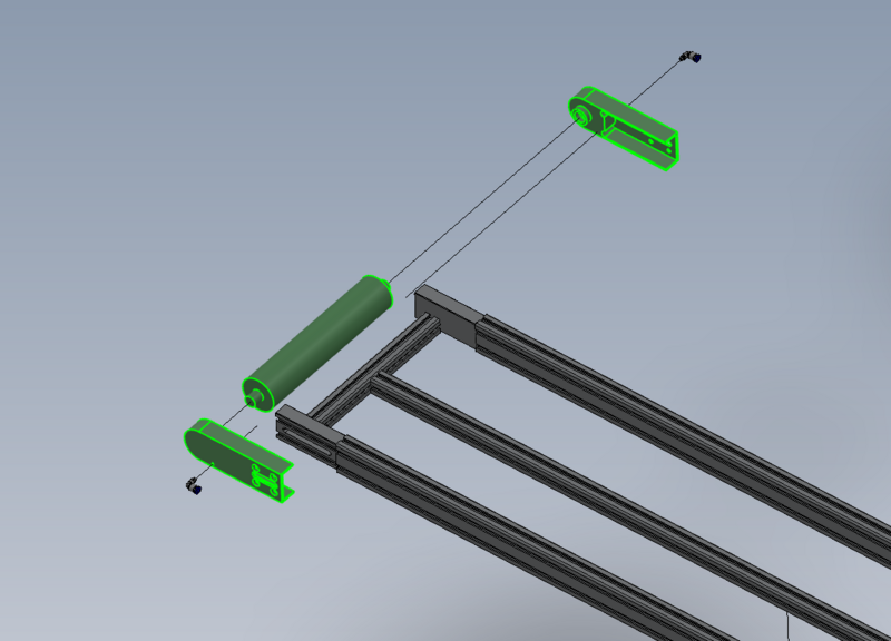
Étape 7 - Fit Slave roller (non driven)
Fit slave roller assembly as shown
Ensure blower points are orientated correctly to suit belt rotation direction
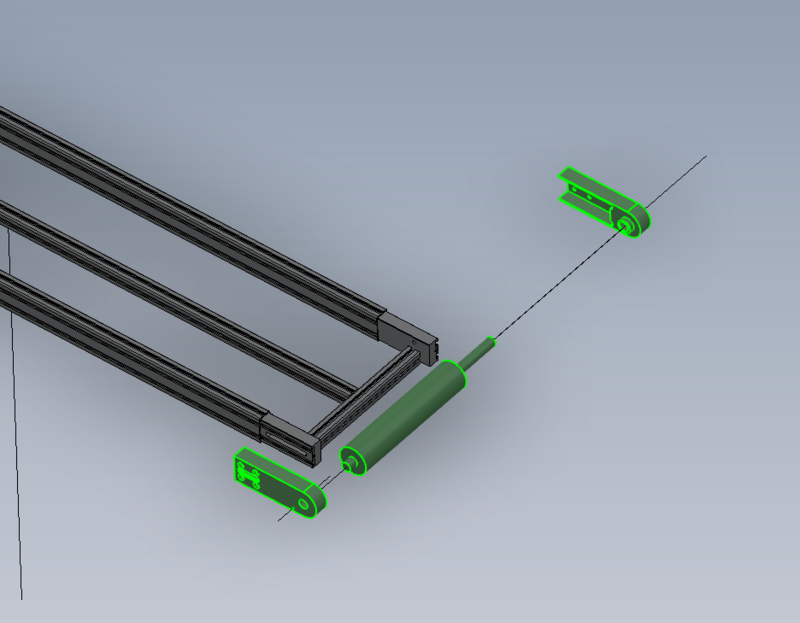
Étape 8 - Fit drive roller
Fit drive roller assembly as shown
Ensure blower point is orientated correctly to suit belt rotation direction
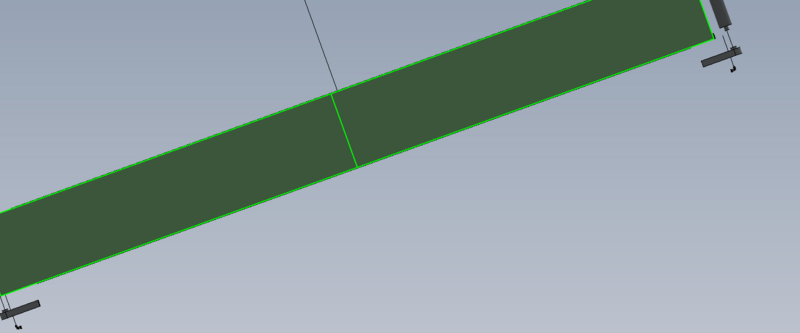
Étape 10 - Fit stainless top plates
Use stainless plates as a guide to align M4 plate nuts before removing adhesive tape backing
Once aligned , remove adhesive tape backing and secure stainless plates into position
Fit 8 off supplied m4 countersunk hex sockets to finalise stainless plate fitting
Étape 11 -
Draft


 Français
 English
 Deutsch
 Español
 Italiano
 Português