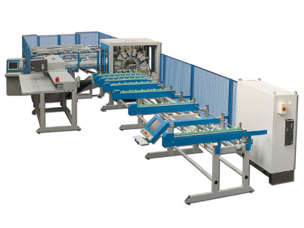
This tutorial will provide a step by step guide on how to upgrade a ZX style machine to have Beckhoff drives and control system.
Sommaire
- 1 Introduction
- 2 Étape 1 - Preparation (Base)
- 3 Étape 2 - First Fix Servo Cabinet
- 4 Étape 3 - Preperation (On-Site)
- 5 Étape 4 - Remove Components - MH (Electrical)
- 6 Étape 5 - Remove Components - Saw (Electrical)
- 7 Étape 6 - Remove Components - Saw Infeed (Electrical)
- 8 Étape 7 - Remove Components - Field Components
- 9 Étape 8 - Fit Parts - MH (Electrical)
- 10 Étape 9 - Fit Parts - Saw (Electrical)
- 11 Étape 10 - Fit Parts - Transfer (Electrical)
- 12 Étape 11 - Fit Servo Cabinet
- 13 Étape 12 - Wiring Cabinets
- 14 Étape 13 - Run Machine Cabling
- 15 Étape 14 - Upgrade Console - MH
- 16 Étape 15 - Upgrade Console - Saw
- 17 Étape 16 - Terminate Machine Wiring
- 18 Étape 17 - Tidying and Checks
- 19 Étape 18 - Machine Wiring Changing
- 20 Commentaires
Introduction
Étape 1 - Preparation (Base)
Check through all parts lists and make sure that the parts that have been requested are the parts that are in the box. The picked parts should include all the consumable products that are in the BoMs (bolts, tie wraps, wires etc).
Once parts have been checked, they need to be handed to production for pre-assembly.
Ensure all information and drawing packs are available in the service job and in the relevant technical information boards on Monday.com. Link to Monday board for drawing packs here:
Étape 2 - First Fix Servo Cabinet
Before the upgrade is despatched to site, the servo system needs to be assembled and pre-wired in its enclosure.
- Drill off Fan detail in right hand side of cabinet. A 114mm hole saw and arbor has been purchased for this.
- Drill and fit 4 adjustable feet in the bottom of the cabinet. 4 extra nuts will be in the kit. The height of the feet does not need to be set at this stage.
- Drill off all servo drives. For ZX3 machines, the rack will be as follows: AX8640-AX8118-AX8206-AX8206 and for a ZX4 the will be: AX8640-AX8118-AX8206-AX8206-AX8206 (the extra drive is for the V and W axes).
- Pre-wire the rack (inc STO links) and the cabinet fan with the cable provided in the kit. leave the spare coil of cable in the cabinet ready for running on-site.
- Plug in the 2x15m green etherCAT cables.
- The enclosure bottom plate is left off to allow the cable entry on site.
*for detailed wiring information, please use drawing packs from Monday.com board.*
Étape 3 - Preperation (On-Site)
Parts
The parts should arrive on site, packed as a kit. Check the parts for any obvious signs of damage and check through to make sure you have received what was expected.
Expectations
Before starting any works, check in with the customer and make sure that all parties are aware of the scope of the work being undertaken. It is good to set expectations at this point, to keep clarity between you and the customer.
Starting the Job
Check machine condition and get pictures before starting any work. It may be useful to run the machine to check any inherent issues before the upgrade begins. After works have been started, it will not be possible to come back to this stage.
Étape 4 - Remove Components - MH (Electrical)
It is important to note that although the components are being removed from the machine, they are not to be thrown away. Please keep all parts in good condition and find a place to store them until the end of the upgrade process.
Where wiring needs to be disconnected, try and keep crimped ends attached so that the wires can be reused later in the upgrade process.
Parts to be removed from MH cabinet:
- Main PC.
- Servo Drives.
- Breakout boards for Servo drives.
- Motion controller.
- Filters and resistors for Servo system.
- Smartdrive control box and associated cards.
- All network switches and modem devices.
Étape 5 - Remove Components - Saw (Electrical)
Parts to be removed from Saw Cabinet:
- Ace PC
- Nextmove ESB Controller
- Servo Drive
- Breakout board for Servo Drive
- Filter and Resistor for Servo Drive
- 12Vdc Power Supply
Étape 6 - Remove Components - Saw Infeed (Electrical)
Parts to be removed from Saw Infeed Cabinet:
- B&R PLC (or Omron)
- LEDs on cabinet door
Étape 7 - Remove Components - Field Components
Parts to be removed:
- Touchscreen from MH Console
- Keyboard and PS2 cable from MH Console
- Touchscreen from Saw Console
- VGA and any USB or PS2 cables from Saw Consoles
- Printer serial cable
- SX axis servo cablesfrom Saw cabinet through to SX axis motor
- X axis servo cables from MH rear plug join to X axis motor
- X axis servo cables from MH drop down panel to MH rear plug join
- G axis stepper cable from MH drop down panel to MH rear plug join
- Y, Z and R axis servo cables from MH drop down panel to servo motors
- X, Y, Z and R axis servo cables from MH Cabinet to MH drop down panel
- G axis stepper cable from MH cabinet to MH drop down panel
Étape 8 - Fit Parts - MH (Electrical)
Parts to be fitted in MH cabinet:
- Beckhoff IO Slices
- Beckhoff IPC
- Front End PC
- 24Vdc 10A Power Supply
- 3Pole 10A Breaker for Servo System
- 1Pole 3A Breaker for 24Vdc 10A Power Supply
- Din Mount Network Switch
*For any IO wiring that will not reach the IO slices, terminals are provided in the kit. The terminals can be used to extend the wiring.*
Étape 9 - Fit Parts - Saw (Electrical)
Parts to be fitted in Saw Cabinet:
- Beckhoff IO Slices
- Din Mount Network Switch
Étape 10 - Fit Parts - Transfer (Electrical)
Parts to be fitted in Saw Infeed Cabinet:
- Beckhoff IO Slices
Étape 11 - Fit Servo Cabinet
Position:
The servo cabinet will arrive pre-wired and have 4 feet fitted to the bottom. The cabinet needs to be placed at the rear of the MH outfeed, just after the first eject push cylinder. To get the cabinet inplace, the first fence panel will need to be removed. Eventually this fence panel will need to be cut to allow the cabinet door to open.
Fixing:
To fit the cabinet, first set the feet so that the top rear holes of the cabinet line up with the round bar frame of the MH outfeed. Once the holes line up, they can be drilled off and fixed.
Cables:
The cabinet will have a power cable and 2 network cables that need to be loomed out of the bottom panel of the cabinet. The power cable and network cable labelled MH, run into the MH, through the internal trunking, through the drop down panel (ensure cables are run and secured in such a fashion that the drop down panel can be open or closed without causing any clashes or breaks for the cables. The cables then run down the infeed table trunking and into the MH electrical cabinet.
The network cable labelled Saw, will eventually run through the front buffer beam of the transfer table, but at this stage it just need to be loomed up to the entrance of the buffer beam, ready for pulling through with some other cables later on.
Étape 12 - Wiring Cabinets
Now all wiring and devices have been fitted in the cabinets. Use the schematics provided to wire them up.
The schematics can be found on the Monday.com board linked at the start of this Dokit.
Étape 13 - Run Machine Cabling
Étape 14 - Upgrade Console - MH
Étape 15 - Upgrade Console - Saw
Étape 16 - Terminate Machine Wiring
Étape 17 - Tidying and Checks
Étape 18 - Machine Wiring Changing
Saw Angles
Saw Infeed Datum
Polarity Changes
Saw Start Button
On/Off Circuits
Draft


 Français
 English
 Deutsch
 Español
 Italiano
 Português